Article

Sand Removal Mechanism of a High-Speed Roller Bit with Helical Sealing

School of Mechatronic Engineering, Southwest Petroleum University, Chengdu 610500, China
*
Author to whom correspondence should be addressed.
Appl. Sci. 2019, 9(18), 3830; https://doi.org/10.3390/app9183830
Submission received: 18 July 2019 / Revised: 9 September 2019 / Accepted: 9 September 2019 / Published: 12 September 2019
(This article belongs to the Section Mechanical Engineering)

Abstract

:
A roller bit is a drilling tool widely used in oil and gas exploitation. The roller bit is applied to cutting the rock stratum, and its working life and rotational speed are important factors affecting the drilling efficiency. Moreover, a bearing sealing affects the working life and rotational speed of a bit. This paper proposes a helical sealing structure that addresses the problems of severe sealing wear and a short working life. This structure has been used in many engineering fields but was first applied to the roller bit. This paper investigates the sand removal mechanism of helical sealing through simulation and experiment. Additionally, helical sealing parameters were optimized. The optimum structural parameters of helical sealing in a high-speed roller bit were obtained. It was shown that the helical sealing structure can be applied to a roller bit with good effects of sealing and sand removal.

1. Introduction

The roller bit is the tool most widely used in petroleum and geological drilling. Additionally, the roller bit has the functions of impacting, crushing, and cutting the rock stratum and can adapt to soft, medium, and hard strata. The development of long-life high-speed cone bits has become an important technical issue, which urgently needs to be addressed in petroleum drilling engineering. Improving the bit drilling speed and working life are effective ways of reducing the drilling cost. However, the sealing affects the bit drilling speed and working life and is also the weakest part of the bit. Field data have shown that the failure rate of roller bits due to early bearing damage is as high as 80%, and bearings seriously worn by early sealing failure account for 30% of all failed bearings [1,2,3,4,5,6,7,8]. The sealing has become a technical bottleneck that seriously affects the drilling efficiency and cost. There is thus an urgent need for a solution to this problem in petroleum engineering.
The entry of a slurry abrasive medium is the most critical factor affecting the sealing life of a high-speed roller bit [9,10,11]. All existing sealings are passive [12,13,14,15,16,17,18,19,20,21,22,23,24,25,26] and suffer serious aging and wear, limiting improvements in the bit speed and working life. In addition, poor working conditions (i.e., a high temperature, high abrasive medium, high load, and narrow sealing chamber) aggravate the sealing failure, leading to great difficulties and challenges in research [27,28]. The working life of a sealing can therefore be improved and the fundamental sealing problem can be solved by designing a sealing structure having the function of active sand removal.
Figure 1 shows that helical sealing is noncontact and hydrodynamic. As the roller bit rotates at high speed, the helical sealing structure has the characteristics of helical pumping and sand removal that prevent abrasive slurry from entering and wearing the bearing. Some mud can enter when the bit is stationary but can be removed as the bit rotates. The helical sealing structure can realize active sand removal without using the traditional O-ring and thus overcomes the aging and wearing problems caused by passive sealing and improves the bit speed and operation. A historical change in roller bit sealing can thus be realized.

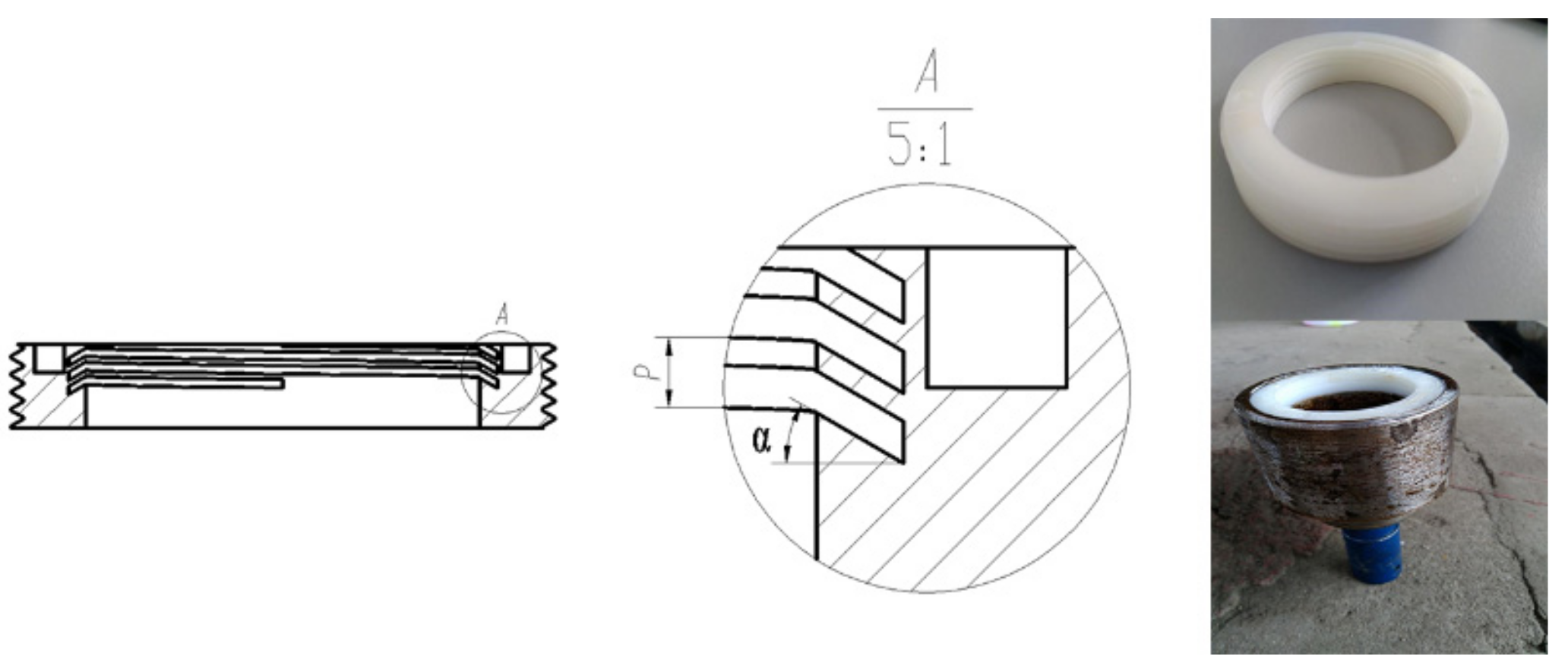
2. Spiral Seal Sealing Theory

Figure 1 shows that there are three types of flows in a helical sealing according to the flow balance theory of Crease [29]. (1) Liquid mud outside the bearing sealing chamber can leak inside the sealing chamber along the helical groove; this leakage is denoted Q L 1 . (2) Liquid mud outside the bearing sealing chamber can leak along the annular gap between the helical sealing ring and bearing; this leakage is denoted Q L 2 . (3) Pumping pressure generated by the helical sealing ring has an associated flow rate Q P . The pumping flow is the flow of the Kuta in the tank, and the flow rate is as follows:
Q P = v cos 2 α b g d i 2 .
From the geometry of the spiral structure:
b g i = π r D tan α .
Then the final pumping flow formula is:
Q p = π v D d r sin α cos α 2 ,
where r = b g b g + b l , v is the seal surface rotation speed, α is the spiral angle, bg is the axial groove width, d is the groove depth, i is the number of threads, bL is the axial tooth width, D is the sealing diameter.
Due to the certain viscosity of the mud liquid, it will form a dynamic balance in the sealed cavity under the pumping action of the spiral seal, and the mud particles are continuously discharged outside the cavity to ensure that the mud particles do not enter the sealed cavity.
According to the principle of helical sealing, the direction of pumping flow should oppose the direction of leakage flow. The factors affecting the pumping flow direction of helical sealing are the screw type (i.e., the helical sealing of the screw shaft or the helical sealing of the screw sleeve [30]), the direction of the screw thread (i.e., left or right), and the direction of bearing rotation (i.e., clockwise or counterclockwise). The helical sealing in the present study was installed in the inner hole of the roller, which belongs to the helical sealing of the screw sleeve. To prevent slurry debris from entering the sealing chamber, the direction of pumping flow should be outward of the sealing chamber. A right-handed thread and counterclockwise rotation of the shaft were thus selected [31,32].

3. Methods

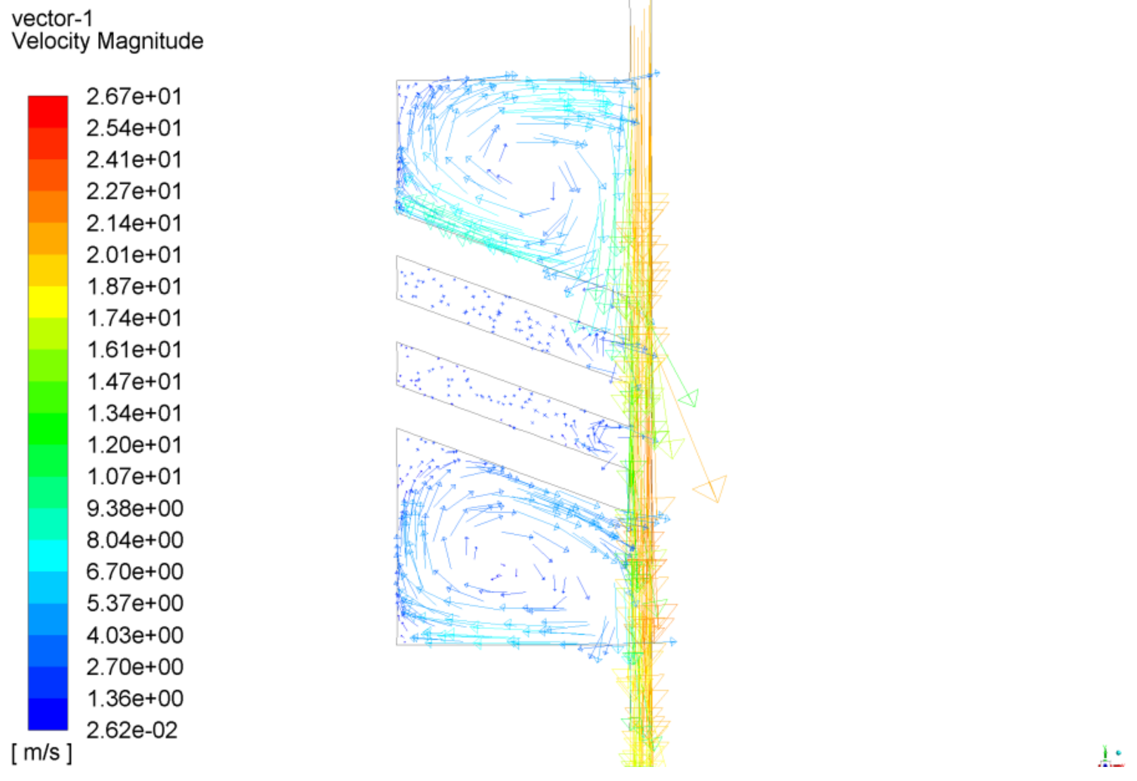
3.1. Numerical Simulation

This study uses FLUENT 15.0 (ANSYS, Inc. Canonsburg, PA, USA) to simulate the flow field distribution of helical sealing. In the actual working conditions at the bottom of the well, the temperature of all fluid boundaries is the same, and the movement of the fluid is not affected by the temperature. Therefore, the assumption in the simulation solution process is that the thermal coupling was not considered. After discovering and confirming the bottom hole gas overflow, it is necessary to carry out relevant operations to prevent the bottom hole gas from overflowing before drilling can continue. Therefore, when the roller bit is working, there is almost no gas in the bottom mud, the gas overflow from the bottom hole was not considered. Due to the certain gap between the spiral seal ring and the bearing, the spiral seal ring does not collide with the bearing to cause deformation when the roller bit is working. Since the material of the spiral sealing is metal, the deformation caused by the temperature is small and negligible. Therefore, the deformation of the metal spiral seal was not considered. The simulation model in this paper was generated by modeling software. In this process, the actual roller bit model was solved by Boolean operation, and the cavity model of the roller bit, that is, the flow channel model in Figure 2 was obtained. The mesh generation is an important step in flow field simulation. The mesh types are mainly divided into structured and unstructured grids. The structured grids are homogenous and are difficult to construct for the complex shape. The spatial distribution of unstructured grids is random with no specific structural characteristics and adaptability and can adapt well to a complex shape. An unstructured mesh was generated in this paper because the helical structure is complex and small in size. The generated mesh had a cell number of 219,122, and the number of nodes was 54,262.
Both the inlet and outlet were set as pressure boundary conditions. A shallow well with a depth of 940 m was studied in this paper. The mud density was 1200 kg/m3 and the mud viscosity was 0.2 Pa·S. Additionally, the pressure at the mud inlet was 11 MPa. Because the theoretical pressure difference between the inside and outside of the sealing chamber is 0.3–0.7 MPa, the actual pressure difference was greater than the theoretical pressure difference. Moreover, the safety factor was 1.5, and the pressure difference between the inside and outside was set at 1.05 MPa. The outlet pressure was 12.05 MPa [33]. The wall boundary condition was used for simulation, and a non-slip wall was set. The inner wall was set as a rotating wall, which comprises an inner roller hole and helical sealing ring. The rotational speeds of the roller and sealing ring were the same. Other walls were set as static walls with zero velocity [34], and the rotational speed of the bit was 200 r/min.
It was assumed using the discrete phase model in FLUENT that the second phase (i.e., the particle phase) was thin, such that the interaction between debris pieces and the effect of the particle volume fraction on the continuous phase need not be considered. This assumption means that the volume fraction of the discrete phase must be low, generally less than 12 percent.
The drilling bit parameters were an 8 1/2-inch drilling bit; i.e., d = 216 mm. The mudflow rate was V = 30L/s and the drilling rate was 6 m/h. The volume of rock debris per second VY was
V Y = π d 2 2 × h = 3.14 × 0.108 2 × 6 3600 = 0.00006104 m 3 / s = 0.06104 L / s ,
The volume fraction of rock debris per second was
V Y V = 0.06104 30 = 0.002047 = 0.2047 % 10 % .
The calculation results show that the volume fraction of rock debris is far less than 10%–12%. The discrete-phase simulation was therefore applied to the movement of rock debris in the flow field. The rock debris was set at the entrance surface, and the jet source and inert debris were selected. The incident velocity of the cuttings was set to 0.1 m/s, the diameter of the particle phase particles was 0.001 mm, so that its motion state moved with the movement of the liquid. Additionally, the entrance and exit boundary conditions were set as the escape boundary conditions. The wall boundary conditions were set as reflective, where the debris rebounded and the momentum changed. Moreover, the variation was determined by the rebound coefficient.

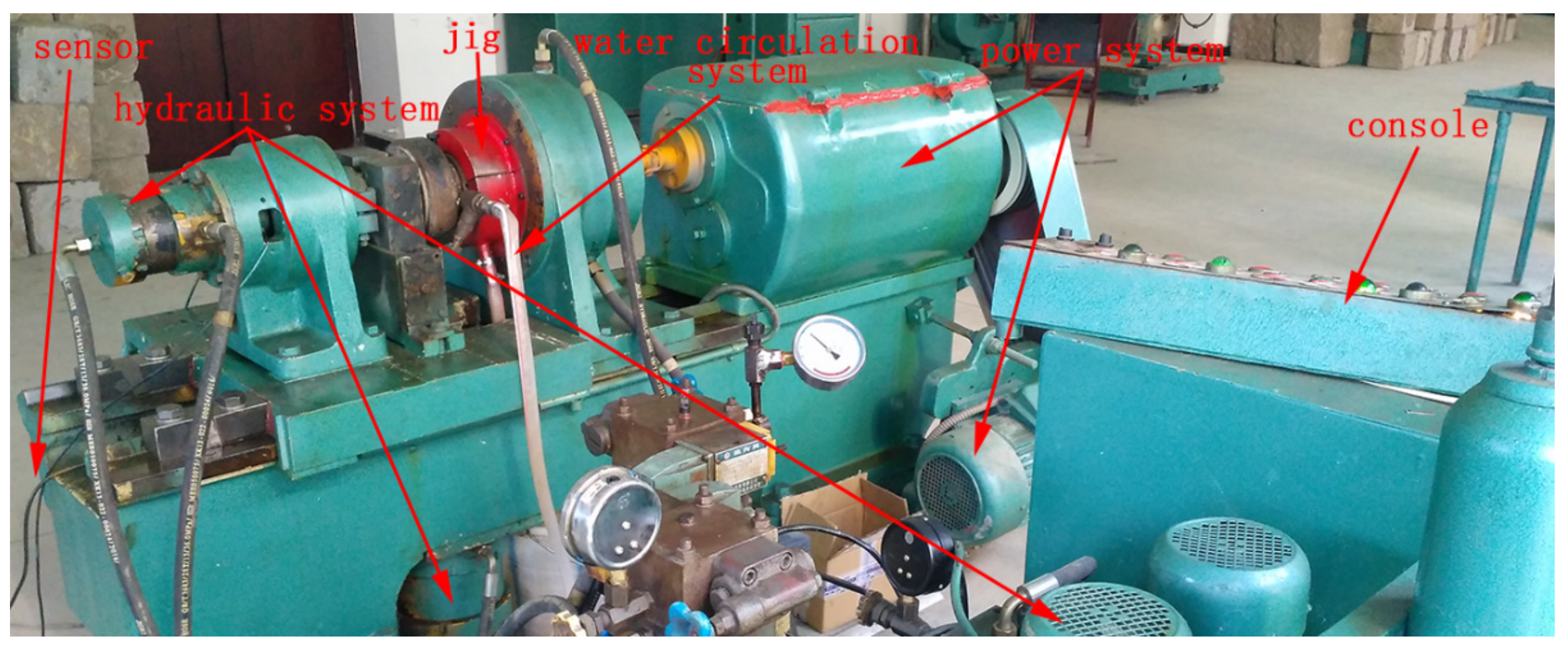
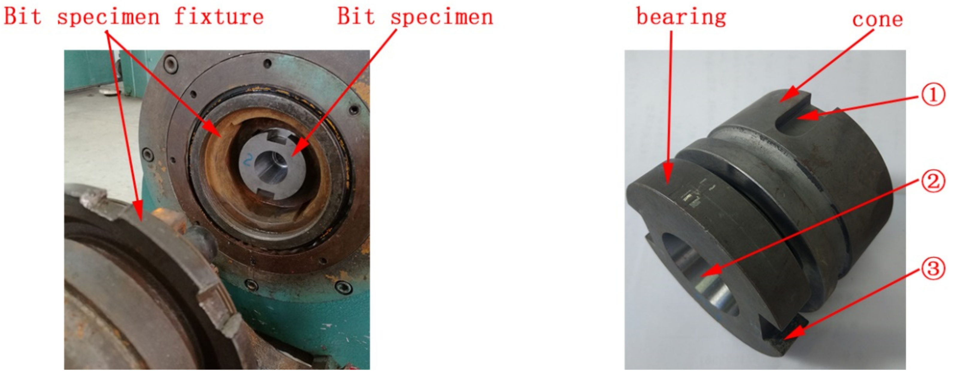
3.2. Experimental Device

The first test was a uniaxial test without pressure. This study independently developed a horizontal helical sealing test device (as shown in Figure 3 and Figure 4). The helical sealing ring installed in the roller (19) was thin (only 0.8–1.2 mm in thickness) and not strong enough to meet the working conditions; it was thus easily damaged and needed to be replaced frequently. The helical sealing ring and helical shaft sleeve were therefore designed as a whole (26) (as shown in Figure 5). On the one hand, the roller (19) does not need to be frequently replaced, which reduces costs and improves efficiency. On the other hand, the strength of the helical seal is enhanced. The inner part of the helical sleeve (26) is a helical sealing ring (for helical sand removal) and the outer part is a thread (for assembly with the inner hole of the roller). The helical sleeve (26) was printed in three dimensions and was installed on the roller and rotates with it.
Under the driving action of the roller (19), the helical sleeve (26) rotates at high speed. The rotated helical sleeve (26) generates an axial driving force for the liquid injected into the gap. There is thus a pumping effect, and the liquid in the gap is removed from the roller (19) to achieve the sealing.
The second test was a pressure medium uniaxial test. As for the actual conditions of the well bottom, as the drilling bit operates, the volume of the bearing volume changes owing to vibration of the bearing system, and the thermal expansion and vapor pressure of grease generated by friction heat increase the pressure difference. The pressure difference between the inside and outside of the sealing cavity is about 0.3–0.7 MPa. The liquid container 3 was replaced by a pump having this pressure difference, and the liquid was pumped to the A and B lines, and the remaining steps were the same as in the first experiment. This experiment was based on the first test device to increase the pressurized pump to simulate the actual working conditions.
The third test was a uniaxial bit loading test. A special high-speed bearing test was conducted to simulate actual working conditions (as shown in Figure 6). This test can exert axial and radial loads on a bit for testing the sealing performance. As for the device, the position of the drilling bit is shown in Figure 7. Moreover, the drilling bit comprises a roller and bearing. The groove at roller position (1) was applied to the axial and circular locations of the roller. The grooves at bearing positions (2) and (3) were respectively used for the axial and circular locations of the roller. The wear-resistant alloys were machined on the bearing side with a radial load to increase the wear resistance, which is consistent with the actual drilling process.

3.3. Experimental Procedure

In the first test, the uniaxial test without pressure mainly verifies the feasibility of helical sealing and the effects of different helical structure parameters on the sand removal performance. The pumping weight measurement method was used to weigh the liquid entering the device and the liquid removed from the device. The flow direction is shown in Figure 4. The roller (19) was connected with the motor (17) and the bearing (25) was stationary. As the motor (17) was stationary, the roller (19) did not rotate and the helical sealing (26) did not have a pumping function. The liquid was injected into the liquid container (3) with a mass of 5000 g, and the valve (4) was opened. Additionally, the liquid entered the working place of the helical sealing through two symmetrical holes along the axes of entrances A and B. The pumping function of the helical sealing (26) ring with high speed allowed liquid to flow into the active removal device. The liquid was removed through outlet (E) and along outlets (C) and (D). The liquid in the container (14) was weighed and the weight difference between the liquid entering and the liquid collected was calculated. The difference was the leakage of the helical sealing, and the sand removal performance of the helical sealing can be evaluated. As the motor (17) operates the roller (19) rotated with high speed, the roller (19) can drive the rotation of the helical sleeve (26) to realize the helical sealing (where helical sealing plays the role of pumping and removing sand). On the premise of the same volume of liquid being injected into the liquid container (3), the above test process without pumping action was repeated, and the difference in the pumping weight was recorded. The performance of helical sealing was evaluated by comparing the weight difference between the same volume of liquid entering and removed with the motor not working (i.e., the helical sealing ring has no pumping effect) and the motor working (i.e., the helical sealing ring can drive and remove sand). When the motor was not working, the weight difference was great because the screw cannot pump the sand. When the motor was working, the weight difference was small because of the pumping sand removal of helical sealing. The weight difference was thus inversely proportional to the performance of helical sand removal. The above results are used to evaluate the performance of helical sealing sand removal. As the roller rotates, the optimum rotational speed and helical structure parameters were obtained by measuring the pumping weight for different rotational speeds and helical structure parameters. By comparing the sealing weights, the pumping and sand removal effects of the helical sealing can be evaluated. A large weight difference suggests that the helical sealing does not have a sand removal effect whereas a small weight difference suggests that helical sealing has a sand removal effect. Meanwhile, this method can be used to test the sand removal performance of helical sealing with different helical structure parameters. The weight difference is inversely proportional to the sand removal performance of the helical sealing. The optimum rotational speed and helical structure parameters can thus be obtained.
In the second test, the uniaxial test of the pressurized medium investigated whether there was liquid infiltration in the sealing chamber. The sealing performance was good if there was no liquid infiltration in the sealing chamber; otherwise, the sealing did not meet the requirements. This was the main criterion for evaluating the sealing performance of the helical sealing ring.
In the third test, the axial load was 0.3 t while the radial load was 1 t (which was the maximum allowable output load in the high-speed bearing test). The test environment was filled with a water medium at a pressure of 0.3 MPa, and the device intermittently worked for 30 h (where the intermittent operation was to simulate the tripping and stopping of drilling). The working life of a conventional roller bit is 30 h. After the test, the water in the sealing cavity of the drilling bit can be observed. If the sealing fails, the sealing cavity will flood and the grease will dilute and escape the sealing cavity. If the sealing performance is good, the sealing cavity will not flood, and the grease will be applied to the bearing.

4. Results

4.1. Feasibility Study

4.1.1. Numerical Simulation

The velocity field in Figure 8 shows that the fluid entering the sealing chamber can directly flow through the gap, and the velocity direction is from the upper part to the lower part of the flow channel. Other fluid flows in a clockwise direction in the helical flow channel. As the fluid flows to the gap, the tangential component of the velocity is from top to bottom, which indicates that the spiral pump works. Meanwhile, the overall flow direction is from the upper end to the lower end of the flow channel, which is consistent with the direction of helical sand removal.
The pressure field presented in Figure 9 shows that the pressure gradually decreases from the upper end to the lower end of the flow channel, and the high pressure concentrates in the upper part of the flow channel. The pressure is lowest (9.94 MPa) at the lower end and highest (10.8 MPa) at the upper end. Additionally, the inlet pressure at the upper end is 11 MPa. It is suggested that the screw has the functions of pumping sand and reducing the upper pressure. Moreover, mud debris is subjected to a downward force and removed from the upper end to the lower end. The pressure curve shows that the trend of pressure distribution is a decrease from top to bottom, which is convenient for sand removal. Sections labeled a–e in Figure 10 at the turning point of the screw pitch are studied. The curve of the pressure change rate can be obtained from the pressure curve; i.e., the value obtained by the first-order differential of the pressure distribution reflects the rate of change in pressure at a certain axial position. The pressure increases with the axial distance when the pressure change rate is positive and decreases with increasing axial distance when the pressure change rate is negative. A lower change rate of pressure thus results in a faster pressure drop and better sand removal. The pressure change rates at axial sections b, c, and d rapidly decrease to a minimum within a relatively small axial distance and more rapidly than those at other axial sections. It is suggested that each stage of the screw promotes a pressure drop and the removal of sand. Helical structure parameters (i.e., the screw pitch, screw angle, and sealing gap) have an important effect on the pumping capacity and sand removal performance. Further research is needed.
Figure 11 shows the detention of rock debris. The black line outlines the three-dimensional model of the flow channel, the blue line represents the trajectory of particle movement in the sealing gap, and the green line represents the trajectory of particle movement in the whirlpool. Most of the debris is removed directly through the sealing gap. Little of the debris is in a swirling flow state in the channel. The maximum retention time (0.0406 s) is short, indicating the rapid removal of sand.

4.1.2. Experimental Research

Figure 12 and Figure 13 shows that the bearing interior is dry before the test as the roller bit is fitted with a threadless sleeve (without helical sealing). After the test, a large area of liquid infiltrates the sleeve and sealing chamber. As the roller is fitted with the helical sealing, the sealing chamber is dry before the test. After the test, there is some liquid at the end of the spiral ring and the initial ring (because the mud injection end is located at the hole of the sealing sleeve end). There is no liquid infiltration in the sealing chamber, and the bearing interior is dry. It is thus demonstrated that the removal of sand by the helical sealing is feasible.

4.1.3. Simulation of a Uniaxial Test Machine

Figure 14 shows the dismantled roller at the end of the test. After disassembly, the bearing and roller are covered with grease. The grease is applied to the bearing and roller without water.
In summary, theoretical, simulation, and experimental results show that the sand removal of helical sealing is feasible.

4.2. Optimization of Structural Parameters of the Helical Sealing

The above results show that the helical structure parameters affect sand removal performance. On the premise that other structural parameters are unchanged, one structural parameter is changed to study its effect on the sand removal performance, which provides guidance and a basis for structural design. Because the sand removal direction is determined by the helical direction, the variations of helical structure parameters do not change the helical direction, and the sand removal direction (the velocity direction) is unchanged. The velocity is thus no longer analyzed in the numerical analysis in this section.

4.2.1. Numerical Simulation

According to previous research, the detention time of rock debris and the sand removal performance are respectively proportional and inversely proportional to the pressure change rate. The above are thus selected as criteria by which to judge the performance of sand removal.
1. Effect of the pitch
Considering the limited height of the sealing chamber, the pitch of the helical sealing ring is inversely proportional to the ring number. However, the ring number cannot be great. Otherwise, the small pitch can affect the efficiency of sand removal and the strength and working life of the sealing. Additionally, the ring number cannot be small, as the pumping will be ineffective. Three rings are thus selected in this paper. Pitches of 1.6 mm, 2.0 mm, and 2.4 mm are selected with the ring number and other structural parameters unchanged.
As shown in the numerical simulation results of Table 1, the pressure change rates at helical structures b, c, and d are extracted and their average values obtained. With an increasing screw pitch, the pressure change rate gradually decreases, the pressure drop rate increases, the detention time of rock debris decreases, and the sand removal performance worsens. For a pitch of 2.4 mm, the pressure change rate is lowest, the detention time of rock debris is shortest, and the sand removal performance is best.
2. Effect of the sealing gap
With other structural parameters unchanged, sealing gaps of 0.5 mm, 0.8 mm, and 1.1 mm are selected to study the gap effect on the sand removal performance. As shown in the numerical simulation results of Table 1, the pressure change rate gradually increases, the pressure drop rate decreases, the duration of movement of rock debris increases, and the sand removal performance decreases with an increasing sealing gap. The sand removal performance is best for a sealing gap of 0.5 mm.
3. Effect of the inclination of the helical surface
With other structural parameters unchanged, the sand removal performance is observed for inclinations of the helical surface of 23°, 27°, and 30°. The numerical simulation results presented in Table 1 show that the pressure first increases and then decreases with increasing inclination. The pressure change rate is lowest for an angle of 23°. With increasing inclination, the movement time of rock debris first decreases and then increases. At inclinations of 23° and 27°, the differences in the pressure change rate and particle retention time can be neglected. However, experimental data show that the sand removal performance is best for an inclination of 23°, which is selected in this paper.
The average pressure change rate and the detention time of rock debris change most with a variation in the sealing gap, among the three structural parameters, which indicates that the gap has the greatest effect on the sand removal performance.

4.2.2. Experimental Research

The pumping weight measurement method refers to the measurement of the weight of liquid entering the device and the weight of liquid removed after operation of the device. The draining liquid amount and the sand removal performance are proportional to the weight difference. Table 1 shows that the weight difference is smallest and the sand removal performance is best for a pitch of 2 mm, a gap of 0.5 mm, and inclination of 23°. The simulation and experimental results of the gap and inclination are consistent, but the simulation and experimental results of the screw pitch are slightly different owing to inevitable systematic error and measurement error.
The comprehensive experimental and simulation results show that the sand removal performance increases with a decreasing gap, an increasing screw pitch, and a decreasing inclination of the helical surface.

5. Discussion

First, the rotation direction and the sealing mechanism of helical sealing are determined with sealing theory. According to the literature on helical sealing and the optimized helical structure parameters with better pumping performance, the helical sealing structure is preliminarily determined by combining the size of the roller bit with the specific working conditions. This structure is then selected as the original model with which to lay the foundation for subsequent simulation.
This paper conducts simulations and experiments to verify the feasibility of helical sealing and then to optimize the structural parameters. For the feasibility analyses, a three-dimensional model of a flow channel is established on the basis of the original model. Moreover, a discrete phase model is established with the boundary conditions set up. Results show that the velocity direction from the top to bottom of the sealing end can achieve good sand removal performance. The pressure field is distributed from high to low. Additionally, it is found that the variation rate of pressure can abruptly change at each variation level of the screw, and the pressure can rapidly decrease, promoting the removal of sand. Meanwhile, the helical structure parameters play an important role in the performance of sand removal. The remaining amount of rock debris decreases and the sand removal performance increases with a decreasing migration time of rock debris. According to the simulation study, the sealing mechanism is revealed to verify the feasibility of helical sealing, and the main factors affecting the sand removal performance are investigated, while criteria for judging the sand removal performance (i.e., a downward direction of movement, low-pressure change rate, and short migration time of rock debris) are obtained. Through experimental study, the sealing effects with and without helical sealing are compared. Because variations in the pressure field and velocity field cannot be experimentally studied, the sealing performance is evaluated by observing the water leakage of the sealing chamber, as shown in Figure 12 and Figure 13. Additionally, the difference in weight of the roller at rest and rotation is measured (16.25 g versus 7.5 g); it is found that the roller at rest has no sand removal effect and the roller with high speed has a good sand removal effect. It is feasible to apply the helical sealing to the high-speed roller bit. The feasibility of helical sealing is verified according to the simulation and experiment.
To obtain the helical sealing structure with good sand removal performance, the influence rule of main helical sealing parameters on the sand removal performance is studied through feasibility analyses. Additionally, optimum parameters are determined and provide a theoretical basis for subsequent practical application. Experiments and simulation reveal that the sand removal performance is inversely proportional to the gap (where on account of the bit processing coordination, the gap cannot be small but should be as small as possible in the feasible range), proportional to the screw pitch, and inversely proportional to the inclination of the helical surface. The simulation and experimental results of the sealing gap and helical inclination are consistent. The sand removal performance is best for a sealing gap of 0.5 mm and inclination of 23°. There is a slight difference between the simulation and experimental results of the screw pitch, which may be due to errors in the measurement, equipment, and operation. According to the theoretical analyses, the pumping performance is proportional to the screw pitch. Simulation results show that the difference between the pressure and residence time is small for pitches of 2 mm and 2.4 mm. A pitch of 2.4 mm is selected in this paper.
The above experimental research does not apply the drilling pressure to the bit, which is conducted on sealing equipment independently developed by us. After the successful experiment, a simulation of the uniaxial testing machine is carried out, with the aim of simulating the bottom hole load and mud condition and the helical sealing performance at work and at rest. Results show that the helical sealing structure can effectively prevent the external medium from entering the bearing system (as shown in Figure 14).
In this study, a new type of “spiral seal” structure is proposed, which has a screw pumping action under high-speed rotation through a spiral seal ring to discharge the debris particles out of the sealed cavity, thereby prolonging the service life of the roller bit. The proposed new structure breaks the current idea of passive sealing and converts passive sealing into active sealing, which marks the birth of a new sealing concept, which can bring huge economic and social benefits.

Author Contributions

Conceptualization, Y.Z.; methodology, Y.Z.; software, B.T.; validation, B.T. and Y.H.; investigation, Y.Z.; resources, Y.Z.; writing—original draft preparation, Y.H. and B.T.; writing—review and editing, Y.Z. and B.T.; visualization, Y.H.; supervision, Y.Z.

Funding

This research was funded by the National Natural Science Foundation of China, grant number 51604238.

Conflicts of Interest

The authors declare no conflict of interest. The funders had no role in the design of the study.

References

  1. Xiong, J.Y.; Qian, S.H.; Yan, R.J. New progress in efficient rock breaking in drilling. Nat. Gas Ind. 2004, 24, 27–29. [Google Scholar]
  2. Li, T.Y. Comparative analysis of drilling characteristics between diamond bit and roller bit. Drill. Prod. Technol. 1999, 22, 58–60. [Google Scholar]
  3. Shi, X.C.; Tao, Z.W.; Meng, Y.F. Research progress on the mechanism of tooth breaking by cone bits. Geol. Sci. Technol. Inf. 2014, 33, 225–230. [Google Scholar]
  4. Wang, Z.Y.; Peng, Q.M.; Su, M.R. Failure Analysis of Roller Bit Bearing System. J. Southwest. Pet. Inst. 1987, 3, 72–86. [Google Scholar]
  5. Flak, R.; Packer, S.; Steel, R.; Russel, M.; Taylor, B. Friction Stirring and Its Application to Drill Bits, Oil Field and Mining Tools, and Components in Other Industrial Applications. U.S. Patent Application 11/136,609, 23 May 2005. [Google Scholar]
  6. Hall, D.R.; Cross, D.G. Polycrystalline Diamond Bearing System for a Roller Cone Rock Bit. U.S. Patent 4,738,322, 19 April 1988. [Google Scholar]
  7. Xiao, X.; Chen, B.; Sun, C.M.; Liu, Y.X.; Xu, Y.S. Optimization Analysis of Bimetal Seal Structure for High Speed Cone Bit Bearings. J. China Pet. Mach. 2014, 42, 30–33. [Google Scholar]
  8. Zahradnik, A.F.; Nguyen, D.Q.; Mccormick, R.D.; Koltermann, T.J.; Veasey, M.J. Seal Replace Ring for Roller Cone Bits. Seal. Technol. 2008, 2007, 15. [Google Scholar]
  9. Jiang, R.C. Preliminary analysis of factors affecting the life of roller cone bits. Min. Process. Equip. 1981, 1, 10–16. [Google Scholar]
  10. Wang, S.L.; Jin, B. Prospective study on improving the life and reliability of roller cone bits. Foreign Oilfield Eng. 2003, 10, 27–29. [Google Scholar]
  11. Zhou, Y.; Huang, Z.Q.; An, X.B. Failure Analysis and Improvement of Bimetal Seal of High Speed Roller Bit Bearing. Oil Field Equip. 2011, 40, 50–53. [Google Scholar]
  12. Deng, M.K. Finite Element Simulation Analysis of Single Metal Seal Ring of Roller Bit. China Pet. Chem. Stand. Qual. 2013, 20, 124–125. [Google Scholar]
  13. Wu, S.X. O-ring and its mould. Oil Field Equip. 1985, 6, 51–64. [Google Scholar]
  14. González-Ciordia, B.; Fernández, B.; Artola, G.; Muro, M.; Sanz, A.; de Lacalle, L.N.L. Failure-Analysis Based Redesign of Furnace Conveyor System Components: A Case Study. Metals 2019, 98, 816. [Google Scholar] [CrossRef]
  15. Zhang, F.Y.; Liu, H.; Zhang, L.J. Research on the theory of hydraulic reciprocating sealing, technology and application. Lubr. Eng. 2007, 32, 198–201. [Google Scholar]
  16. Li, Z.C.; Yang, X.Q. Nonlinear Finite Element Analysis of Bearing Sealing Ring Deformation. Bear 2004, 11, 20–23. [Google Scholar]
  17. Wang, W.; Zhang, S. Nonlinear Finite Element Analysis of Rubber O-sealing Ring. Lubr. Eng. 2005, 4, 64–70. [Google Scholar]
  18. Zuo, Z.; Liao, R. Finite Element Analysis of Rubber Sealing Ring for Model 12150 Diesel Engine. Chin. Intern. Combust. Engine Eng. 1996, 2, 11–18. [Google Scholar]
  19. Denton, R.; Keshavan, M.K.; Peterson, S.W. O-Ring Seal for Rock Bit Bearings. U.S. Patent 5,456,327, 10 October 1995. [Google Scholar]
  20. Chen, F.; Chen, J.Q.; Liu, P.C. Study on Wear Resistance of WC-Co Coating on the Surface of Metal Ring of Roller Bit. Surf. Technol. 2009, 38, 1–2. [Google Scholar]
  21. Chen, F.; Chen, J.Q.; Yang, Y.G. Research progress on surface strengthening technology of metal end face of roller cone bit. New Technol. New Process 2009, 2009, 98–102. [Google Scholar]
  22. Wu, K.; Chen, X. Optimized Design of the Floating Bushing for the Sliding Bearing of Roller Bit. China Pet. Mach. 2013, 2, 57–64. [Google Scholar]
  23. Sun, J.; Chi, K.W.; Feng, M.L. Performance Analysis of Floating Face Seal Structure. Oil Field Equip. 2006, 35, 14–18. [Google Scholar]
  24. Zhang, B.S.; Chen, J.Q.; Liu, Z.Y. Improvement of single metal floating seal structure of roller cone bit SEMS2. China Pet. Mach. 2010, 8, 5–7. [Google Scholar]
  25. Zhang, B.S.; Chen, J.Q. Research on single metal floating sealing technology. Lubr. Eng. 2008, 3, 99–103. [Google Scholar]
  26. Li, B.; Liu, J.; Lu, D.W.; Chen, H.Y. Study on single metal sealing structure optimization of cone bit. Lubr. Eng. 2019, 44, 98–102. [Google Scholar]
  27. Wang, D.; Zhang, W.; Zhang, X.; Zhao, G.; Zuo, R.; Ni, J.; Yang, G.; Jia, J.; Yang, K.; Zhu, Y.; et al. Reaming Drilling Techniques of Hard Crystalline Rock. In The China Continental Scientific Drilling Project; Springer: Berlin/Heidelberg, Germany, 2015; pp. 211–232. [Google Scholar]
  28. Han, Z.Y.; Wen, L.R.; Zhang, J.L.; Li, Z.D. Judging the condition of the drill bit by using the comprehensive index method of the drill bit capacity. West China Explor. Eng. 1996, 2, 4–5. [Google Scholar]
  29. Crease, A.B. Windbackseals-a simple theory and design method and the main Pratical limitations. In Proceedings of the Seventh International Conference on Fluid Sealing, Nottingham, UK, 1975. [Google Scholar]
  30. Zhou, Z.A.; Ou, Y.X. Spiral sealing and sealing ability and its improvement. Chem. Equip. Technol. 1991, 5, 1–8. [Google Scholar]
  31. Chen, J.Q.; Luo, W. Structure Conception and Parameter Determination of Fluid Dynamic Pressure Seal of Roller Bit. Oil Field Equip. 1995, 24, 5–8. [Google Scholar]
  32. Ren, C.H.; Wei, J.T.; Li, Y.C.; Xu, Y.H. Sealing ability and parameter optimization of spiral seal. J. Northeast. Univ. (Nat. Sci. ). 2016, 37, 1755–1758. [Google Scholar]
  33. Zhou, Y.; Huang, Z.Q.; Li, Q.; Peng, S.J. Finite Element Analysis of Bimetal Seal of High Speed Cone Bit Bearing. Sci. Technol. Inf. 2011, 3, 423–424. [Google Scholar]
  34. Wu, G.Z.; Song, T.T.; Zhang, Y. FLUENT-Basic Entry and Case Proficiency, 1rd ed.; Electronic Industry Press: Beijing, China, 2012; Volume 3, pp. 280–312. [Google Scholar]
Figure 1. Helical seal structure.1. Cone; 2. steel ball; 3. bearing; 4. spiral seal.
Applsci 09 03830 g001
Figure 2. Boundary conditions.
Applsci 09 03830 g002
Figure 3. The appearance of the testing device. 1. Liquid container; 2. valve; 3. liquid container; 4. valve; 5. liquid line; 6. valve; 7. liquid line; 8. machine base; 9. bolt; 10. liquid tank; 11. bottom plate; 12. valve; 13. pipeline; 14. collection container; 15. bolt; 16. support frame; 17. electromagnetic speed regulating motor; 18. coupling; 19. roller; 20. end cap bolt; 21. bearing end cap; 22. cover; 23. bolt; 24. fixed pin.
Applsci 09 03830 g003
Figure 4. A sectional view of the testing device. 5. Liquid line; 6. valve; 7. liquid line; 11. bottom plate; 12. valve; 14. collection container; 15. bolt; 16. support frame; 17. electromagnetic speed regulating motor; 18. coupling; 19. cone; 20. end cap bolt; 21. bearing end cap; 25. bearing; 26. helical sleeve; 28. rolling bearing; 29. liquid outlet; 30. liquid inlet.
Applsci 09 03830 g004
Figure 5. Helical shaft sleeve.
Applsci 09 03830 g005
Figure 6. High-speed bearing testing machine.
Applsci 09 03830 g006
Figure 7. Drilling bit and fixture.
Applsci 09 03830 g007
Figure 8. Velocity field.
Applsci 09 03830 g008
Figure 9. Pressure field and pressure curve.
Applsci 09 03830 g009
Figure 10. Curve of the pressure change rate.
Applsci 09 03830 g010
Figure 11. The retention time of debris particles.
Applsci 09 03830 g011
Figure 12. Bearing before the test.
Applsci 09 03830 g012
Figure 13. Bearing after the test.
Applsci 09 03830 g013
Figure 14. Drilling bit after the test.
Applsci 09 03830 g014
Table 1. Optimization results of structural parameters.
Numerical Simulation ResultsTest Results
Structural ParametersThe Averaged Pressure Change Rate (Mpa/mm)Maximum Retention Time of Debris Particles (s)Optimization ResultsWeight Difference (g)Test Results
Pitch (mm)1.6−0.2010.05462.47.52
2.0−0.225330.04986.25
2.4−0.265670.04488.75
Sealing gap (mm)0.5−0.225330.02090.56.250.5
0.8−0.065670.068813.75
1.10.0030.082715
Inclination of helical surface (°)23−0.251330.0345236.2523
27−0.216330.032826.25
30−0.237670.056312.5

