Article

Model Tests of Soil Reinforcement Inside the Bucket Foundation with Vacuum Electroosmosis Method

1
State Key Laboratory of Hydraulic Engineering Simulation and Safety, Tianjin University, Tianjin 300072, China
2
Key Laboratory of Coast Civil Structure Safety (Tianjin University), Ministry of Education, Tianjin 300072, China
3
School of Civil Engineering, Tianjin University, Tianjin 300072, China
*
Author to whom correspondence should be addressed.
Appl. Sci. 2019, 9(18), 3778; https://doi.org/10.3390/app9183778
Submission received: 12 July 2019 / Revised: 22 August 2019 / Accepted: 23 August 2019 / Published: 9 September 2019

Abstract

:
Offshore wind turbine foundations are commonly subjected to large horizontal, vertical, and bending moment loads. Marine soils have high moisture content, high compressibility, high sensitivity, and low strength, resulting in insufficient foundation bearing capacity. In order to improve the bearing capacity of wind turbine foundations and reduce foundation settlement, an internal vacuum preloading method combined with electroosmosis reinforcement is used to reinforce the soil within bucket foundations. The pore water pressure, vertical settlement, pumping quality of the soil during the reinforcement process, soil moisture content before and after the reinforcement, and undrained shear strength were analyzed. Horizontal and vertical bearing capacity model tests were carried out on the reinforced and nonreinforced soil inside the bucket foundation. Results show that vacuum preloading combined with electroosmosis reinforcement reduces soil moisture content inside the bucket foundation by approximately 20%, and the undrained shear strength of the internal soil increases by approximately 20 times. Soil reinforcement has high spatial uniformity. Results of the bucket foundation bearing capacity model show that when the soil inside the bucket foundation is strengthened, horizontal bearing capacity increased by 2.9 times and vertical bearing capacity increased by 2.1 times. Vacuum preloading combined with electroosmosis reinforcement can effectively improve the shear strength of soft soil and enhance the bearing capacity and stability of bucket foundations.

1. Introduction

Offshore wind farms have been widely developed in recent years due to abundant offshore wind, lack of occupied land, and lack of pollution. Common types of offshore wind power generator foundations include single pile foundations, gravity foundations, jacket foundations, and floating foundations [1,2]; however, bucket foundations have been widely examined and employed in recent years due to their simple construction, low cost, and recyclability [3,4,5,6,7,8]. In 2018, the world’s largest single-capacity 8.8 MW wind turbine was successfully installed in the Aberdeen offshore wind farm in Scotland, and its foundation consists of four bucket foundations with a diameter of 9.5 m and height of 15 m [9].
The composite bucket foundation (CBF) is a new type of bucket foundation proposed by Tianjin University and Daoda Company, which adds bulkheads to the bucket and the transition section above the bucket foundation. The foundation can be prefabricated on land and transported and installed using a one-step installation vessel, which significantly reduces cost [10,11,12]. In November 2018, two wind turbines with a CBF foundation were installed in the Sanxia Dafeng Sea in Jiangsu, China. The prefabrication, transportation and installing processes are shown in Figure 1.
The seabed is commonly composed of silt, silty clay, and other marine soft soils with high water content, high compressibility, and low permeability, which commonly results in insufficient foundation bearing capacity and excessive settlement after foundation installation. In addition, during the installation of the bucket foundation, hydraulic fracturing of the soil in the bucket is caused by the large seepage force, which reduces the bearing capacity of the top cover of the bucket foundation [13]. Furthermore, cracks may form in the bucket wall, and the soil and foundation may separate during leveling of the bucket foundation [14,15,16]. Fracturing will destabilize and reduce the bearing capacity of the bucket foundation. Consequently, the soil inside the bucket foundation needs to be reinforced to improve the bearing capacity of the foundation. Soil failures during the installation of a bucket foundation are shown in Figure 2.
Ding et al. [17] applied a vacuum preloading method combined with electroosmosis reinforcement to the internal soil of the bucket foundation. The effectiveness of soil reinforcement was confirmed through a series of reinforcement model tests [18,19,20]. The vacuum-electroosmosis method for bucket foundation can be studied using existing vacuum preloading and electroosmosis methods. Vacuum preloading is performed by forming a vacuum under a sealing membrane covering the ground, and the pressure difference across the membrane causes the soil layer to consolidate, which increases the soil effective stress by reducing the pore water pressure without changing the total stress. The vacuum preloading method was first proposed by the Swedish civil engineer Kjellman in 1952 and has been widely used in soft soil foundation treatment [21,22,23,24,25,26,27,28,29]. Electroosmotic method is accomplished by applying a direct current at both ends of a soil deposit. The free water and weakly absorbed water in the soil move toward the cathode together with the cations, thereby draining and consolidating the soil. In 1939, Cassagrande in Germany used the electro-osmotic soil treatment method for the first time in an excavation of railway subgrade [30,31]. Electroosmosis improves the permeability coefficient of the soil and reduces the amount of weakly absorbed water regardless of grain assize [32]. In recent years, electroosmotic strengthening of soil has been widely studied [33,34,35,36]. This study employed a series of model tests to quantitatively analyze foundation settlement, pore water pressure inside the soil, soil moisture content before and after reinforcement, and undrained shear strength of the soil. The influence of electrode embedding, energization mode, and voltage level on reinforcement was studied. The effect of soil reinforcement on bucket foundation bearing capacity was studied using a series of model tests in clay.

2. Model Tests

2.1. Soil Preparation and Parameters
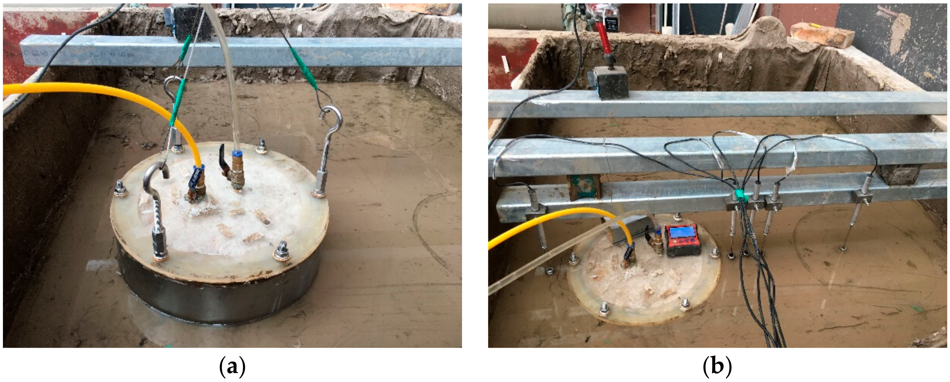
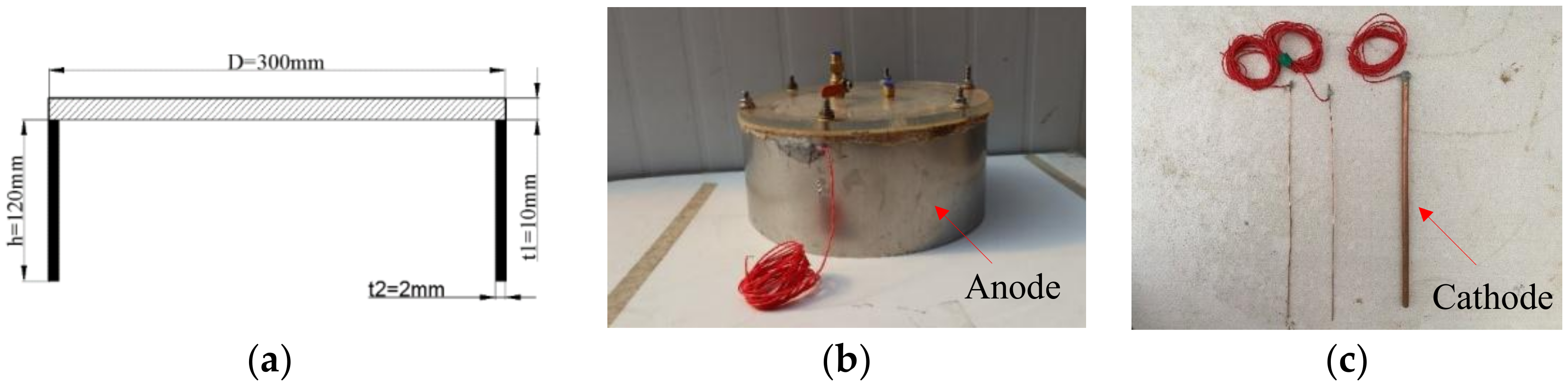
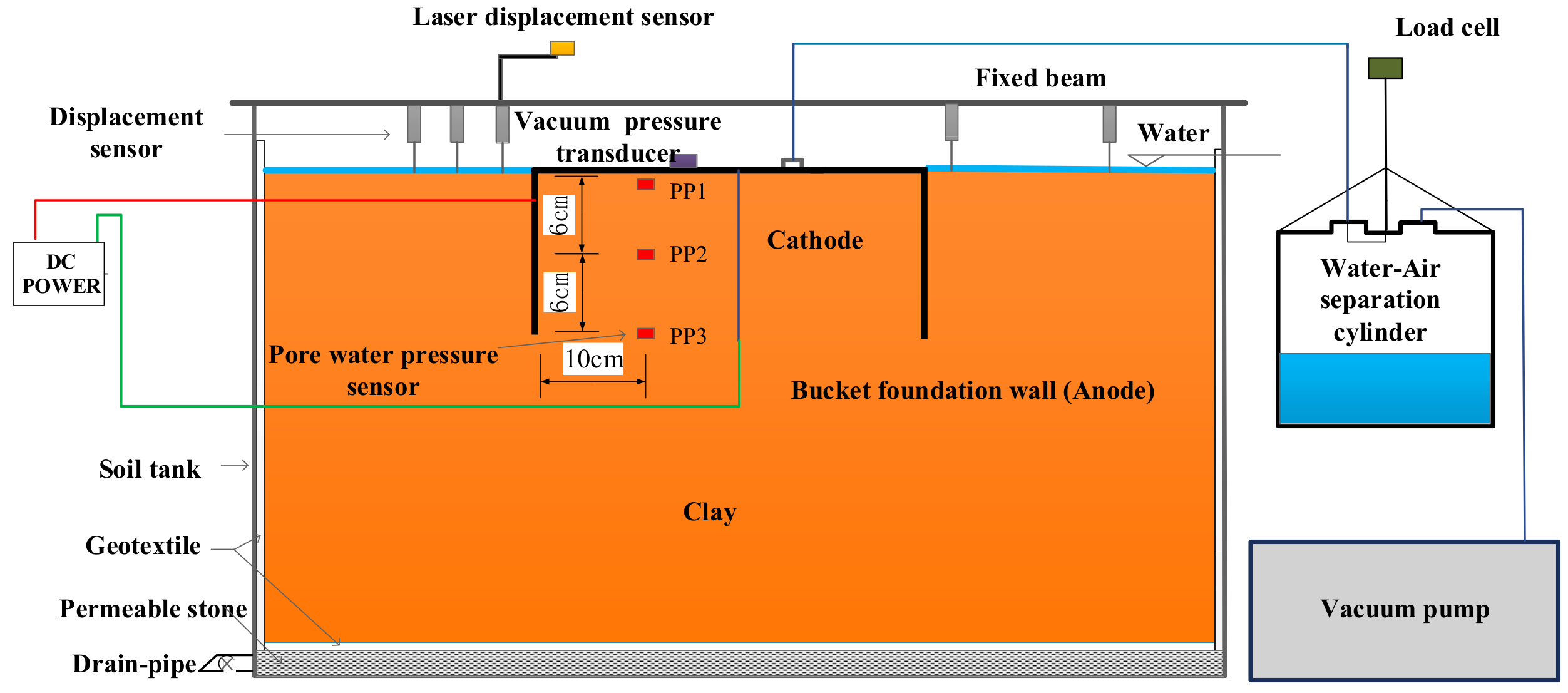
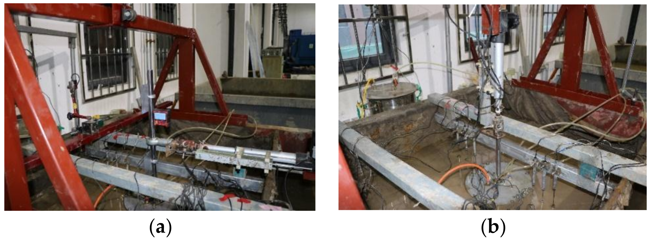
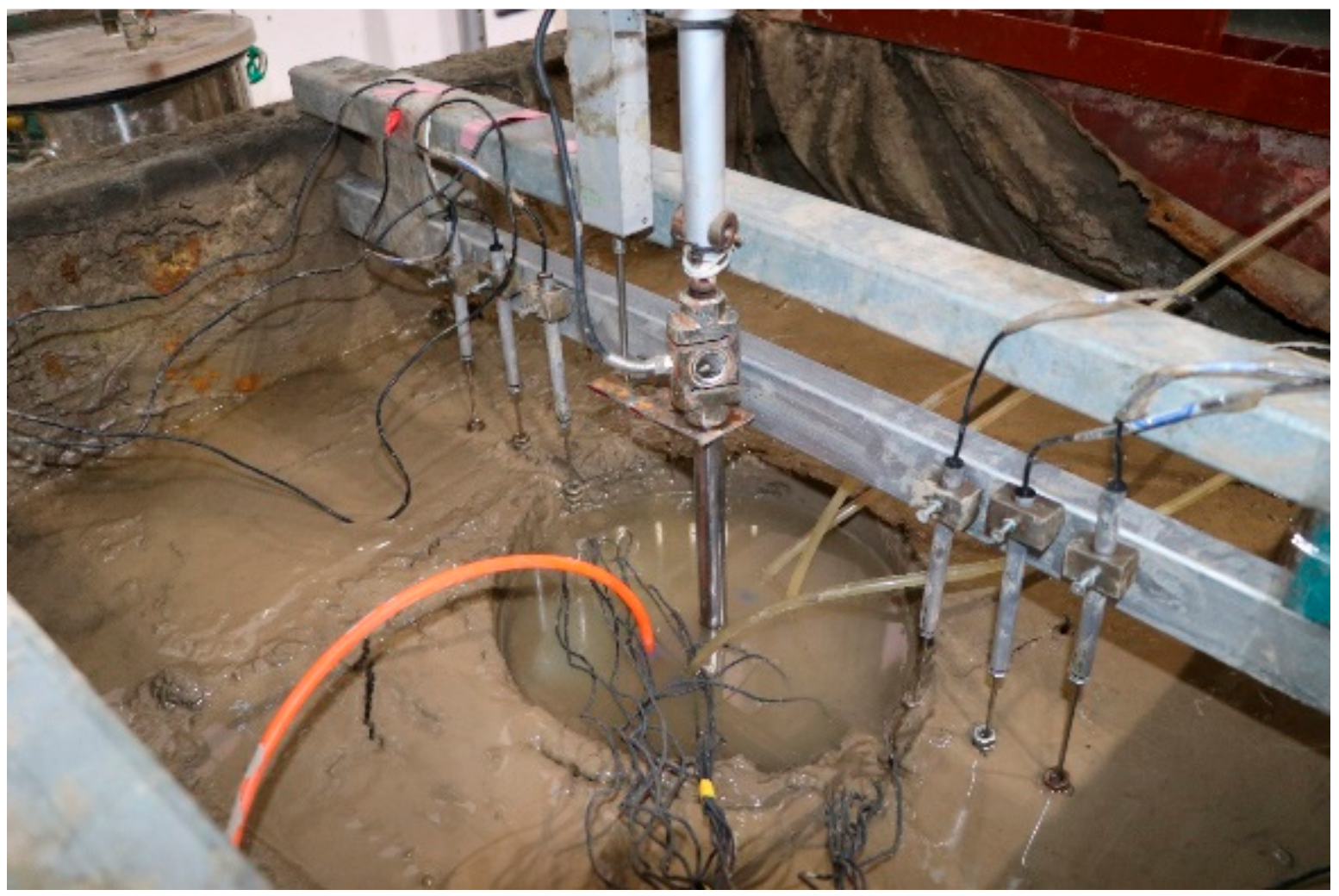
In this study, the soil tanks were 1 m long, 1 m wide, and 1 m high. A 10 cm thick layer of cobbles was placed at the bottom of the soil tank to act as a water-drainage layer, and a layer of geotextile was placed on the cobbles for soil consolidation. Figure 3 shows the soft soil used in this study, which was taken from Bohai Bay in China. The soil preparation process is as follows. First, the soil was dried and pulverized into a powder with a particle size below 0.2 mm, and the dried soil was uniformly mixed with water to produce a mud with 50% moisture content. The prepared mud was then placed in the soil tank in 10 cm thick layers with a total thickness of approximately 60 cm. The water level was kept 2 cm high after the preparation of the soil in order to ensure saturation of the soil, and the degree of saturation was 99.2%. After one week, the undrained shear strength of the clay was approximately 2 kPa. Table 1 indicates the parameters of the soil sample.

2.2. Test Setup

Figure 4 shows the bucket foundation and electrodes used in this study. The dimensions of the bucket foundation are shown in Figure 4a. The prototype of the bucket foundation which was installed in East China Sea is 30 m in diameter and 12 m in height, and the scale of the test foundation and the prototype is 1:100. As shown in Figure 4b, the top of the bucket foundation was made of Perspex and was connected to the bucket wall using eight bolts. A layer of geotextile was laid under the bucket foundation cover to facilitate the transfer of vacuum pressure in the horizontal direction. A drainage hole and monitoring hole of vacuum pressure were placed in the top of the bucket foundation. The drainage hole was connected to the water-air separation cylinder, and the monitoring hole of the vacuum pressure was connected to the vacuum pressure sensor. The bucket wall was used as an anode and connected with an external DC power using welding wire. A copper tube with a length of 12 cm, a diameter of 1cm, and a wall thickness of 2 mm was used as a cathode (Figure 4c). A layer of geotextile was wrapped outside the copper tube to facilitate drainage of the electrode. The copper tube was inserted into the clay before installation of the bucket foundation.
Figure 5 shows the test setup for the soil reinforcement. Prior to testing, pore water pressure sensors which are named PP1, PP2 and PP3, respectively, were pre-buried at 1 cm, 6 cm, and 12 cm from the surface of the soil, as well as 10 cm horizontally from the bucket wall. A vacuum sensor and a laser displacement sensor (LPS) were installed at the top of the foundation. A vacuum pump provided a 60 kPa vacuum load. A water-air separation cylinder was arranged between the vacuum pump and the foundation, and the amount of water discharge was weighed. Figure 6 shows the sketch of horizontal and vertical loading system, which is composed of servo motor, a loading push rod, a reaction force frame, a tension and pressure sensor, a displacement sensor, a universal joint head, and a guide rod.

2.3. Test Procedure

Figure 7 shows the installation process of the bucket foundation. The self-weight installation reached a depth of 3 cm. Then, the suction was applied until the foundation cap reached the clay. After installation was completed, the vacuum was applied to soil inside the bucket foundation, and simultaneously, the positive and negative electrodes of the DC power supply were, respectively, connected with the bucket wall and the copper tube. After soil reinforcement was completed, the soil in the bucket was subjected to a vane shear test and a moisture content test.
Table 2 shows all the test conditions in this study. T1 and T2 are the vacuum preloading tests. In T2, the electrodes were installed in the bucket without voltage. In T3, T4, T5 and T6 the vacuum pressure is combined with electroosmosis reinforcement, with a voltage of 3.75 V in T3, T4 and T5, and a voltage 20 V in T6. In T3 and T6, the bucket wall was used as an anode, and the bucket wall was used is a cathode in T4. The positive and negative poles of the power supply are switched every 6 h in T5.

3. Results and Discussion

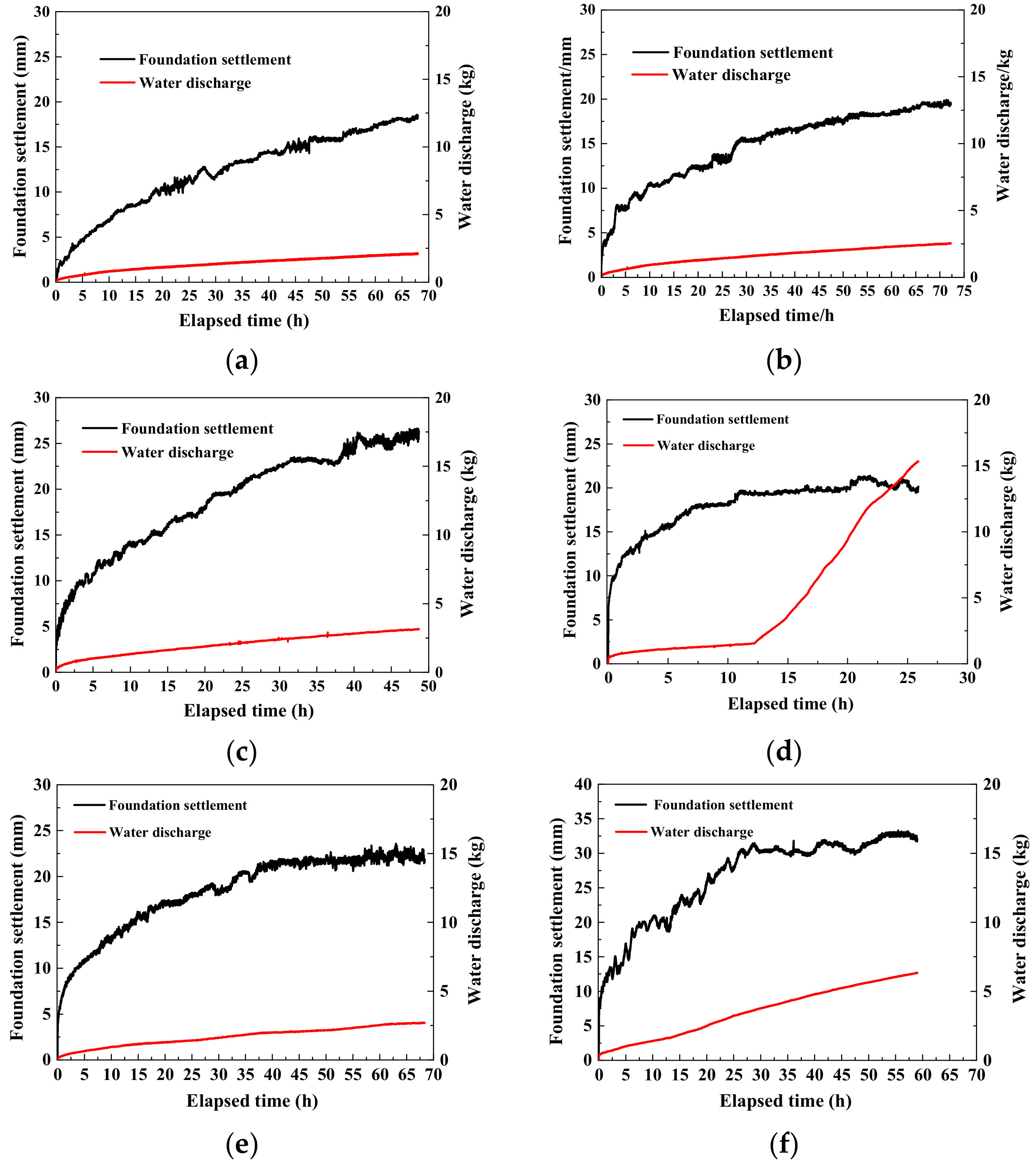
3.1. Effects of Foundation Settlement and Displacement during Soil Improvement

Figure 8 illustrates the relationship between bucket settlement and water discharge with time during the reinforcement tests. Table 3 shows the foundation settlement and drainage quality under different working conditions. In T1, T2, T3, T5, and T6, water discharge rate decreases with increasing reinforcement time. In T4, the water in the soil is collected using electroosmosis. After the soil is strengthened for approximately 12 h, percolation channels are formed on both sides of the tube wall, and the pumping volume increases rapidly. After 12 h of foundation reinforcement, the foundation reached a maximum settlement displacement of 20 mm. The through-flow passage was created due to the contact surface between the bucket wall and the internal and external soils. The pumping amount subsequently increased linearly with the reinforcement time, and the water discharge weight reached 15 kg at 25 h. The test was stopped after 27 h of operation. Based on the cumulative pumping volume of the first 2.5 h of reinforcement, the drainage quality of T4 reached a maximum of 0.924 kg, and the foundation settlement was 13.599 mm. This is primarily due to the larger surface area of the bucket wall enhancing the electro-osmotic effect compared to the copper tube anode. The moisture content of the soil inside the bucket foundation is large in the initial stage of reinforcement; hence, the reinforcement effect in T4 is best in the initial stage of reinforcement. The reinforcement effect in T1 is the weakest, with a drainage quality and foundation settlement of only 0.388 kg and 2.942 mm, respectively. After 10 h, the reinforcement effect in T6 is the best. Also, the maximum drainage quality in T6 is 1.411 kg, and the maximum settlement of foundation is 20.740 mm, which is primarily due to the large driving voltage. When reinforcement time reaches 50 h, the drainage quality in T6 reaches 5.646 kg, and the foundation settlement is up to 31.412 mm. The foundation settlement in T6 is 1.79 times that in T3, and the weight of water discharge in T6 is 1.80 times that in T3. Therefore, during vacuum piezoelectric infiltration strengthening of the bucket foundation, increasing the electro-osmotic voltage can effectively improve soil consolidation. Furthermore, the T3 foundation settlement is 1.67 times and 1.49 times that in T1 and T2, respectively, and the drainage quality is 1.76 times and 1.53 times that in T1 and T2, respectively. Test results show that the vacuum combined with electroosmosis reinforcement can effectively improve the consolidation rate of the soil inside the foundation compared to the vacuum only preloading method.

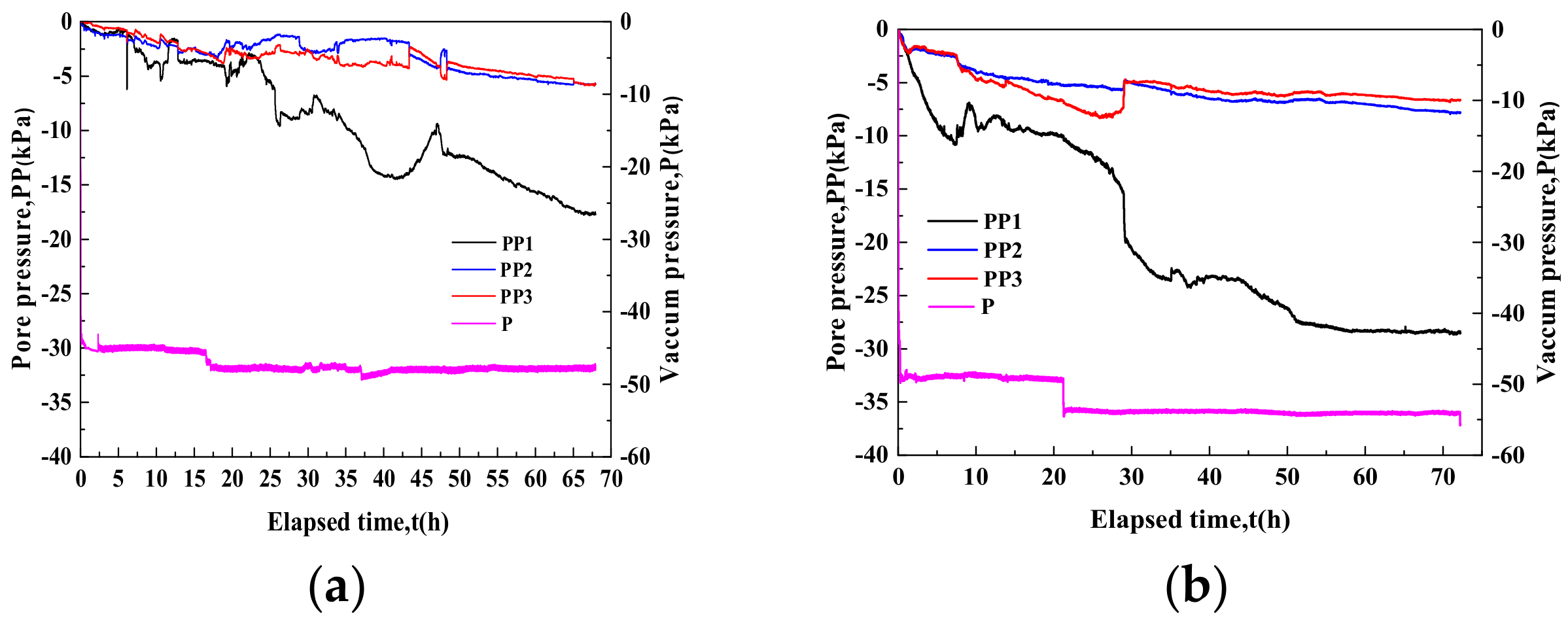
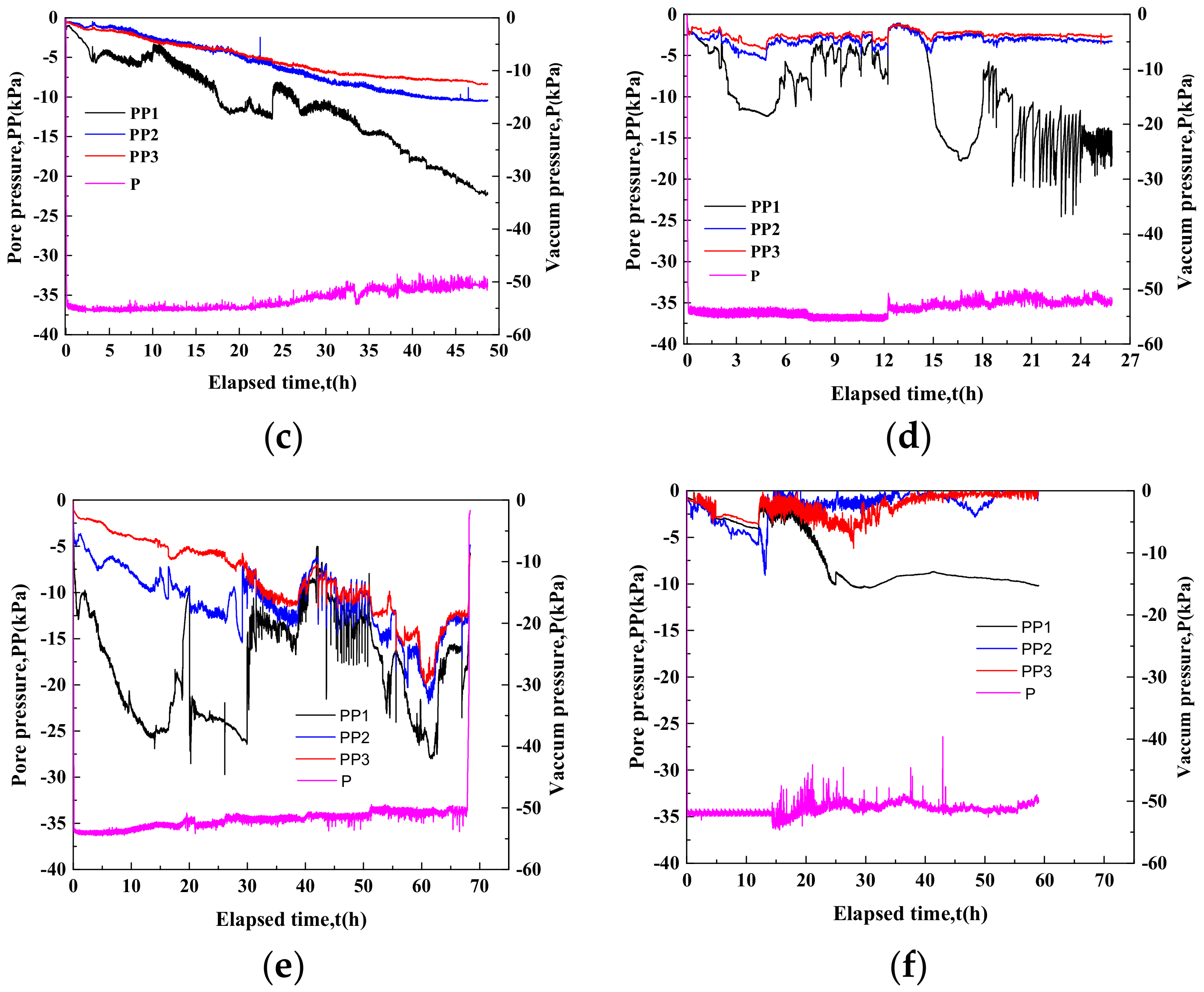
3.2. Effect of Pore Water Pressure during Soil Reinforcement

Figure 9 shows the relationship between the excess pore water pressures PP1, PP2, and PP3 and the vacuum load P for the bucket during the reinforcement process. The negative pressure beneath the bucket foundation top during the reinforcement process is approximately −50 kPa due to vacuum load loss. As shown in Figure 10, pore water pressure increases with elapsed time. PP2 and PP3 are less than −5 kPa for all tests, except T5. PP2 near the top of the foundation is −1 to −2 kPa higher than PP3. The maximum PP3 in T5 is −18 kPa, and the maximum PP2 and PP3 are −20 kPa and −18 kPa, respectively.
Compared with T1, PP1 increased by 10 kPa, and PP2 and PP3 increased by −1.5 kPa after 60 h of soil reinforcement in T2 with an additional electrode. The electrode arrangement increases the longitudinal drainage channel within the soil in the bucket, promoting the transmission of the negative pressure throughout the soil, which contributes to soil reinforcement inside the foundation. Compared with T2, PP2 and PP3 increased by −2 kPa and −10 kPa in T3 and T5 after 60 h of reinforcement, respectively. This is primarily due to the pore water in the bucket moving from the anode to the cathode under the action of electroosmosis such that the soil in the bucket generates an electric hydraulic gradient in the horizontal direction, which is superimposed on the negative vertical pressure on the foundation and increases the pore water pressure.
In T4, due to the formation of through-flow passages on both sides of the bucket wall, PP2 and PP3 in the soil are only 50% of PP2 and PP3 in T3 after 24 h of reinforcement. In T6, electrolyzed water was present inside the bucket foundation, and the moisture content rapidly decreased, forming an impervious water-repellent layer; therefore, PP2 and PP3 were close to 0 kPa at the end of T6.

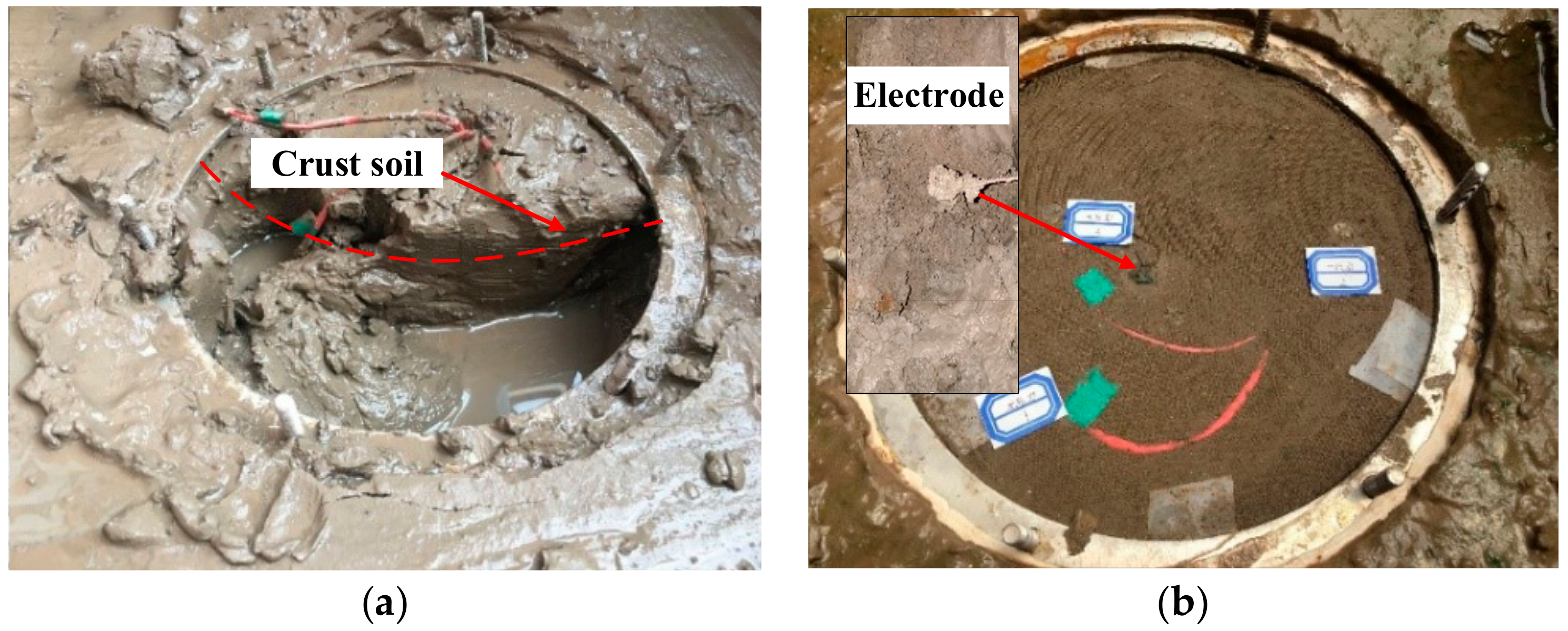
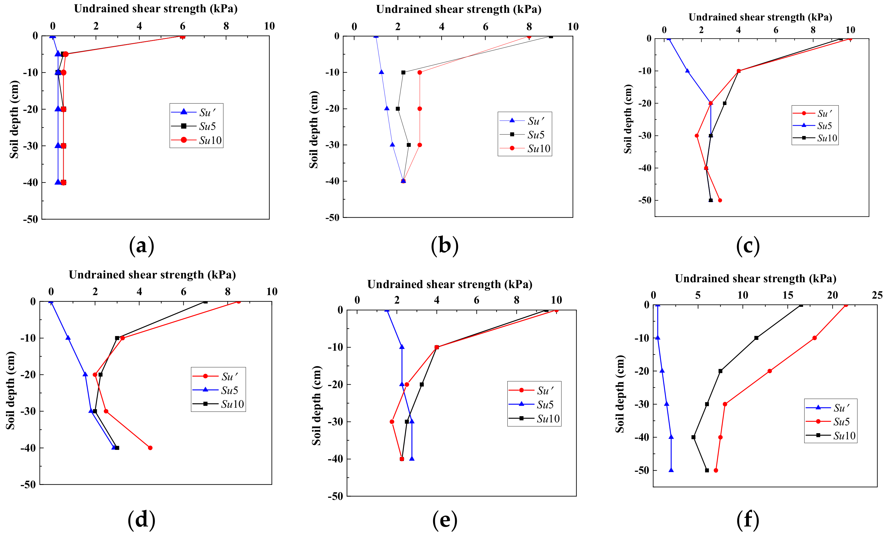
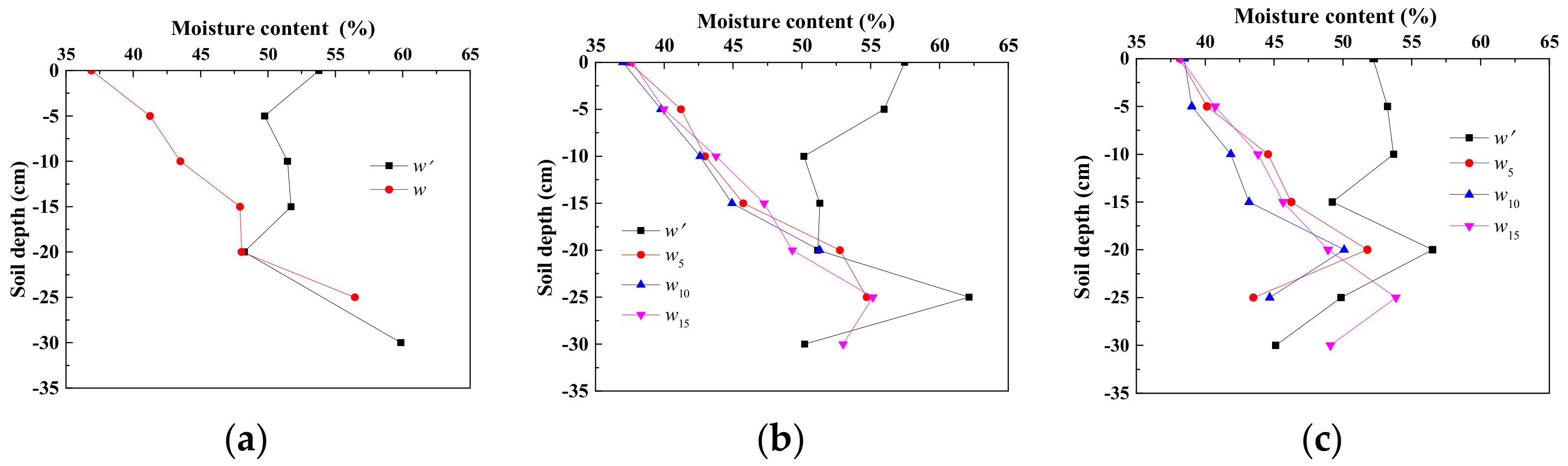
3.3. Effects of Shear Strength and Soil Moisture Content before and after Soil Reinforcement

Figure 10 shows the photos of the soil change after the soil reinforcement, and Figure 11 shows the undrained shear strength of the soil in T1-T6. Su’ means the undrained shear strength of the soil before reinforcement, and Su5, Su10, and Su15 indicate the undrained shear strength of the soil at 5 cm, 10 cm, and 15 cm from the wall of the bucket wall after reinforcement, respectively.
In T1 and T2, an ~2 cm thick crust soil was found under the bucket foundation (Figure 10a). The undrained shear strength of the crust soil was 6–8 kPa, and the water content was approximately 38%. The generation of the crust soil hinders the downward transfer of the negative pressure, restricting any change in shear strength of the soil under the crust. At a depth of 5 cm, the undrained shear strength of the soil is the same as before the reinforcement, and the moisture content of the soil is reduced by 10%. In T2, the electrode increases the vertical negative pressure transmission channel in the soil, and soil reinforcement strength in the horizontal direction is uneven. The undrained shear strength Su at 5 cm and 10 cm from the wall of the bucket increased by 1 kPa and 2 kPa, respectively.
The undrained shear strength of the surface soil is 10 kPa in T3 and T5 and 8 kPa in T4. At a depth of 10 cm in the bucket, the undrained shear strength is 4 kPa in T3 and T5 and approximately 3 kPa in T4. The undrained shear strength of T3 and T5 is about 1.67 times the height of the bucket wall.
In T6, the undrained shear strength of the soil is 21.5 kPa, which is approximately 20 times the shear strength before reinforcement, and the reinforcement depth is approximately 4 times of the foundation height. At 10 cm deep, Su5 and Su10 of the soil in the bucket are 12 kPa and 18 kPa, respectively, which are 3 times and 4.5 times the corresponding shear strengths in T3. Su10 is about 3 kPa greater than Su5. The soil near the cathode has the highest undrained shear strength. After the test, the soil in the bucket is in a hard plastic state and is wrapped tightly around the cathode (Figure 10b).
Figure 12 shows the change in moisture content with soil depth, where w’, w5, w10, and w15, respectively indicate the moisture content of the soil before reinforcement, at 5 cm, 10 cm, and 15 cm from the bucket wall after reinforcement. The soil has a moisture content of approximately 50% before reinforcement and a moisture content of approximately 55% in the surface soil. In T1-T5, the moisture content at 5 cm deep after soil reinforcement decreases to 40%, and the soil moisture content is about 50% at 20 cm deep, which is the same as soil without reinforcement. Due to the hard soil in the upper part of T6, moisture content was only measured up to 20 cm deep, and the soil moisture content was approximately 38%. Therefore, increasing the driving voltage can effectively decrease moisture content and increase the uniformity of the soil reinforcement in the vertical direction.
In this study, the vacuum-electroosmosis reinforcement tests of the bucket foundation under atmospheric conditions were carried out. The vacuum load was the atmospheric pressure difference between the top and bottom top lid, therefore, the maximum vacuum load applied was −100 kPa. Furthermore, the situ effects with high confining pressure under the water will be occurred, and the high water level will promote the vacuum load. The under-pressure of the top lid will be increased with the increased water depth. For example, it could create a gradient of −200 kPa (−100 kPa is initial pore water pressure and extra −100 kPa is the cavitation limit) at 10 m depth. Therefore, the soil reinforcement will be more efficacious.
In actual foundation of the offshore wind turbine. A cathode hole can be installed on the top lid of the bucket foundation, and the hole can be sealed during the installation and the vacuum electroosmosis soil reinforcement. After the installation of the bucket foundation, the electrokinetic geosynthetics (EKG) will be inserted through the cathode hole, which is used as cathode, and then seal the cathode hole. The bucket wall will be connected with positive pole of the DC power, and the EKG will be connected with the negative pole of the DC power. Then the vacuum preloading will be applied through the pumping hole. Therefore, the soil inside the bucket foundation will be reinforced. The voltage gradient applied with 1.3 V/cm will be more efficacious than 0.25 V/cm, and the bucket wall should be used as anode during the reinforcement.

4. Bucket Foundation Bearing Capacity before and after Soil Reinforcement

The reinforcement method of the soil employed in this study is the same as in T6. After soil reinforcement, the horizontal and vertical bearing capacities of the bucket foundation were measured.

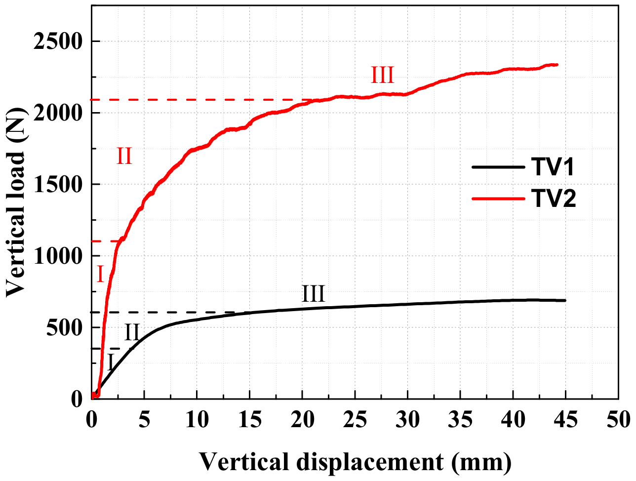
4.1. Influence of Soil Reinforcement on Bucket Foundation Vertical Bearing Capacity

Under a vertical load, the bucket foundation experiences general shear failure with significant soil heave around the foundation (Figure 13). In this test, the vertical load corresponding to a vertical displacement of 0.07 D is used as the vertical bearing capacity of the bucket foundation, which gives a soil vertical bearing capacity before and after reinforcement of 675 N and 2085 N, respectively. The vertical bearing capacity increased by 2.1 times after reinforcement. The vertical load-displacement curve can be divided into three stages, including the compression stage I, shear stage II, and heave stage III (Figure 14). In the compression phase I, the load-displacement curve is approximately straight during elastic deformation, and the stiffness of the vertical load is 0.130 MN/m without reinforcement, and 0.423 MN/m after reinforcement. The vertical bearing stiffness of the foundation after reinforcement is 3.25 times that of the unreinforced soil. In the shear stage II, the load-displacement curve is nonlinear, and shear occurs at the bottom of the foundation. Test results show that the vertical displacement in the shear stage is approximately 12 mm before reinforcement and increases to 17.5 mm after reinforcement. In the heave stage III, an incremental load increase will cause a large foundation settlement. In this stage, the vertical load growth rate is 6.23 kN/m for soil without reinforcement and 9.40 kN/m for reinforced soil. The vertical bearing capacity and stability of the bucket foundation as well as soil stiffness are significantly improved after vacuum-electro-osmotic reinforcement.

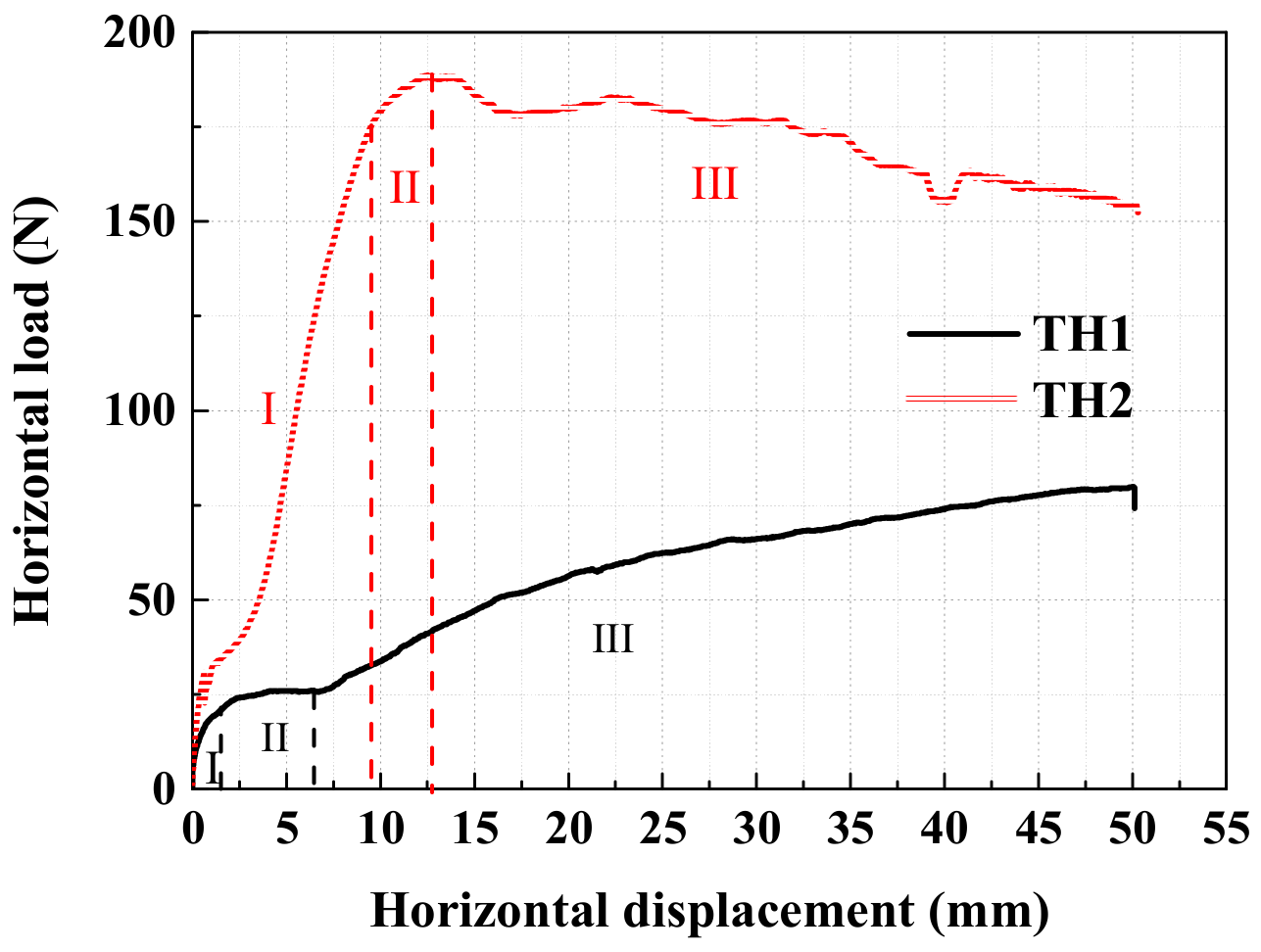
4.2. Influence of Soil Reinforcement on Bucket Foundation Horizontal Bearing Capacity

The bucket foundation undergoes forward deflection under a horizontal load, and a gap was present on the back side of the foundation after soil reinforcement in the bucket (Figure 15). The horizontal load corresponding to the horizontal displacement of the foundation is determined by a horizontal displacement of 0.05 D, therefore, the horizontal bearing capacity of the test before and after reinforcement was 47.1 N and 184 N, respectively (Figure 16). The bearing capacity of the soil was increased by 2.9 times. The horizontal load displacement curve can be divided into three stages, including the elastic stage, elastoplastic stage, and plastic failure stage (Figure 16). The load-displacement curve is approximately linear in the elastic stage. The stiffness of the horizontal load before and after soil reinforcement is 18.35 kN/m and 14 kN/m, respectively, and the elastic stage has displacements of 21 mm and 1.5 mm, respectively. The final horizontal resistance is 174.4 N and 21 N, respectively, and the horizontal resistance of the bucket after the elastic stage is 8.3 times that of the non-reinforced condition. In the elastoplastic stage, the soil plastic deformation load displacement curve is nonlinear. When the soil in the bucket is reinforced, the soil shear stress gradually reaches its failure strength, and the soil enters a plastic limit equilibrium state. In the plastic failure stage, shear failure of the soil occurs after reinforcement, and the resistance provided by the soil plastic deformation outside the bucket is much less than the horizontal resistance provided by the reinforced soil within the bucket, which significantly reduces the horizontal bearing capacity. However, the horizontal resistance without soil reinforcement is increased by the soil plastic deformation, but the large deformation of the foundation does not meet the design criteria.

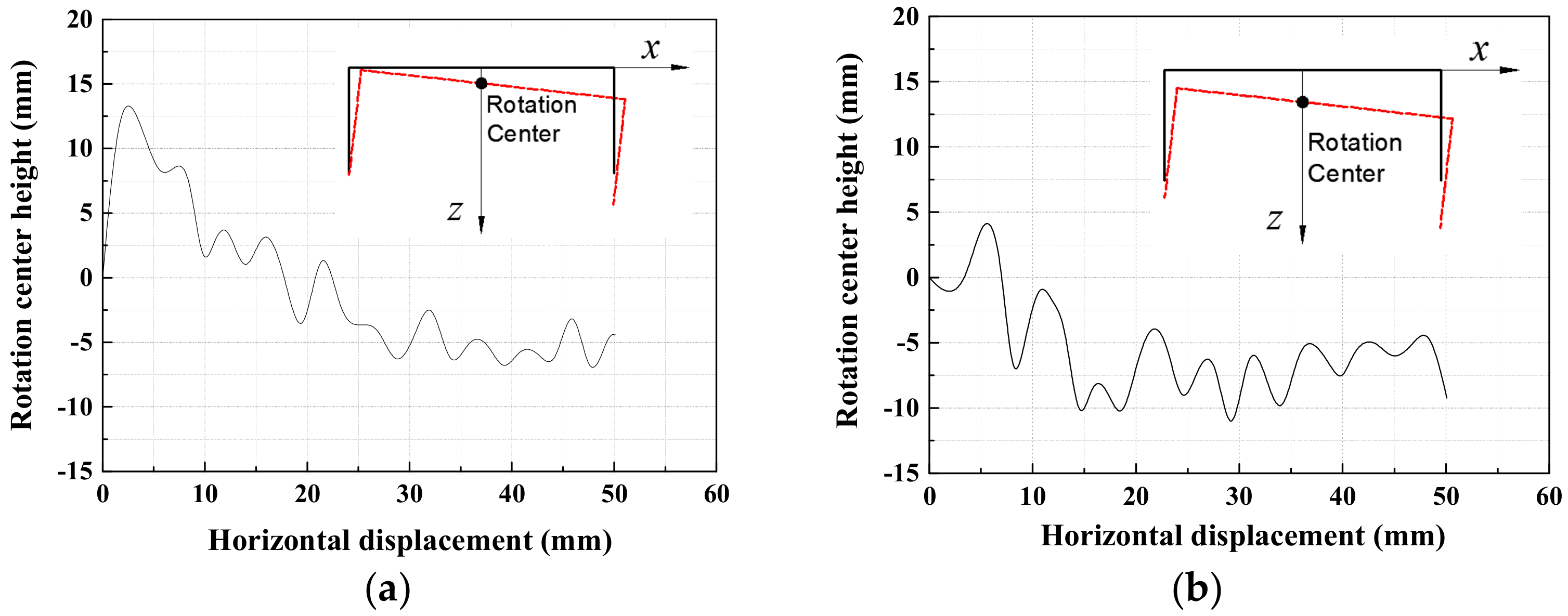
4.3. Influence of Soil Reinforcement on Rotation Centers

Figure 17 shows the relationship between the rotation point height and bucket foundation horizontal displacement before and after the soil reinforcement. Results indicate that the center of rotation is the highest when the horizontal displacement is less than 5 mm, and the bucket foundation rotation height increases with increasing horizontal displacement, after which the height of rotation point gradually decreases. When the horizontal displacement is 15 mm, the height of the center of rotation is 2 mm on the mud surface and 10 mm below the mud surface before and after reinforcement, respectively. After soil reinforcement, the passive earth pressure in the passive zone provides greater resistance for the soil reinforcement, therefore, the height of the rotation center after soil reinforcement is significantly lower than that before soil reinforcement.

5. Conclusions

The influence of vacuum pressure, the electrodes, and electrification mode on the strengthening of soil in a bucket foundation was examined using model tests of vacuum electroosmosis reinforcement. The effects of reinforcement on foundation settlement, water discharge, and undrained shear strength were evaluated. Finally, model tests on bearing capacity of the bucket foundation before and after soil reinforcement were carried out, and the effects of soil reinforcement on the bearing characteristics of the bucket foundation were analyzed. The following conclusions are made:
(1)
The vacuum electroosmosis reinforcement significantly improves soil strength inside the bucket foundation when using the bucket wall as the anode, and undrained shear strength increases with increasing the voltage. The undrained shear strength of the soil applied the voltage of 20 V is 3–4.5 times that applied the voltage of 3.75 V in this study. Furthermore, a higher driving voltage can improve the uniformity of soil reinforcement in the vertical direction. The vertical bearing stiffness of the reinforced foundation during soil compression is 3.25 times the bearing stiffness of an unreinforced foundation.
(2)
Using the bucket wall as the cathode causes a percolation passage along the bucket wall to form, which decreases the reinforcement effect. The strengthening effect of the conversion electrode method was weaker than using the bucket wall as the anode. In addition, increased internal vertical drainage channel during the reinforcement can effectively improve vacuum pressure transmission inside the soil, thereby improving the reinforcement.
(3)
The horizontal and vertical bearing capacity of bucket foundation can be significantly increased through vacuum electroosmosis reinforcement. General shear failure of the bucket foundation occurs under vertical load. The vertical bearing stiffness of the reinforced foundation during soil compression is 3.25 times the bearing stiffness of an unreinforced foundation, and the vertical bearing capacity of the foundation increased by 2.1 times after soil reinforcement.
(4)
The bucket foundation undergoes forward destructive failure when subjected to horizontal load. In the elastic stage, the horizontal resistance of the reinforced foundation is 8.3 times that of the unreinforced foundation, and the horizontal bearing capacity increased by 2.9 times. Soil reinforcement improves the stiffness of the soil and the passive earth pressure; thus, the height of the rotation center is significantly reduced after soil reinforcement.

Author Contributions

Conceptualization, H.D. and P.Z.; methodology, H.D., P.Z. and H.Z.; validation, P.Z. and H.Z.; formal analysis, H.Z. and P.Z.; data curation, C.L. and P.Z.; writing—original draft preparation, H.Z.; writing—review and editing, P.Z., H.Z. and C.L.; funding acquisition, H.D., P.Z and C.L.

Funding

This research was supported by the National Natural Science Foundation of China (No. 51779171, No.51679163), Innovation Method Fund of China (No. 2016IM030100), Tianjin Municipal Natural Science Foundation (No. 17JCYBJC22000).

Conflicts of Interest

The authors declare no conflict of interest.

References

  1. Byrne, B.W.; Houlsby, G.T. Foundations for offshore wind turbines. Phil. Trans. Roy. Soc. Lond. Math. Phys. Eng. 2003, 361, 2909–2930. [Google Scholar] [CrossRef] [PubMed]
  2. Liu, R.; Zhou, L.; Lian, J.J.; Ding, H.Y. Behavior of monopile foundations for offshore wind farms in sand. J. Waterw. Port Coast. Ocean Eng. 2016, 142, 1–11. [Google Scholar] [CrossRef]
  3. Bienen, B.; Gaudin, C.; Cassidy, M.J.; Rausch, L.; Purwana, O.A.; Krisdani, H. Numerical modelling of a hybrid skirted foundation under combined loading. Comput. Geotech. 2012, 45, 127–139. [Google Scholar] [CrossRef]
  4. Fiumana, N.; Bienen, B.; Govoni, L.; Gourvenec, S.; Cassidy, M.J.; Gottardi, G. Combined loading capacity of skirted circular foundations in loose sand. Ocean Eng. 2019, 183, 57–72. [Google Scholar] [CrossRef]
  5. Kim, D.J.; Choo, Y.W.; Kim, J.H.; Kim, S.; Kim, D.S. Investigation of monotonic and cyclic behavior of tripod suction bucket foundations for offshore wind towers using centrifuge modeling. J. Geotech. Geoenviron. 2014, 140, 1–10. [Google Scholar] [CrossRef]
  6. Li, D.; Zhang, Y.; Feng, L.; Gao, Y. Capacity of modified suction caissons in marine sand under static horizontal loading. Ocean Eng. 2015, 102, 1–16. [Google Scholar] [CrossRef]
  7. Wang, X.; Yang, X.; Zeng, X. Centrifuge modeling of lateral bearing behavior of offshore wind turbine with suction bucket foundation in sand. Ocean Eng. 2017, 139, 140–151. [Google Scholar] [CrossRef]
  8. Zhang, P.; Guo, Y.; Liu, Y.; Ding, H. Experimental study on installation of hybrid bucket foundations for offshore wind turbines in silty clay. Ocean Eng. 2016, 114, 87–100. [Google Scholar] [CrossRef]
  9. First Suction Bucket Jacket Foundation Installed at EOWDC. Available online: https://www.geplus.co.uk /news/first-suction-bucket-jacket-foundation-installed-at-eowdc/10029529.article (accessed on 27 May 2019).
  10. Ding, H.; Liu, Y.; Zhang, P.; Le, C. Model tests on the bearing capacity of wide-shallow composite bucket foundations for offshore wind turbines in clay. Ocean Eng. 2015, 103, 114–122. [Google Scholar] [CrossRef]
  11. Zhang, P.; Zhang, Z.; Liu, Y.; Ding, H. Experimental study on installation of composite bucket foundations for offshore wind turbines in silty sand. J. Offshore Mech. Arct. Eng. 2016, 138, 1–11. [Google Scholar] [CrossRef]
  12. Zhang, P.; Han, Y.; Ding, H.; Zhang, S. Field experiments on wet tows of an integrated transportation and installation vessel with two bucket foundations for offshore wind turbines. Ocean Eng. 2015, 108, 769–777. [Google Scholar] [CrossRef]
  13. Senders, M. Suction Caissons in Sand as Tripod Foundations for Offshore Wind Turbines. Ph.D. Thesis, The University of Western Australia, Perth, Australia, 2008. [Google Scholar]
  14. Cotter, O. The Installation of Suction Caisson Foundations for Offshore Renewable Energy Structures. Ph.D. Thesis, University of Oxford, Oxford, UK, 2009. [Google Scholar]
  15. Zhang, P.; Ding, H.; Le, C. Installation and removal records of field trials for two mooring dolphin platforms with three suction caissons. J. Waterw. Port Coast. Ocean Eng. 2013, 139, 502–517. [Google Scholar] [CrossRef]
  16. Zhang, P.; Ding, H.; Le, C. Model tests on tilt adjustment techniques for a mooring dolphin platform with three suction caisson foundations in clay. Ocean Eng. 2013, 73, 96–105. [Google Scholar] [CrossRef]
  17. Ding, H.; Li, Z.; Lian, J.; Zhang, P.; Huang, X. Soil reinforcement experiment inside large-scale bucket foundation in muddy soil. Trans. Tianjin Univ. 2012, 18, 168–172. [Google Scholar] [CrossRef]
  18. Ding, H.; Liu, Y.; Zhang, P. Negative pressure consolidation of silt inside bucket foundation. Trans. Tianjin Univ. 2015, 21, 333–340. [Google Scholar] [CrossRef]
  19. Zhang, P.; Ding, H.; Zhai, S.; Xiong, K. Test on muddy soil reinforcement by negative pressure and electroosmosis inside cover-bearing-type bucket foundation for offshore wind turbines. Trans. Tianjin Univ. 2013, 19, 10–16. [Google Scholar] [CrossRef]
  20. Le, C.; Ding, H.; Zhang, Y. Experimental study of muddy soil inside bucket foundation using vacuum electro-osmotic reinforcement. J. Dalian Univ. Technol. 2013, 53, 97–101. [Google Scholar]
  21. Holtan, G.W. Vacuum stabilization of subsoil beneath runway extension at Philadelphia International Airport. In Proceedings of the 6th International Conference of Soil Mechanics & Foundation Engineering (ICSMFE), 8–15 September 1965; Volume 2, pp. 61–65. [Google Scholar]
  22. Chu, J.; Yan, S.W.; Yang, H. Soil improvement by the vacuum preloading method for an oil storage station. Geotechnique 2000, 50, 625–632. [Google Scholar] [CrossRef]
  23. Chu, J.; Guo, W.; Lam, K.P.; Yan, S. Use of clay slurry and waste for land reclamation. In Proceedings of the 18th Southeast Asian Geotechnical & Inaugural (AGSSEA) Conference, Singapore, 29–31 May 2013; pp. 755–760. [Google Scholar]
  24. Bergado, D.T.; Balasubramaniam, A.S.; Fannin, R.J.; Holtz, R.D. Prefabricated vertical drains (pvds) in soft Bangkok clay: A case study of the new Bangkok International Airport project. Can. Geotech. 2002, 39, 304–315. [Google Scholar] [CrossRef]
  25. Doyle, K.; Qiu, T. Piecewise-Linear modeling of combined vacuum and surcharge preloading at the second Bangkok International Airport. Geo Chic. 2016, 2016, 836–844. [Google Scholar]
  26. Gouw, T.L. Soil improvement by vacuum preloading for a power plant project in Vietnam. In Proceedings of the 18th Southeast Asian Geotechnical & Inaugural (AGSSEA) Conference, Singapore, 29–31 May 2013. [Google Scholar]
  27. Indraratna, B.; Rujikiatkamjorn, C.; Zhong, R. Recent developments of vacuum-assisted consolidation of soft estuarine clays. Geotech. Struct. Eng. Congr. 2016, 2016, 950–959. [Google Scholar]
  28. Rujikiatkamjorn, C.; Indraratna, B. Current state of the art in vacuum preloading for stabilizing soft soil. Geotech. Eng. J. 2013, 44, 77–87. [Google Scholar]
  29. Long, P.V.; Nguyen, L.V.; Bergado, D.T.; Balasubramaniam, A.S. Performance of PVD improved soft ground using vacuum consolidation methods with and without airtight membrane. Geotex. Geomembr. 2015, 43, 473–483. [Google Scholar] [CrossRef]
  30. Cassagrande, I.L. Electroosmosis in soils. Geotechnique 1949, 1, 159–177. [Google Scholar] [CrossRef]
  31. Cassagrande, I.L. Stabilization of soils by means of electroosmosis—State-of-the-art. J. Boston Soc. Civ. Eng. 1983, 69, 255–302. [Google Scholar]
  32. Esrig, M.I. Pore pressures, consolidation, and electrokinetics. J. Soil Mech. Found. Div. 1968, 94, 899–920. [Google Scholar]
  33. Burnotte, F.; Lefebvre, G.; Grondin, G. A case record of electroosmotic consolidation of soft clay with improved soil–electrode contact. Can. Geotech. J. 2004, 41, 1038–1053. [Google Scholar] [CrossRef]
  34. Chien, S.C.; Ou, C.Y.; Wang, M.K. Injection of saline solutions to improve the electro-osmotic pressure and consolidation of foundation soil. Appl. Clay Sci. 2009, 44, 218–224. [Google Scholar] [CrossRef]
  35. Cardoso, R.; Santos, J.N. Experimental study on the use of electroosmosis for accelerating the consolidation of clays under increasing vertical stress. In Proceedings of the 5th BIOT Conference on Poromechanics, Vienna, Austria, 10–12 July 2013; pp. 1515–1523. [Google Scholar]
  36. Wu, H.; Hu, L.; Qi, W.; Wen, Q. Analytical solution for electro-osmotic consolidation considering nonlinear variation of soil parameters. Int. J. Geomech. 2016, 17, 060160321–060160329. [Google Scholar]
Figure 1. The composite bucket foundation (CBF) with offshore wind turbine: (a) Prefabrication onshore; (b) One-step transportation; (c) Integrated installation.
Applsci 09 03778 g001
Figure 2. Soil failure during the installation of a bucket foundation: (a) Soil plug during installation (b) Fractures beside the bucket wall [16].
Applsci 09 03778 g002
Figure 3. Soil sample and vane shear test.
Applsci 09 03778 g003
Figure 4. Test model and electrode: (a) Sketch of the bucket foundation; (b) Bucket foundation; (c) Copper tube electrode.
Applsci 09 03778 g004
Figure 5. Vacuum pressure combined electro-osmotic reinforcement device.
Applsci 09 03778 g005
Figure 6. Bearing capacity test system of bucket foundation: (a) Horizontal loading test system; (b) Vertical loading test system.
Applsci 09 03778 g006
Figure 7. Installation of bucket foundation: (a) Self-weight installation; (b) Suction installation.
Applsci 09 03778 g007
Figure 8. Foundation settlement and water discharge versus reinforcement time: (a) Test T1; (b) Test T2; (c) Test T3; (d) Test T4; (e) Test T5; (f) Test T6.
Applsci 09 03778 g008
Figure 9. Pore pressure, vacuum load versus time: (a) Test T1; (b) Test T2; (c) Test T3; (d) Test T4; (e) Test T5; (f) Test T6.
Applsci 09 03778 g009aApplsci 09 03778 g009b
Figure 10. Photographs showing the soil change inside the bucket foundation: (a) Test T1; (b) Test T6.
Applsci 09 03778 g010
Figure 11. Undrained shear strength with soil depth for T1–T6: (a) Test T1; (b) Test T2; (c) Test T3; (d) Test T4; (e) Test T5; (f) Test T6.
Applsci 09 03778 g011
Figure 12. Changes of moisture content with soil depth for T1–T6: (a) Test T1; (b) Test T2; (c) Test T3; (d) Test T4; (e) Test T5; (f) Test T6.
Applsci 09 03778 g012aApplsci 09 03778 g012b
Figure 13. Failure mode of vertical load.
Applsci 09 03778 g013
Figure 14. Vertical load versus displacement.
Applsci 09 03778 g014
Figure 15. Failure mode of horizontal load.
Applsci 09 03778 g015
Figure 16. Horizontal load versus displacement.
Applsci 09 03778 g016
Figure 17. Rotation center height versus horizontal displacement: (a) TH1; (b) TH2.
Applsci 09 03778 g017
Table 1. Physical and mechanical parameters of soil.
Soil TypeMoisture Content w (%)Plastic Limit wp (%)Liquidity Index IL (%)Plasticity Index IPShear Strength Su (kPa)Permeability Coefficient k (cm·s−1)Unit Weight γ (kN·m−3)Coefficient of Compressibility a (MPa−1)
Clay502237151~26.7 × 10−617.20.91
Table 2. Test conditions.
Test Nos.Vacuum Loading (kPa)Voltage (V)Reinforcement Time (h)Bucket Wall ElectrodeCopper Rod Electrode
T160070——No
T260070——Yes
T3603.7570AnodeYes
T4603.7527CathodeYes
T5603.7570A ↔ C *Yes
T6602070AnodeYes
TV1——————————
TH1——————————
TV2602070AnodeYes
TH2602070AnodeYes
* A ↔ C means electrode exchange during the test.
Table 3. Settlement and water discharge of foundation at different reinforcement time.
Test Nos2.5 h10 h50 h
Settlement (mm)Water Discharge (kg)Settlement (mm)Water Discharge (kg)Settlement (mm)Water Discharge (kg)
T12.9420.3886.9410.78215.6591.786
T25.4710.45410.5060.92217.5222.054
T38.6140.79614.1331.33926.189 *3.143 *
T413.5990.92418.1051.410--
T59.1500.47113.2470.94721.8132.158
T611.8640.70620.7401.41131.4125.646
* The soil improvement time is 48.7 h.

