Article

Enhancement of Corrosion Resistance of Aluminum 7075 Surface through Oil Impregnation for Subsea Application

1
Offshore Industries R & BD Center, Korea Research Institute of Ships & Ocean Engineering (KRISO), Geoje 53201, Korea
2
Maritime Safety and Environmental Research Division, Korea Research Institute of Ships & Ocean Engineering (KRISO), Daejeon 34103, Korea
3
School of Mechanical Engineering, Chung-Ang University, Seoul 06974, Korea
*
Author to whom correspondence should be addressed.
Appl. Sci. 2019, 9(18), 3762; https://doi.org/10.3390/app9183762
Submission received: 6 August 2019 / Revised: 28 August 2019 / Accepted: 29 August 2019 / Published: 9 September 2019
(This article belongs to the Special Issue Advances in Organic Corrosion Inhibitors and Protective Coatings)

Abstract

:
This study investigated the corrosion resistance of oil impregnated anodic aluminum oxide (AAO) surfaces of aluminum 7075 for subsea application. Although aluminum 7075 has high strength, it is scarcely used in the subsea industry because of its corrosion issue. Some treatment of aluminum 7075 is required for subsea application. In this study not only a plate shape but also a cylindrical shape were investigated because a cylindrical shape is frequently used in the subsea industry for electronic device housing. Contact angles of bare aluminum and oil impregnated AAO surfaces of aluminum 7075 were measured after a salt spray test and a pressure test. The results showed that the contact angle of bare aluminum was considerably decreased after the salt spray test, whereas the oil impregnated AAO surface presented a relatively high contact angle after the salt spray test and the pressure test. These results showed that the corrosion resistance of aluminum 7075 could be enhanced by oil impregnation on the AAO surface, and thus can be utilized in the subsea industry.

1. Introduction

Aluminum alloy is one of the most widely used materials in the subsea industry because of its low cost, excellent thermal conductivity, good strength, acceptability for short-term development, and low density. The main reason for use in the subsea industry is the excellent thermal conductivity. The generated heat in subsea electronic equipment should be removed to prevent thermal deformation. The produced heat can be eliminated by high thermal conductivity materials by exchanging the heat with the surroundings.
There are eight series of aluminum alloys depending on its composition elements. The broadly used aluminum alloys in the subsea industry are 6000 series. The 6000 series has moderate strength, and is resistant to corrosion. The 7000 series has the highest strength among all the series, but it requires some treatment for the corrosion issue. Although the 7000 series has higher strength than the 6000 series, the 6000 series is more frequently used in the subsea industry.
Several methods have been suggested to prevent aluminum corrosion such as electrodeposition of cerium or silane films, cathodic protection using an Mg-rich coating, organic coating, conversion coating, and polymer coating [1,2,3,4,5,6]. Anodizing (Anodic Aluminum Oxide, AAO) is considered one of the most practical methods for corrosion protection. Anodizing forms a nanoporous oxide layer on the top of the aluminum surface. The well-established nanoporous structure increases the corrosion resistance. The dimensions of the nanoporous structure like pore diameter, interpore distance, and thickness of the nanoporous oxide layer can be controlled by changing the type and concentration of the acid electrolyte solution, anodic voltage, anodizing time, and temperature [7,8,9,10,11,12,13]. The anodizing time affects the pore depth, and the anodic voltage and the temperature of the electrolyte solution influence the pore diameter and the interpore distance [14]. S.-K. Hwang et al. [13] experimentally showed that the anodizing time determines the pore depth. The pore diameter is an important characteristic of the nanoporous oxide layer [15,16]. The pore diameter can be enlarged through an etching process [12,17].
A corrosive medium can permeate the pores in the produced nanoporous structure [18,19,20]. Several solutions have been suggested to prevent absorbing the corrosive medium. One method is to fill the pores with solid-state oxide materials such as hydrothermal, dichromate, and nickel-salt [18,21,22]. Another solution is the coating because the hydrophobic coatings on the hydrophilic metallic surface make the surface superhydrophobic [23,24,25,26,27]. A further solution is oil impregnation.
Oil impregnation into the nanoporous oxide layer is suggested for corrosion protection and self-healing to withstand external damages or local defects using high purity aluminum [28]. Several studies have shown that the retention of oil on the surface resisted ingress of water or organic liquid [29,30]. The marine industry has employed oil impregnation into the porous structure to prevent corrosion of the material in a marine environment using high purity aluminum, 5000 series aluminum and low alloy steel [31,32,33,34]. Some studies have indicated that the oil impregnated nanoporous oxide layer is likely to lose the oil under a dynamic environment [35].
Although several studies have investigated oil impregnation into the nanoporous oxide layer using pure aluminum or 6000 series aluminum for corrosion protection, no studies have analyzed the oil impregnated nanoporous oxide layer using 7000 series aluminum, to our best knowledge. There are no studies on conducting a pressure test for the oil-impregnated nanoporous oxide to investigate the influence of high-pressure conditions. Therefore, this study investigated the corrosion resistance of aluminum 7075 surfaces with an oil impregnated nanoporous oxide layer to enhance its corrosion resistance for subsea application. The structure of this study is as follows. The experiment for the oil impregnated nanoporous oxide layer is described including information on the materials, preparation of the AAO surface, oil impregnation on the AAO surface, a salt spray test, a pressure test, and characterization in Section 2. The results and discussion are indicated in Section 3. Finally, the conclusion is presented.

2. Experimental

2.1. Material

Commercial aluminum alloy 7075 was employed as the material for the AAO surface because it is widely used in the 7000 series aluminum. Components of aluminum 7075 are aluminum (87.1–91.4 wt%), zinc (5.1–6.1 wt%), magnesium (2.1–2.9 wt%), copper (1.2–2 wt%), chromium (0.18–0.28 wt%), iron (Max 0.5 wt%), silicon (Max 0.4 wt%), manganese (Max 0.3 wt%), titanium (max 0.2 wt%), and other total (max 0.15 wt%). Its density is approximately 2.81 g/cc. The ultimate tensile and the tensile yield strengths are 572 MPa and 503 MPa, respectively.

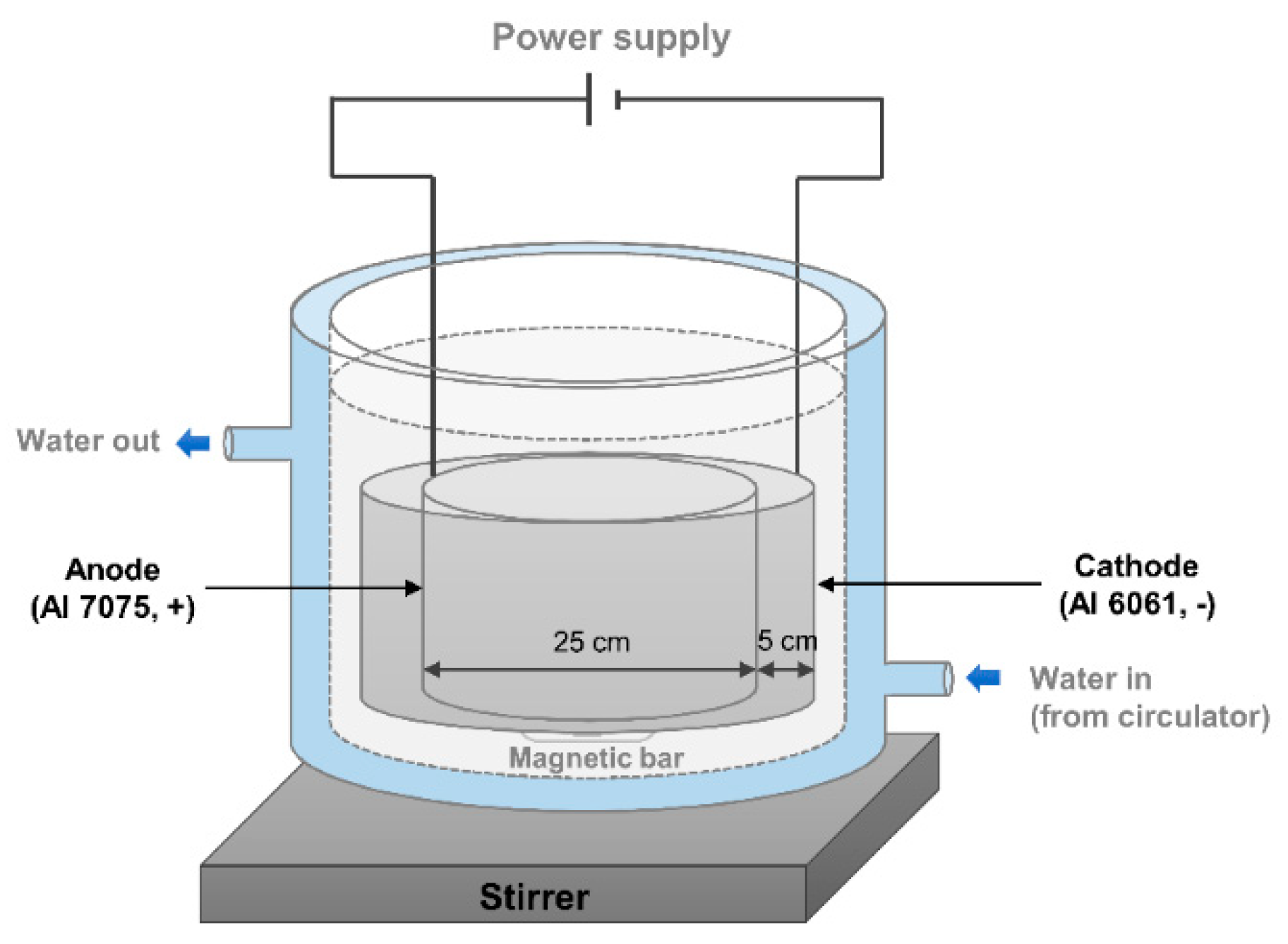
2.2. Preparation of the AAO Surface

Not only a plate shape but also a cylindrical shape were prepared for the experiment in this study because the cylindrical shape is frequently used in the subsea industry as housing for an electronic device. The AAO devices for the plate and cylindrical shapes are shown in Figure 1 and Figure 2, respectively. The following describes the details of the AAO preparation for both shapes.

2.2.1. Plate shape

All the samples were first rinsed with ethanol and isopropyl alcohol, and then they were cleaned using deionized water in a sonicator for 5 min. The anode was aluminum 7075, and the cathode was aluminum 6061. The distance between the anode and the cathode was fixed at approximately 5 cm as shown in Figure 1. A DC power supply (DRP-92305DU power supply) provided a constant voltage of 40 V, and the temperature was maintained by a circulator (Lab. Companion. RW-0525G) at 25 °C. The solution was 0.3 M oxalic acid solution, and it was stirred by a magnetic bar at a constant speed. The anodization was conducted for 3 h to generate 15 μm pore depth. After the anodizing, widening was conducted for 1 h under the same condition with anodizing to enlarge the pore diameter. The next step was oil impregnation. Oil (rust preventive oil, NP-7) was deposited on the nanoporous structure. The oil used in this study was a lubricant, which mostly consists of paraffin.

2.2.2. Cylindrical shape

The cylindrical shape’s anode was installed as shown in Figure 2 and the cylindrical shape’s cathode was also built for homogeneous anodizing. First, the samples were rinsed with ethanol and isopropyl alcohol. The anode was commercial aluminum 7075, and the cathode was aluminum 6061. The diameter of the cylindrical anode was 25 cm, and that of the cylindrical cathode was 35 cm. The distance between the anode and the cathode was adjusted to be about 5 cm. A DC power supply (PNCYS. EP-10010) provided a constant voltage of 40 V, and the temperature was maintained by a circulator (Lab. Companion. RW-0525G) at 25 °C. The anodizing time was 3 h, and the solution was 0.3 M oxalic acid solution—the same condition as the anodizing condition of the plate shape. Finally, the oil was impregnated on the surface of the AAO.

2.3. Salt Spray Test
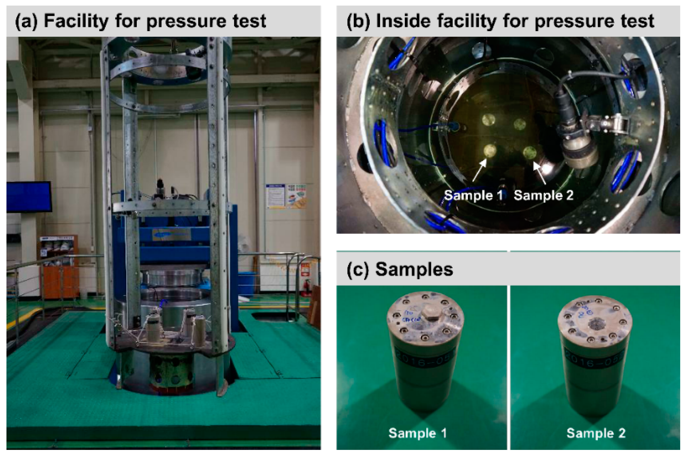
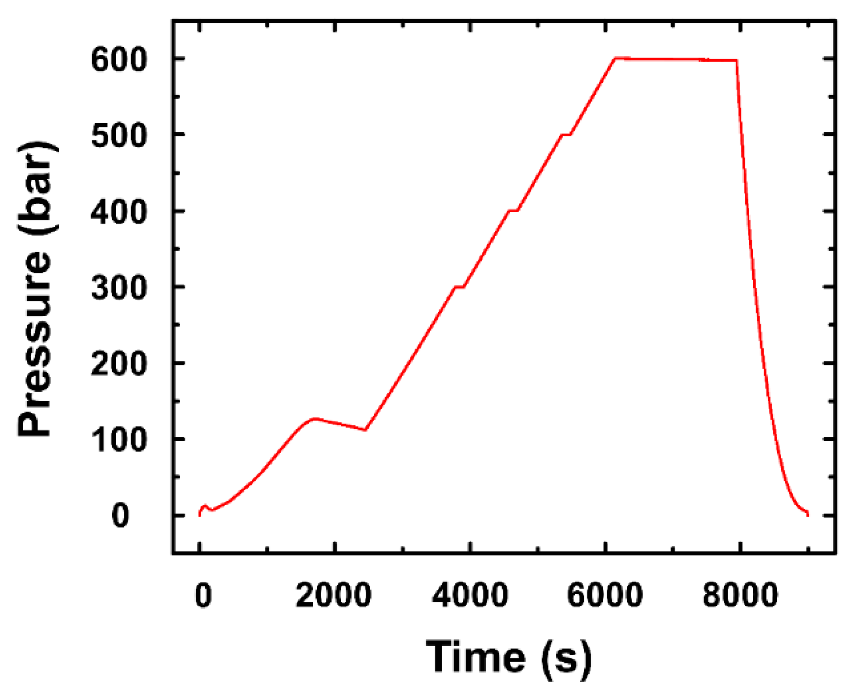
The salt spray test was performed to investigate the corrosion effect on the surface directly. The (bare) aluminum and the oil impregnated AAO surfaces of aluminum 7075 were analyzed for comparison. This salt spray test complies with ‘Standard: KSA–KS D 9502′. This standard contains a salt spray test for the anodic oxidation of metallic materials and various coatings. It conforms with ISO 9227:2006 (Corrosion tests in artificial atmospheres—salt spray tests). A 5% concentration of brine was utilized for the salt spray test, and the temperature of the test was maintained at 35 °C. The test was performed for 720 h for the oil impregnated AAO surface of aluminum 7075.

2.4. Pressure Test

This study carried out a pressure test to investigate the surface of the oil impregnated AAO of aluminum 7075 under high-pressure conditions. As the subsea equipment is installed in the seabed, it is exposed to the high-pressure environment—when going down 10 m below sea level, the pressure increases by approximately 1 bar. Since the surface of the oil impregnated AAO can be damaged under the high-pressure condition, a pressure test was required. Figure 3a,b shows the facility for the high-pressure test, which complies with ‘MIL-STD-810G’ (Department of defense test method standard, part two-laboratory test methods, 512.5 Immersion) and ‘ABS NOTICE’ (Rules for building and classing underwater vehicles, systems and hyperbaric facilities, Section 3 general requirement and safeguards, 3 proof testing, 3.1 hydrostatic test). Two cylindrical samples, which had 80 mm (diameter) × 150 mm (length), were prepared (Figure 3c). The pressure of the facility was gradually increased to 600 bar for 6000 s as shown in Figure 4. The samples were examined at 600 bar for 1800 s.

2.5. Measurement

The contact angle of a water droplet on the surface was measured to analyze the corrosion resistance by the wettability. The water droplets were placed on the surface by a microsyringe and then the measurement of the contact angle was conducted for each sample at least five times. The mean value was used as the result value. Low contact angle (high wettability) means that a water droplet is spread over a relatively wide area of the surface. It can be easily attacked by corrosion due to its large interaction area. In contrast, a water droplet having a high contact angle interacts with a small region on the surface (low wettability). Field Emission Scanning Electron Microscope (FE-SEM, JSM-7100F) was utilized for SEM images.

3. Results and Discussion

3.1. Plate Shape

3.1.1. FE-SEM Image of Plate Shape

Figure 5 shows the FE-SEM images of AAO and AAO with 1-h widening. Before widening, the pore diameter was about 35 nm, and the pore depth approximately 15 μm. The uniform surface is shown in the microscale image (Figure 5a), and the nanoporous structure is indicated in the nanoscale image (Figure 5b). After 1 h widening, a crack was generated in the microscale image (Figure 5c) and the nanoporous structure was collapsed in the nanoscale image (Figure 5d). The widening process was not considered in this study due to the collapse of the nanoporous structure.

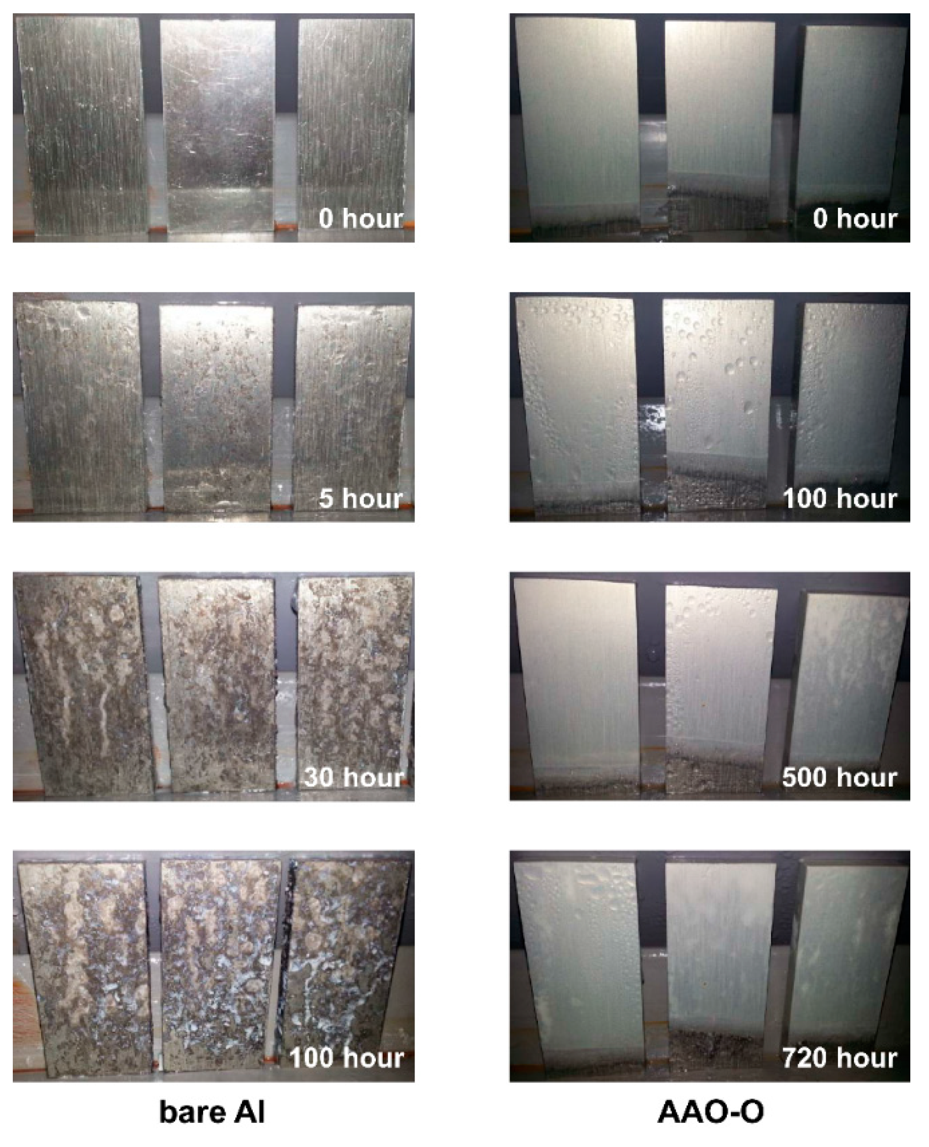
3.1.2. Salt Spray Test

Figure 6 shows the results of the salt spray test for bare aluminum and AAO-O (oil impregnation on anodic aluminum oxide) surfaces of aluminum 7075. Corrosion was indicated after 5 h in the case of bare aluminum, whereas the corrosion was not generated in the case of the AAO-O after 720 h. The salt spray test was stopped after 100 h in the bare aluminum case as the corrosion was intensively examined after 100 h. In the case of AAO-O, the test was continuously conducted up to 720 h. The results of the salt spray test showed that the oil impregnation on the AAO surface of aluminum 7075 could enhance the corrosion resistance.

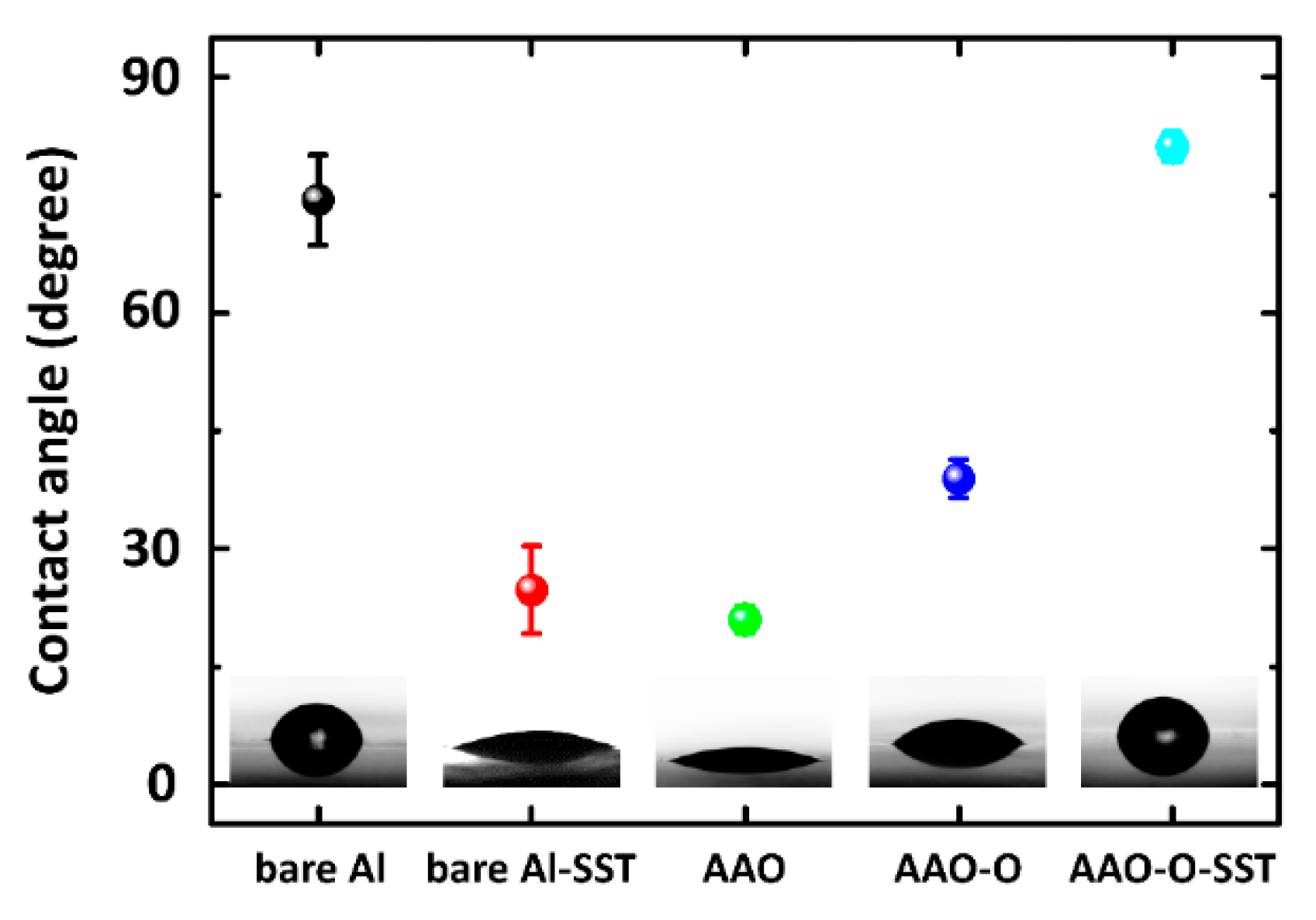
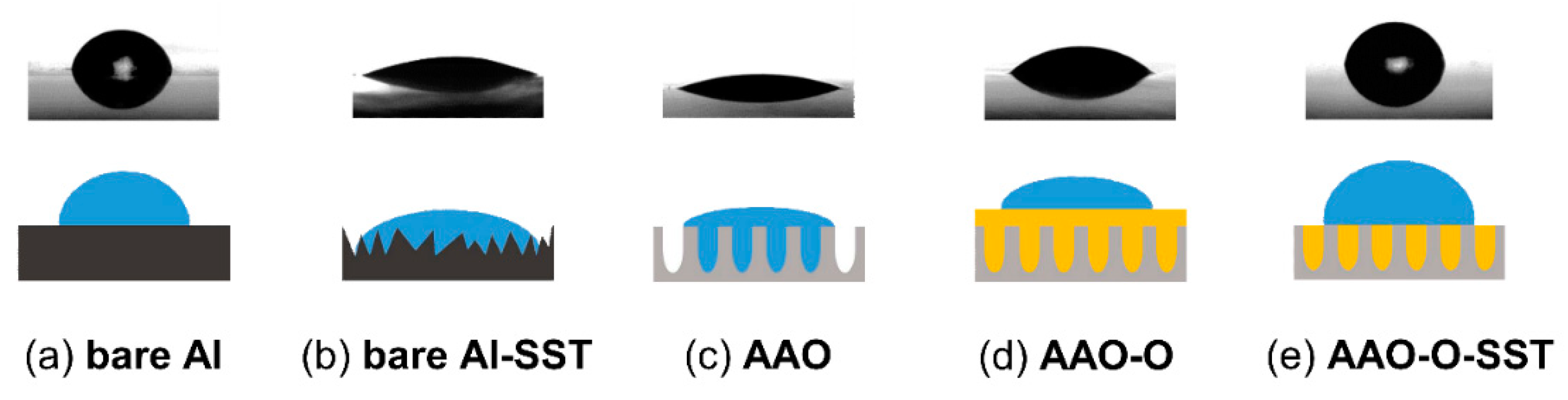
3.1.3. Contact Angle of Plate Shape

Figure 7 indicates the contact angles of AAO, AAO-O (oil impregnation), and AAO-O-SST (salt spray test). The contact angles of bare aluminum and bare aluminum-SST (salt spray test) were also investigated for comparison. The contact angle of a water droplet on the bare aluminum was 74.4° ± 5.8°, and it was significantly decreased to 24.8° ± 5.6° after the salt spray test. The bare aluminum is susceptible to corrosion. After anodizing, the contact angle was dropped to 21.0° ± 1.7°. It showed that the nanoporous structure enhanced the wettability of water by increasing surface roughness. After oil impregnation on the AAO surface, the contact angle was increased. The contact angle of a water droplet on AAO-O-SST was 81.1° ± 1.9°. Although the salt spray test was conducted on the oil-impregnated AAO surface, the contact angle of the water droplet on AAO-O-SST was significantly increased.
Figure 8 presents the schematic cross-section diagram of bare aluminum, bare aluminum-SST (salt spray test), AAO, AAO-O (oil impregnation), AAO-O-SST (salt spray test) surfaces. Bare aluminum indicated a relatively flat surface, whereas the roughness was considerably increased after the salt spray test as shown in Figure 6. The results of the contact angle test showed that the contact angle of bare Al was decreased after the salt spray test. A surface of high roughness generally presents a low contact angle. Oxidized aluminum by the salt spray test increased the roughness of the surface, and the increased roughness reduced the contact angle. After anodizing, a nanoporous structure was generated. The produced nanoporous structure by anodizing decreased the contact angle. After oil impregnation on the AAO surface, the contact angle was increased. We assumed that the oil entirely covered the surface of the AAO. The contact angle on the surface of the AAO-O-SST was significantly increased after the salt spray test. It could be imagined that some oil remained on the nanoporous structure after the salt spray test as shown in Figure 8e. If there was no oil remaining on the surface of the AAO-O-SST, the contact angle would be similar to the contact angle of the AAO. When the oil layer was completely covered on the top of the surface of the AAO-O-SST, the contact angle would be similar to the contact angle of the AAO-O. The contact angle of the AAO-O-SST had a similar contact angle to the bare aluminum because the exposed nanoporous structure held the droplet.
This study analyzed the interfacial tension between the proposed surfaces and water. The interfacial tension shows the adhesive force between the liquid phase of one substance and the liquid, solid or gas state of another element. When there is high interfacial tension, the water spreads on the surface. The high interfacial tension indicates a hydrophilic surface, whereas little interfacial tension shows a hydrophobic surface. Therefore, the high interfacial tension poses a low contact angle, and the low interfacial tension has a high contact angle. The interfacial tension was calculated by proposed equations from previous studies.
We employed the formulas in the Smith et al. study [30] to calculate the interfacial tension between the water and the proposed surfaces. The formula for the interfacial tension between the aluminum surfaces and the water is indicated in Equation (1). The formula for the interfacial tension between the AAO surfaces and the water is shown in Equation (2). Equation (3) shows the formula for the interfacial tension between the AAO-O-SST surfaces and the water. Since we assumed that the oil on the surface of the AAO-O-SST was thoroughly infused, the interfacial tension between the aluminum and the oil was not taken into account.
γ s w = σ s + σ w 2 σ s σ w
γ A w = r γ s w
γ A S w = f γ s w + ( 1 f ) γ o w
where γsw is interfacial tension between the solid (aluminum) and the liquid (water), γow is that between the oil and the water, γAw is that between the AAO surfaces and the water, and γASw is that between the AAO-O-SST surfaces and the water. σs is the surface free energy of the solid, and σw is the surface tension of the liquid. r is the roughness factor which is the ratio of the total surface area to the projected area of the solid in contact with liquid, and f is the fraction of the projected area of the surface that is occupied by the solid.
The roughness factor (r) was calculated by Equation (4).
r = 1 + 2 π a 2 h ( a + b ) 2
where a, b, and h are the pore diameter, edge-to-edge spacing, and the height, respectively. a and b were 30 and 70 nm, and h was 15 μm. f is predicted to be 0.65 using the FE-SEM image of the AAO surface.
There are various models to predict the interfacial tension between different substances and phases: Owens–Wendt–Rabel–Kaelble (OWRK), Wu, Oss and Good (acid-base), Fowkes, and Extended Fowkes [36,37]. This study employed the Fowkes model. Although the Extended Fowkes model furthermore consideres polar interactions and a hydrogen bonding fraction as shown in Equation (5), those two fractions are insignificant in these cases. The surface tension of water, aluminum, and oil are 72.8, 45.0, and 25.0 mN/m, respectively. The dispersion contribution of water is 21.8 mN/m.
γ α β = σ α + σ β 2 ( σ α D σ β D + σ α P σ β P + σ α H σ β H )
where α is aluminum or oil, and β is water. σD is the dispersion force contribution, and σP is the polar interaction. σH indicates the hydrogen bonding fraction.
The diagrams of the proposed surfaces and the interfacial tensions are tabulated in Table 1. The interfacial tension of bare aluminum and AAO-O-SST showed relatively low values, whereas that for AAO noted a considerably high value. As indicated before, the surfaces of aluminum and AAO-O-SST had a relatively high contact angle. Since the high contact angle means low interfacial tension, the calculated results of interfacial tension agreed with the results of the contact angle. The interfacial tension of the AAO-O-SST was slightly less in value than that of bare aluminum, and the contact angle of the AAO-O-SST was slightly higher than that of bare aluminum. The interfacial tensions at AAO had a significantly high value due to the high roughness factor. The deep pore depth caused the high roughness factors.

3.2. Cylindrical Shape

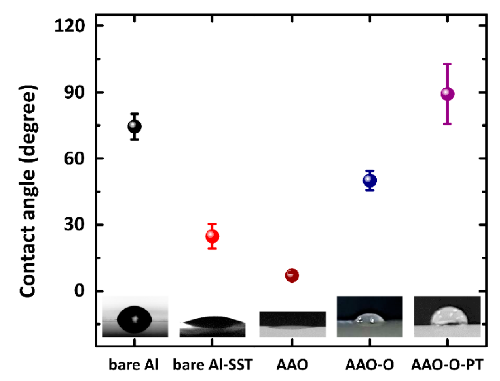
Contact Angle of Cylindrical Shape

Figure 9 indicates the contact angles of AAO, AAO-O, and AAO-O-PT (pressure test) for the cylindrical shape of aluminum 7075. After anodizing, the contact angle was decreased. After oil impregnation, the contact angle was increased to 50.0° ± 4.4° like that in the plate shape. The contact angle of the AAO-O-PT was approximately 89.1° ± 13.6°. Although the pressure test was conducted on AAO-O, the contact angle was increased by 39.1°. This result showed that some oil remained in the nanoporous structure, even though the oil on the top of the nanoporous structure was removed. The combination of the nanoporous structure and the oil in the pores caught the water droplet. Therefore, the high contact angle was investigated in the case of oil impregnation.

3.3. Comparison of Plate with Cylindrical Shapes

The cylindrical shape indicated a similar tendency to the plate shape. Although the contact angle of AAO was low in both shapes, they were increased by the oil impregnation. The salt spray test and the pressure test eliminated the covered oil on the top of the nanoporous structure, but could not remove the oil in the pores. The combination of the exposed nanoporous structures and the oil filled in the pores increased the contact angle significantly. These results showed that the oil impregnation on the AAO surface of aluminum 7075 in both shapes increased the corrosion resistance.

4. Conclusions

This study analyzed the corrosion resistance of the oil impregnated AAO surface of aluminum 7075 to suggest a way to improve the corrosion protection for subsea application. The cylindrical shape was investigated as well as the plate shape. The contact angle was measured, and the interfacial tension between the water and the surfaces were calculated using the proposed equations. The salt spray test was conducted in the case of the plate shape, whereas the pressure test was carried out in the case of the cylindrical shape. Although salt spray and pressure tests were conducted, the oil in the pores of the AAO surface remained. The contact angle of the oil impregnated AAO surface was increased after the salt spray and pressure tests. That is, the nanoporous structure and the remaining oil in the pores help to maintain a high contact angle. The calculated interfacial tension coincided with the measurement of the contact angle. Corrosion was not indicated in the oil impregnated AAO surface for the 720 h salt spray test. The impregnated oil in the pores can endure a high-pressure condition (600 bar). Enhanced aluminum 7075 by AAO and oil impregnation can be used for subsea equipment.

Author Contributions

Conceptualization, J.-Y.J.; Methodology, J.C.; Validation, S.L.; Formal Analysis, Y.S.; Writing—Original Draft Preparation, Y.S.; Writing—Review & Editing, J.-Y.J.

Funding

This research was supported by a grant from the Endowment Project of “Development of the Surface Modification Technologies based on Metal-Oxide for Offshore Equipment” (PES9320) and “Development of Technology to Support the Rapid Search and Rescue of Marine Accidents” (PES3130) funded by Korea Research Institute of Ships and Ocean Engineering.

Conflicts of Interest

The authors declare no conflict of interest.

References

  1. Wu, L.K.; Liu, L.; Li, J.; Hu, J.M.; Zhang, J.Q.; Cao, C.N. Electrodeposition of cerium (III)-modified bis-[triethoxysilypropyl]tetra-sulphide films on AA2024-T3 (aluminum alloy) for corrosion protection. Surf. Coat. Technol. 2010, 204, 3920–3926. [Google Scholar] [CrossRef]
  2. Hu, J.M.; Liu, L.; Zhang, J.Q.; Cao, C.N. Electrodeposition of silane films on aluminum alloys for corrosion protection. Prog. Org. Coat. 2007, 58, 265–271. [Google Scholar] [CrossRef]
  3. Simões, A.M.; Battocchi, D.; Tallman, D.E.; Bierwagen, G.P. SVET and SECM imaging of cathodic protection of aluminium by a Mg-rich coating. Corros. Sci. 2007, 49, 3838–3849. [Google Scholar] [CrossRef]
  4. Grundmeier, G.; Schmidt, W.; Stratmann, M. Corrosion protection by organic coatings: Electrochemical mechanism and novel methods of investigation. Electrochim. Acta 2000, 45, 2515–2533. [Google Scholar] [CrossRef]
  5. Cohen, S.M. Review: Replacements for Chromium Pretreatments on Aluminum. Corrosion 1995, 51, 71–78. [Google Scholar] [CrossRef]
  6. Diggle, J.W.; Downie, T.C.; Goulding, C.W. Anodic oxide films on aluminum. Chem. Rev. 1969, 3, 365–405. [Google Scholar] [CrossRef]
  7. Masuda, H.; Fukuda, K. Ordered metal nanohole arrays made by a two-step replication of honeycomb structures of anodic alumina. Science 1995, 268, 1466–1468. [Google Scholar] [CrossRef]
  8. Masuda, H.; Satoh, M. Fabrication of gold nanodot array using anodic porous alumina as an evaporation mask. Jpn. J. Appl. Phys. Part 2 Lett. 1996, 35. [Google Scholar] [CrossRef]
  9. Masuda, H.; Yada, K.; Osaka, A. Self-Ordering of Cell Configuration of Anodic Porous Alumina with Large-Size Pores in Phosphoric Acid Solution Self-Ordering of Cell Configuration of Anodic Porous Alumina with Large-Size Pores in Phosphoric Acid Solution. Jpn. J. Appl. Phys. 1998, 1340, 9–12. [Google Scholar] [CrossRef]
  10. Li, A.P.; Müller, F.; Birner, A.; Nielsch, K.; Gösele, U. Hexagonal pore arrays with a 50–420 nm interpore distance formed by self-organization in anodic alumina. J. Appl. Phys. 1998, 84, 6023–6026. [Google Scholar] [CrossRef]
  11. Schwirn, K.; Lee, W.; Hillebrand, R.; Steinhart, M.; Nielsch, K.; Gösele, U. Self-Ordered Anodic Aluminum Oxide Formed by H2SO4Hard Anodization. ACS Nano 2008, 2, 302–310. [Google Scholar] [CrossRef]
  12. Zhang, J.; Kielbasa, J.E.; Carroll, D.L. Controllable fabrication of porous alumina templates for nanostructures synthesis. Mater. Chem. Phys. 2010, 122, 295–300. [Google Scholar] [CrossRef]
  13. Hwang, S.; Jeong, S.; Hwang, H.; Lee, O.; Lee, K. Fabrication of Highly Ordered Pore Array in Anodic Aluminum Oxide. Korean J. Chem. Eng. 2002, 19, 467–473. [Google Scholar] [CrossRef]
  14. Lee, K.; Lyu, S.; Lee, S.; Kim, Y.S.; Hwang, W. Characteristics and self-cleaning effect of the transparent super-hydrophobic film having nanofibers array structures. Appl. Surf. Sci. 2010, 256, 6729–6735. [Google Scholar] [CrossRef]
  15. Nelson, S.F.; Lin, Y.Y.; Gundlach, D.J.; Jackson, T.N. Temperature-independent transport in high-mobility pentacene transistors. Appl. Phys. Lett. 1998, 72, 1854–1856. [Google Scholar] [CrossRef]
  16. Whitney, T.M.; Searson, P.C.; Jiang, J.S.; Chien, C.L. Fabrication and magnetic properties of arrays of metallic nanowires. Science 1993, 261, 1316–1319. [Google Scholar] [CrossRef]
  17. Choi, D.H.; Lee, P.S.; Hwang, W.; Lee, K.H.; Park, H.C. Measurement of the pore sizes for anodic aluminum oxide (AAO). Curr. Appl. Phys. 2006, 6, 125–129. [Google Scholar] [CrossRef]
  18. Lee, J.; Jung, U.; Kim, W.; Chung, W. Effects of residual water in the pores of aluminum anodic oxide layers prior to sealing on corrosion resistance. Appl. Surf. Sci. 2013, 283, 941–946. [Google Scholar] [CrossRef]
  19. Huang, Y.; Shih, H.; Huang, H.; Daugherty, J.; Wu, S.; Ramanathan, S.; Chang, C.; Mansfeld, F. Evaluation of the corrosion resistance of anodized aluminum 6061 using electrochemical impedance spectroscopy (EIS). Corros. Sci. 2008, 50, 3569–3575. [Google Scholar] [CrossRef]
  20. Moutarlier, V.; Gigandet, M.P.; Normand, B.; Pagetti, J. EIS characterisation of anodic films formed on 2024 aluminium alloy, in sulphuric acid containing molybdate or permanganate species. Corros. Sci. 2005, 47, 937–951. [Google Scholar] [CrossRef]
  21. Zuo, Y.; Zhao, P.H.; Mao, J.M. The influences of sealing methods on corrosion behavior of anodized aluminum alloys in NaCl solutions. Surf. Coati. Technol. 2003, 166, 237–242. [Google Scholar] [CrossRef]
  22. González, J.A.; López, V.; Otero, E.; Bautista, A. Postsealing changes in porous aluminum oxide films obtained in sulfuric acid solutions. J. Electrochem. Soc. 2000, 147, 984–990. [Google Scholar] [CrossRef]
  23. Lu, Z.; Wang, P.; Zhang, D. Super-hydrophobic film fabricated on aluminium surface as a barrier to atmospheric corrosion in a marine environment. Corros. Sci. 2015, 91, 287–296. [Google Scholar] [CrossRef]
  24. Jeong, C.; Lee, J.; Sheppard, K.; Choi, C.H. Air-Impregnated Nanoporous Anodic Aluminum Oxide Layers for Enhancing the Corrosion Resistance of Aluminum. Langmuir 2015, 31, 11040–11050. [Google Scholar] [CrossRef]
  25. Wang, P.; Zhang, D.; Qiu, R.; Wan, Y.; Wu, J. Green approach to fabrication of a super-hydrophobic film on copper and the consequent corrosion resistance. Corros. Sci. 2014, 80, 366–373. [Google Scholar] [CrossRef]
  26. Ishizaki, T.; Masuda, Y.; Sakamoto, M. Corrosion resistance and durability of superhydrophobic surface formed on magnesium alloy coated with nanostructured cerium oxide film and fluoroalkylsilane molecules in corrosive NaCl aqueous solution. Langmuir 2011, 27, 4780–4788. [Google Scholar] [CrossRef]
  27. Liu, T.; Chen, S.; Cheng, S.; Tian, J.; Chang, X.; Yin, Y. Corrosion behavior of super-hydrophobic surface on copper in seawater. Electrochim. Acta 2007, 52, 8003–8007. [Google Scholar] [CrossRef]
  28. Lee, J.; Shin, S.; Jiang, Y.; Jeong, C.; Stone, H.A. Oil-Impregnated Nanoporous Oxide Layer for Corrosion Protection with Self-Healing. Adv. Funct. Mater. 2017, 27, 1606040. [Google Scholar] [CrossRef]
  29. Rykaczewski, K.; Anand, S.; Subramanyam, S.B.; Varanasi, K.K. Cryo-FIB/SEM Investigation of Mechanism of Frost Formation on Lubricant- Impregnated Surfaces. Microsc. Microanal. 2013, 19, 926–927. [Google Scholar] [CrossRef]
  30. Smith, J.D.; Dhiman, R.; Anand, S.; Reza-Garduno, E.; Cohen, R.E.; McKinley, G.H.; Varanasi, K.K. Droplet mobility on lubricant-impregnated surfaces. Soft Matter 2013, 9, 1772–1780. [Google Scholar] [CrossRef]
  31. Wang, P.; Zhang, D.; Lu, Z.; Sun, S. Fabrication of Slippery Lubricant-Infused Porous Surface for Inhibition of Microbially Influenced Corrosion. ACS Appl. Mater. Interfaces 2016, 8, 1120–1127. [Google Scholar] [CrossRef]
  32. Wang, P.; Lu, Z.; Zhang, D. Slippery liquid-infused porous surfaces fabricated on aluminum as a barrier to corrosion induced by sulfate reducing bacteria. Corros. Sci. 2015, 93, 159–166. [Google Scholar] [CrossRef]
  33. Song, T.; Liu, Q.; Liu, J.; Yang, W.; Chen, R.; Jing, X.; Takahashi, K.; Wang, J. Fabrication of super slippery sheet-layered and porous anodic aluminium oxide surfaces and its anticorrosion property. Appl. Surf. Sci. 2015, 355, 495–501. [Google Scholar] [CrossRef]
  34. Yang, S.; Qiu, R.; Song, H.; Wang, P.; Shi, Z.; Wang, Y. Slippery liquid-infused porous surface based on perfluorinated lubricant/iron tetradecanoate: Preparation and corrosion protection application. Appl. Surf. Sci. 2015, 328, 491–500. [Google Scholar] [CrossRef]
  35. Jacobi, I.; Wexler, J.S.; Stone, H.A. Overflow cascades in liquid-infused substrates. Phys. Fluids 2015, 27. [Google Scholar] [CrossRef]
  36. Shaw, D.J. Chapter 4 Liquid-gas and liquid-liquid interfaces In Introduction to Colloid and Surface Chemistry, 2nd ed.; CRC Press: Burlington, VT, USA, 1980; pp. 64–114. [Google Scholar]
  37. Surface Free Energy (SFE), Surface Energy. Available online: https://www.kruss-scientific.com/services/education-theory/glossary/surface-free-energy/ (accessed on 27 August 2019).
Figure 1. Anodic aluminum oxide device for the plate shape.
Applsci 09 03762 g001
Figure 2. Anodic aluminum oxide device for the cylindrical shape.
Applsci 09 03762 g002
Figure 3. Facility for pressure test and samples.
Applsci 09 03762 g003
Figure 4. Pressure with time in pressure test facility.
Applsci 09 03762 g004
Figure 5. FE-SEM images of anodic aluminum oxide with widening of aluminum 7075.
Applsci 09 03762 g005
Figure 6. Results of salt spray test for bare aluminum and AAO-O (oil impregnation on anodic aluminum oxide) surfaces.
Applsci 09 03762 g006
Figure 7. Contact angles of bare aluminum, bare aluminum-SST (salt spray test), AAO (anodic aluminum oxide), AAO-O (oil impregnation), and AAO-O-SST (salt spray test) surfaces of aluminum 7075.
Applsci 09 03762 g007
Figure 8. Schematic cross-section diagram of bare aluminum, bare aluminum-SST (salt spray test), AAO (anodic aluminum oxide), AAO-O (oil impregnation), AAO-O-SST (salt spray test) surfaces.
Applsci 09 03762 g008
Figure 9. Contact angles of AAO (anodic aluminum oxide), AAO-O (oil impregnation), and AAO-O-PT (pressure test) surfaces for cylindrical shape of aluminum 7075.
Applsci 09 03762 g009
Table 1. Interfacial tensions between water and bare aluminum, AAO (anodic aluminum oxide), and AAO-O-SST (oil impregnation—salt spray test).
Bare AluminumAAOAAO-O-SST
Diagram Applsci 09 03762 i001 Applsci 09 03762 i002 Applsci 09 03762 i003
Interfacial tension (mN/m)55.27853.053.7

