The Dynamic Characteristic of a Faulted Rotor System with Multi-Objective Optimization Designed SFD


Abstract
:1. Introduction
2. The Basic Theory
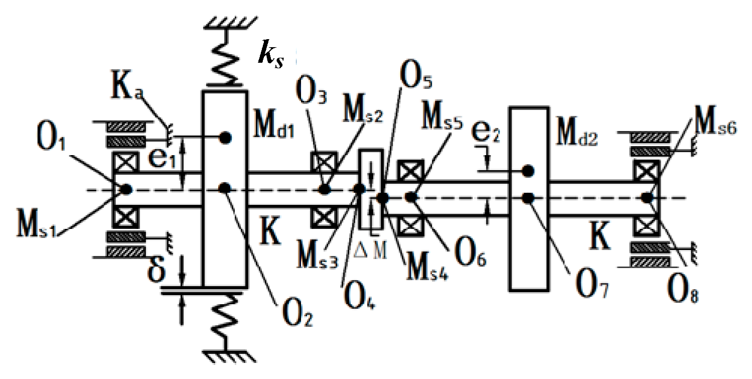
2.1. Rotor System
2.2. Rub-Impact Model
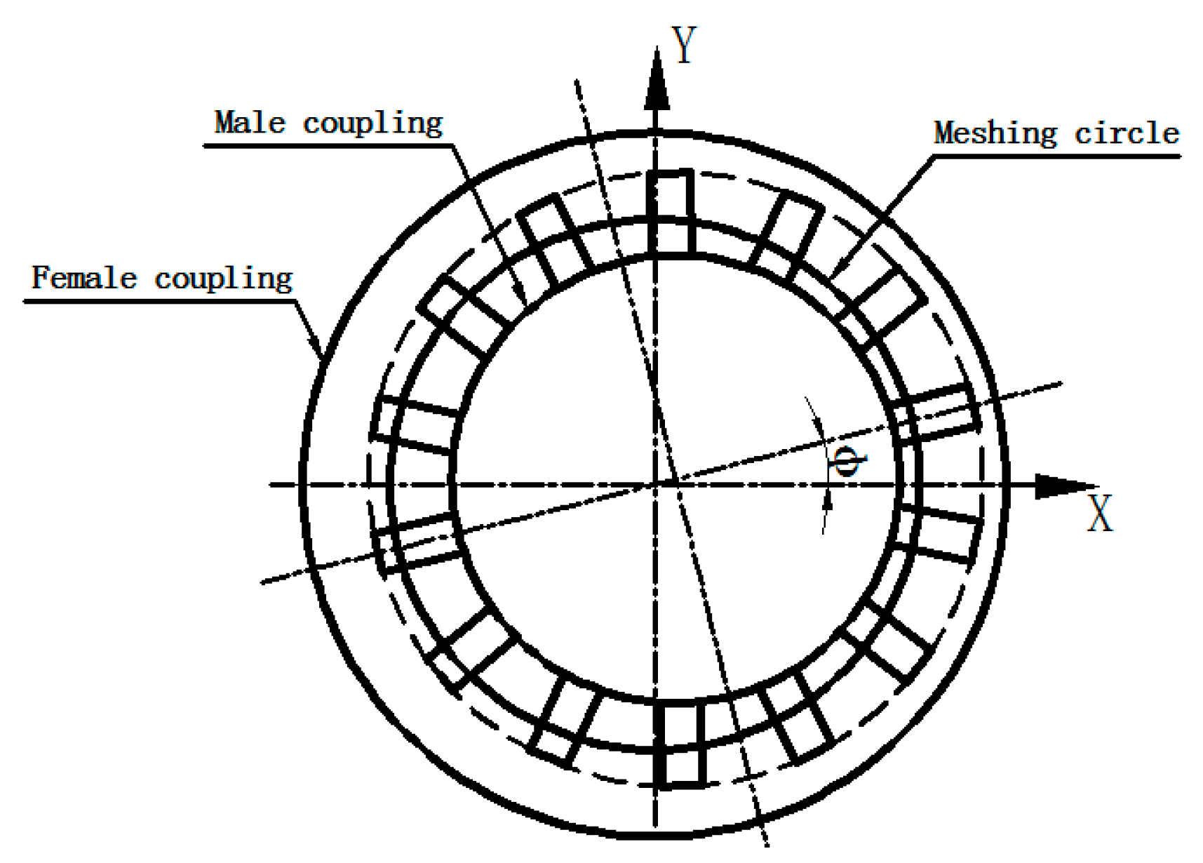
2.3. Gear Coupling Model
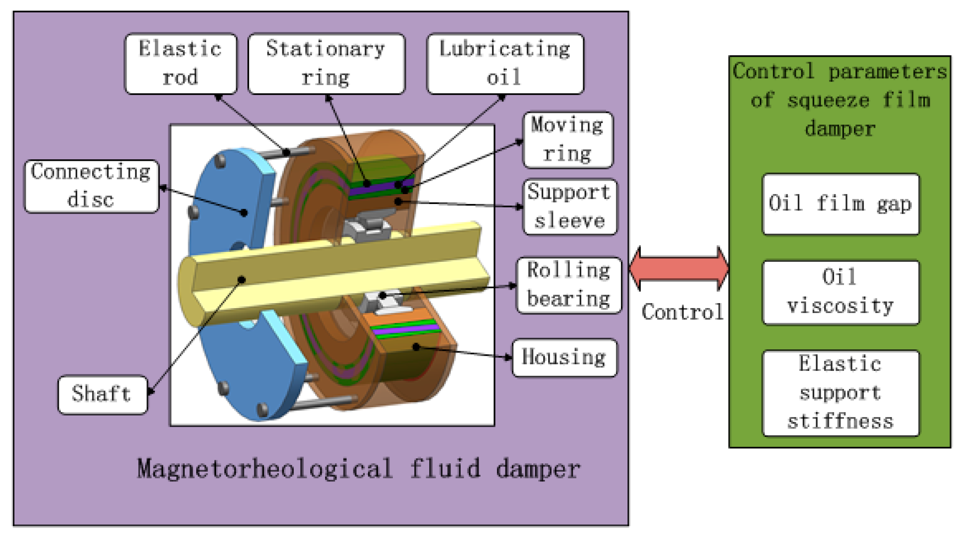
2.4. Squeeze Film Damper
2.5. Rolling Bearing Force Model
2.6. The Optimal Latin Hyercube Design
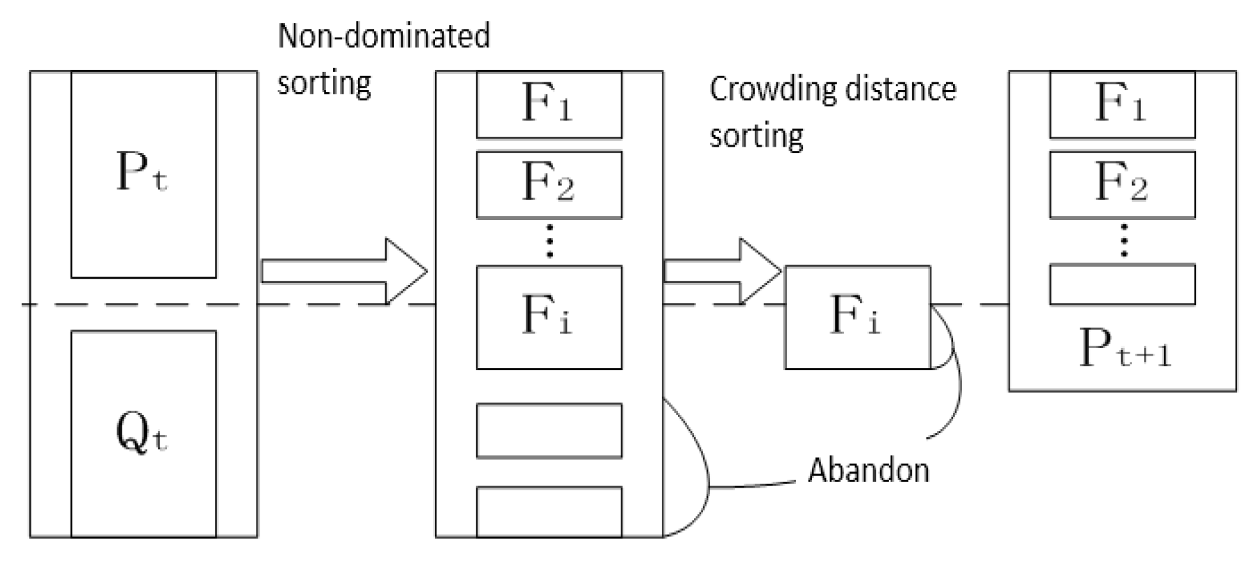
2.7. Non-Dominated Sorting Genetic Algorithm with Elite Strategy (NSGA-II)
3. Multi Objective Optimization of SFD Parameters
3.1. Initial Scheme and Experimental Design of SFD
3.2. Single Objective Parameter Optimization Analysis of the Normal Rotor System
3.3. Analysis Results of Optimization Parameters of Rotor System with the Misalignment Fault
3.4. Analysis Results of Optimization Parameters of Rotor System with the Misalignment-Rubbing Coupling Fault
3.5. Comparison Results of SFD Parameters of the Rotor System under Three Conditions
4. Conclusions
- (1)
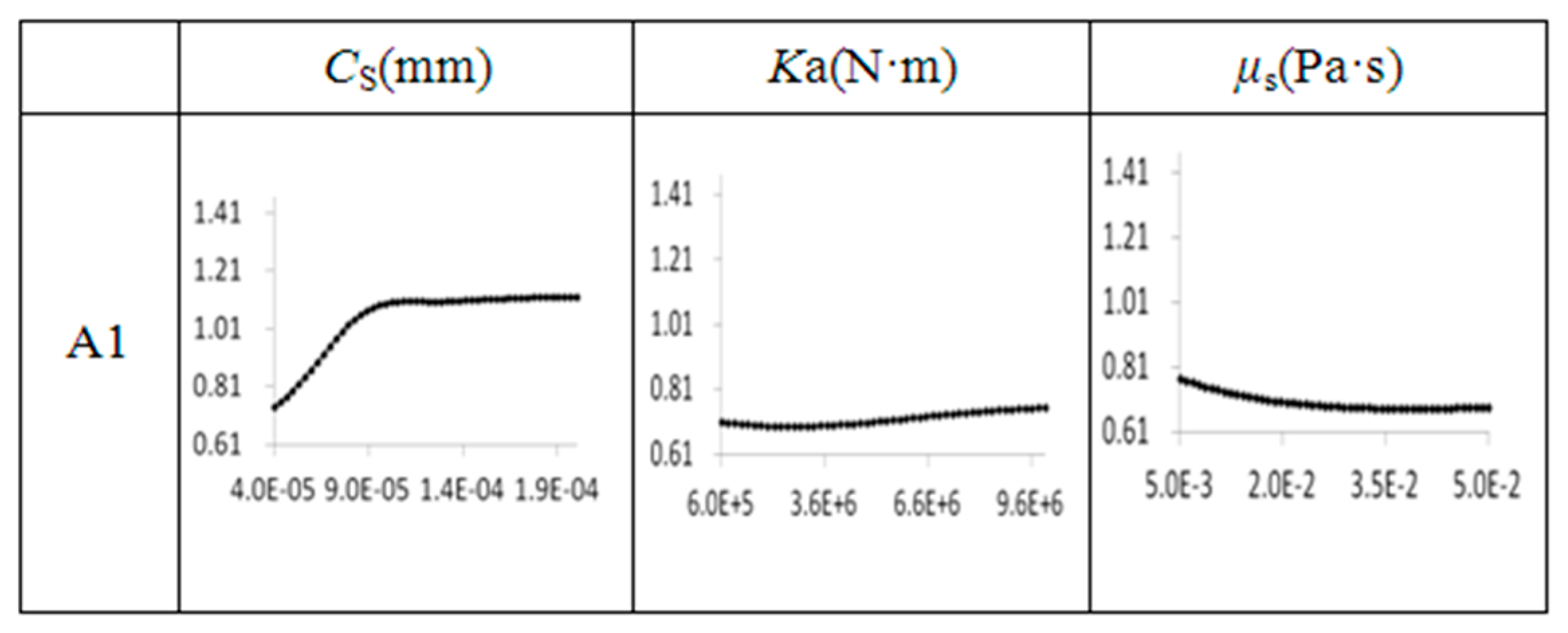
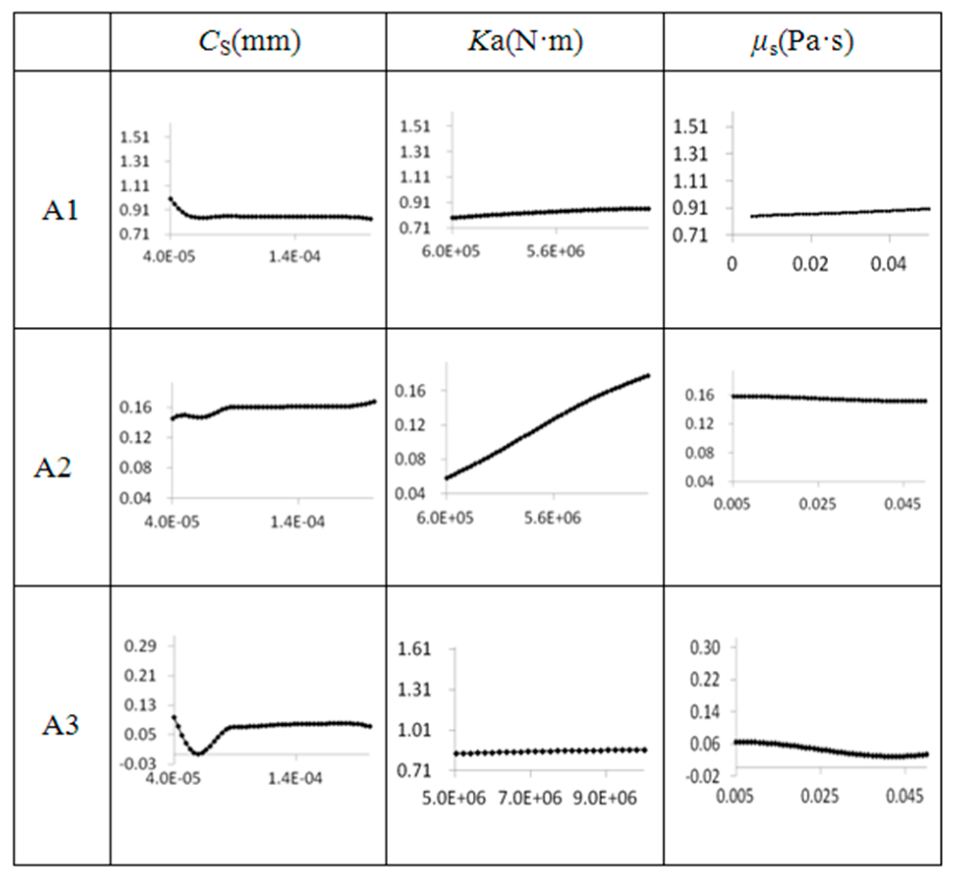
- For the vibration responses caused by the system with misalignment fault, three variable parameters are strongly nonlinear, in which Ka has obvious impact on fundamental, 2× fundamental and 3× fundamental frequency, CS and μs are weak., For the vibration responses caused by a misalignment-rubbing coupling faults system, in which CS has a remarkable effect on fundamental frequency, μs and Ka are sensitive to 2× fundamental and 3× fundamental frequency, respectively.
- (2)
- Optimizing the parameters of SFD have an effect on vibration control and stability of the rotor system with varied faults by using NLPQL and NSGA-II algorithm. The vibration responses of the system with the optimization parameters are shown as: With no fault, the amplitude of fundamental frequency decreased by 23%. With the misalignment fault, the amplitude of the fundamental frequency decreased by 43.4%, the amplitude of 2× fundamental frequency decreased by 27.5%, while the amplitude of 3× fundamental frequency decreased by 66.7%. With the misalignment-rubbing coupling fault, the amplitude of fundamental frequency decreased by 7.4%, the amplitude of 2× fundamental frequency decreased by 51.5%, and the amplitude of 3× fundamental frequency decreased by 16.8%. Overall, the feasibility of the optimization method of the variable-structured SFD operational parameters for the faulted rotor system was verified.
- (3)
- The research results presented in the paper can provide helpful guidance for the design of the SFD and will be validated by experiments in the next planned step.
Author Contributions
Funding
Conflicts of Interest
Appendix A

| Parameters | Values |
|---|---|
| Ms1 = Ms2 = Ms3 = Ms4 = Ms5 = Ms6 (kg) | 1 |
| Md1, Md2 (kg) | 15, 12 |
| K (N/m) | 2.5 × 10⁷ |
| e1, e2 (m) | 1 × 10⁻⁵, 5 × 10⁻⁶ |
| Cz, Cp (N·s/m) | 2100, 1500 |
| Parameters | Values |
|---|---|
| Rs, L (m) | 0.03, 0.011 |
| Parameters | Values |
|---|---|
| n | 7 |
| Cb (N/m1.5) | 5 × 10⁹ |
| (m) | 3 × 10⁻⁶ |
| Parameters | Values |
|---|---|
| ks (N/m) | 5 × 10⁷ |
| δ (m) | 1 × 10⁻⁵ |
| f | 0.1 |
| Parameters | Values |
|---|---|
| z | 14 |
| Li, R (m) | 3.07 × 10⁻³, 6.95 × 10⁻² |
| T (N m) | 1000 |
References
- Olove, B. Non-linear behavior of a flexible shaft. SFD 1997, 206, 255–260. [Google Scholar]
- Humes, B. The Non-Linear Performance of Squeeze Film Damper; University of Sussex: Brighton, UK, 1977. [Google Scholar]
- Copper, S. Preliminary investigation of oil film for the control of vibration. Mech. Eng. 1963, 5, 305–315. [Google Scholar]
- Ruggiero, A.; D’Amato, R.; Magliano, E.; Kozak, D. Dynamical simulations of a flexible rotor in cylindrical uncavitated and cavitated lubricated journal bearings. Lubricants 2018, 6, 40. [Google Scholar] [CrossRef]
- Wang, J.; Zhang, J.; Ma, L.; Yu, Y. Study on the Effect Mechanism of MRD to Rotor System. Appl. Sci. 2019, 9, 2247. [Google Scholar] [CrossRef]
- Chang-Jian, C.W. Non-linear dynamic analysis of a HSFD mounted gear-bearing system. Nonlinear Dyn. 2010, 62, 333–347. [Google Scholar] [CrossRef]
- Chang-Jian, C.W.; Kuo, J.K. Bifurcation and chaos for porous squeeze film damper mounted rotor–bearing system lubricated with micropolar fluid. Nonlinear Dyn. 2009, 58, 697–714. [Google Scholar] [CrossRef]
- Chang-Jian, C.W.; Yau, H.T.; Chen, J.L. Nonlinear dynamic analysis of a hybrid squeeze-film damper-mounted rigid rotor lubricated with couple stress fluid and active control. Appl. Math. Model. 2010, 34, 2493–2507. [Google Scholar] [CrossRef]
- Inayat-Hussain, J.I. Bifurcations of a flexible rotor response in squeeze-film dampers without centering springs. Solitons Fractals 2005, 24, 583–596. [Google Scholar] [CrossRef]
- Inayat-Hussain, J.I. Bifurcations in the response of a flexible rotor in squeeze-film dampers with retainer springs. Solitons Fractals 2009, 39, 519–532. [Google Scholar] [CrossRef]
- Qin, W.; Zhang, J.; Wang, H. Response and bifurcation of rotor with squeeze film damper supported on elastic foundation. J. Northwestern Polytech. Univ. 2006, 24, 245–248. [Google Scholar]
- Yuan, H.; Wang, Z.; Wen, B. Analysis on stability of dual-discs rub-impact rotor with consideration of casing elasticity. J. Vib. Shock. 2010, 29, 52–54. [Google Scholar]
- Zhao, G.; Liu, Z.; Ye, J. Dynamic behavior of a rotor-misaligned spline coupling system. J. Vib. Shock 2009, 28, 78–82. [Google Scholar]
- Wen, B.; Gu, J.; Xia, S. The Advanced Rotor Dynamics; China Machine Press: Beijing, China, 2000. [Google Scholar]
- Cheng, M.; Meng, G. Dynamic analysis of a rotor-ball bearing nonlinear system with Alford force. China Mech. Eng. 2011, 22, 2806–2812. [Google Scholar]
- Park, J.S. Optimal latin-hypercube designs for computer experiments. J. Stat. Plan. Inference 1994, 39, 95–111. [Google Scholar] [CrossRef]
- Lei, D.; Yan, X. Multi-Objective Intelligent Optimization Algorithm and Its Application; Science Press: Beijing, China, 2009. [Google Scholar]
- Li, X. Dynamic Analysis and Identification for Rotor Misalignment-Rubbing Coupling Faults; Nanjing University of Aeronautics and Astronautics: Nanjing, China, 2009. [Google Scholar]


| Design Parameters | Initial Value | The Changing Range/mm |
|---|---|---|
| CS (mm) | 8 × 10⁻⁵ | (4 × 10⁻⁵, 2 × 10⁻⁴) |
| Ka (N·m) | 3 × 10⁶ | (6 × 10⁵, 8 × 10⁷) |
| μs (Pa·s) | 0.02 | (0.005, 0.01) |
| Design Parameter | 1 | 2 | 3 | 80 |
|---|---|---|---|---|
| CS (mm) | 1.4 × 10⁻⁴ | 1.1 × 10⁻⁴ | 1.5 × 10⁻⁴ | 1.8 × 10⁻⁴ |
| Ka (N·m) | 6 × 10⁶ | 8.7 × 10⁶ | 3.9 × 10⁶ | 4.8 × 10⁶ |
| μs (Pa·s) | 4.8 × 10⁻² | 2.3 × 10⁻² | 2.7 × 10⁻² | 4.6 × 10⁻² |
| System Status | CS (mm) | Ka (N·m) | μs (Pa·s) |
|---|---|---|---|
| Before optimization | 8 × 10⁻⁵ | 3 × 10⁶ | 0.02 |
| No fault (after optimization) | 4 × 10⁻⁵ | 8 × 10⁶ | 0.038 |
| Misalignment faults (after optimization) | 2 × 10⁻⁴ | 6 × 10⁵ | 5 × 10⁻³ |
| Misalignment-rubbing coupling faults (after optimization) | 8 × 10⁻⁵ | 6 × 10⁵ | 5 × 10⁻² |
© 2019 by the authors. Licensee MDPI, Basel, Switzerland. This article is an open access article distributed under the terms and conditions of the Creative Commons Attribution (CC BY) license (http://creativecommons.org/licenses/by/4.0/).
Share and Cite
Ma, L.; Wang, J.; Zhang, G. The Dynamic Characteristic of a Faulted Rotor System with Multi-Objective Optimization Designed SFD. Appl. Sci. 2019, 9, 3628. https://doi.org/10.3390/app9173628
Ma L, Wang J, Zhang G. The Dynamic Characteristic of a Faulted Rotor System with Multi-Objective Optimization Designed SFD. Applied Sciences. 2019; 9(17):3628. https://doi.org/10.3390/app9173628
Chicago/Turabian StyleMa, Liang, Jun Wang, and Guichang Zhang. 2019. "The Dynamic Characteristic of a Faulted Rotor System with Multi-Objective Optimization Designed SFD" Applied Sciences 9, no. 17: 3628. https://doi.org/10.3390/app9173628
APA StyleMa, L., Wang, J., & Zhang, G. (2019). The Dynamic Characteristic of a Faulted Rotor System with Multi-Objective Optimization Designed SFD. Applied Sciences, 9(17), 3628. https://doi.org/10.3390/app9173628