1. Introduction
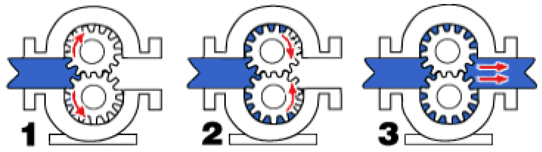
A painting system using a six-axis articulated robot has been developed to paint complex-shaped objects uniformly and efficiently. Particularly, the automobile painting process requires high quality, and methods of spraying paint quickly and precisely have been developed. For the precise fluid transfer, the fluid gear pump is widely used. As shown in
Figure 1, the fluid gear pump operates to control the flowrate using the electronic actuator and the rotational gear.
The fluid gear pump has repetitive disturbances, such as flow ripples, that decrease the precision of the fluid transfer. To compensate for the repetitive disturbances, previous studies have suggested a mathematical model of the repetitive flow ripples. The characteristics of the flow ripple are expressed by the theoretical method according to the number of gear teeth [
1]. The characteristics of the trapped volume between the gear teeth, which cause the flow ripple, can be calculated by a geometric formula [
2]. To express the fluctuation of the flowrate as a mathematical model, a flowrate formula uses an analytical method that considers the shape of the fluid gear pump [
3]. A numerical method has been proposed for analyzing the kinematic flow ripple of a fluid gear pump, which allows more precise mathematical modeling than conventional analytical methods [
4,
5,
6].
The zero phase error tracking controller (ZPETC) and the repetitive controller based on the internal model principle have been applied to various applications for the repetitive disturbance rejection [
7,
8]. The repetitive controller is very effective in servo systems with repetitive disturbances [
9]. For more stable control in systems with periodic disturbances, the repetitive controller can be combined with a low-pass filter [
10]. The discrete wavelet transform-based repetitive controller minimizes the memory used in the repetitive controller and minimizes the tracking error [
11]. To track the desired trajectory while eliminating repetitive disturbances, the repetitive controller can be plugged into a conventional controller such as a proportional-derivative (PD) controller. This plug-in repetitive controller has been applied to the pulse-width modulation (PWM) rectifier and has shown effective performance [
12]. The repetitive controller with a disturbance observer can effectively compensate for the disturbances with non-repetitive frequency components [
13].
Previous studies have proposed control methods to eliminate system disturbances, and the disturbance observer and the repetitive controller are representative examples [
7,
8,
9,
10,
11,
12,
13,
14,
15,
16,
17]. To eliminate multiple disturbances as well as single disturbances, a composite hierarchical anti-disturbance control was proposed [
18]. Active disturbance rejection control was proposed in order to compensate for disturbances that are difficult to model, by automatically updating the parameters of the controller [
19]. Many disturbance rejection methods have been developed, but repetitive controllers can effectively remove periodic disturbances [
20,
21]. As an example of the implementation of repetitive control, repetitive disturbances are effectively removed for servo systems such as optical disk drives and hard disk drives [
22,
23]. In addition, a repetitive controller applied to the rotor of a wind turbine minimized periodic wind disturbance [
24].
For the precise flowrate control of the fluid gear pump-based painting system used in automotive painting processes, this study attempts to eliminate various periods of disturbance for a wide range of flowrate commands. The disturbances in various periods can be expressed by the rotational speed and rotation angle of the motor, relative to the flowrate command. Therefore, a lookup table-based controller can be designed to effectively compensate for periodic disturbances. In this study, the compensation lookup table-based controller corresponding to the flowrate and the rotation angle is experimentally generated through the repetitive controller. To secure robustness against various situations, a closed-loop system consists of the conventional PD controller and a compensation lookup table, in the form of the feedforward controller. The proposed method is evaluated by comparison with the open-loop controller and the conventional PD controller, which are widely used in the industry.
This paper is organized as follows.
Section 2 introduces the robot arm and the fluid gear pump system used in vehicle painting in this study, and it identifies the problems that occur in the precise flowrate control. The
Section 2 presents a repetitive control-based feedback controller that compensates for the repetitive disturbance of the fluid gear pump system. In
Section 3, experimental results are presented for the verification of the proposed control method.
Section 4 presents conclusions and a future direction of study.
2. Materials and Methods
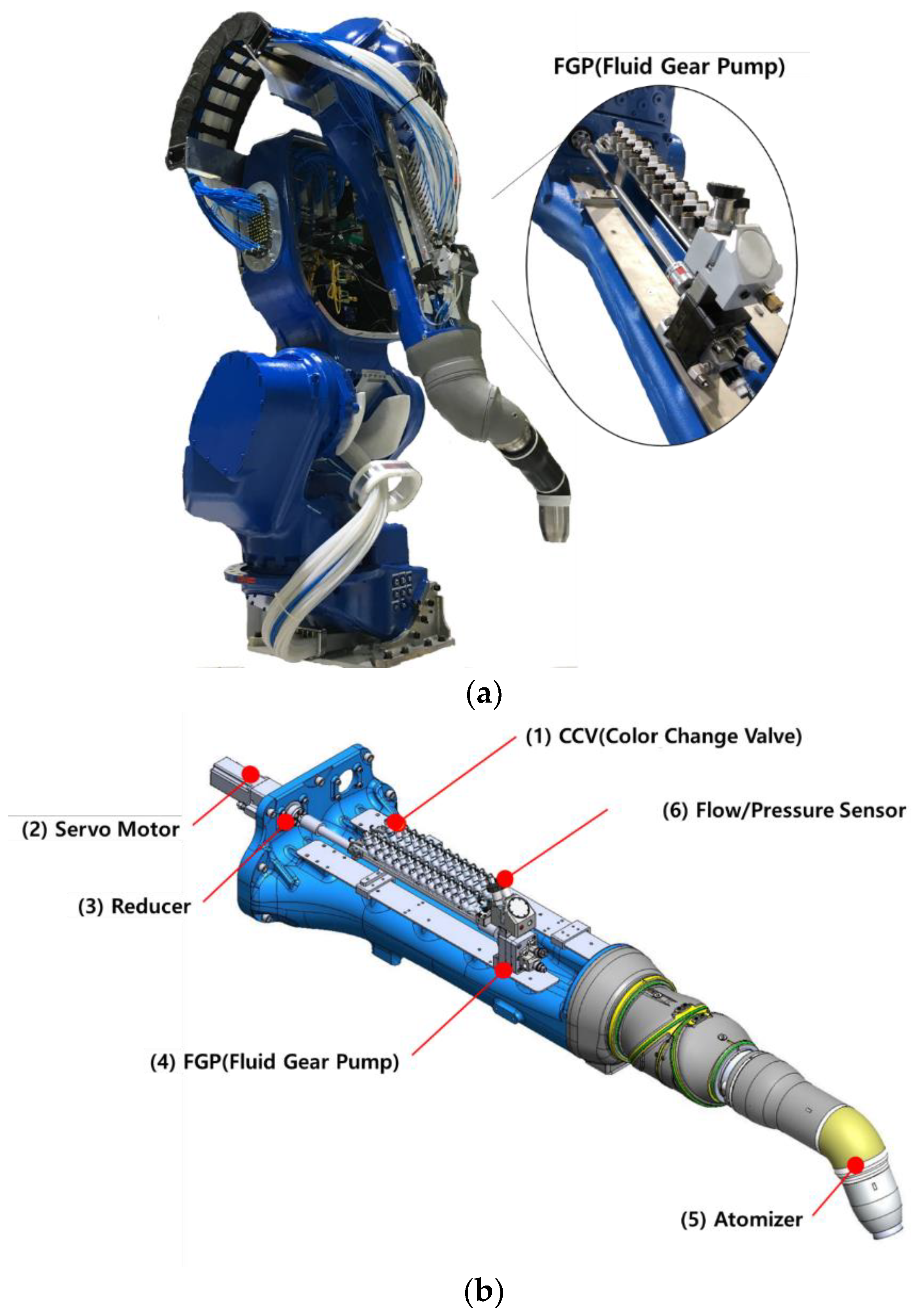
To ensure a high level of painting quality in the automotive painting process, a robotic arm with a fluid gear pump-based painting system is used.
Figure 2a shows the outline of the robotic arm for vehicle painting, and
Figure 2b shows the vehicle painting system based on the fluid gear pump to be controlled in this study. As shown in
Figure 2b(1), the color change valve unit can be used to change the paint color. The servo motor in
Figure 2b(2) is connected to the reducer in
Figure 2b(3) for proper torque. Then, the fluid gear pump in
Figure 2b(4) is used to discharge the paint in the correct amount. The atomizer in
Figure 2b(5) rotates the paint at a high speed and atomizes it before spraying it onto the substrate. The flow/pressure sensor in
Figure 2b(6) can measure the amount of paint dispensed.
In the system of
Figure 2b, the servo motor has a rated power of 200 W and a rated rotational speed of 3000 rpm, and the reducer has a gear ratio of 10:1. The fluid gear pump (DGP 6SAD01) is capable of delivering 6 cc of fluid per revolution, and has 14 teeth. The flow sensor (G250HR, Graco) is capable of measuring fluids with an accuracy of 0.061 cc/pulse at flow rates ranging from 38 to 1900 cc/min. The fluid gear pump-based painting system in
Figure 2a has an output range of 0 to 500 cc/min, so the flow sensor can sufficiently measure the flowrate output. In this study, a fluid with a viscosity of 31.5 cSt at 40 °C (FM AW Hydraulic ISO 32, Guardsman) is used to control the fluid gear pump system.
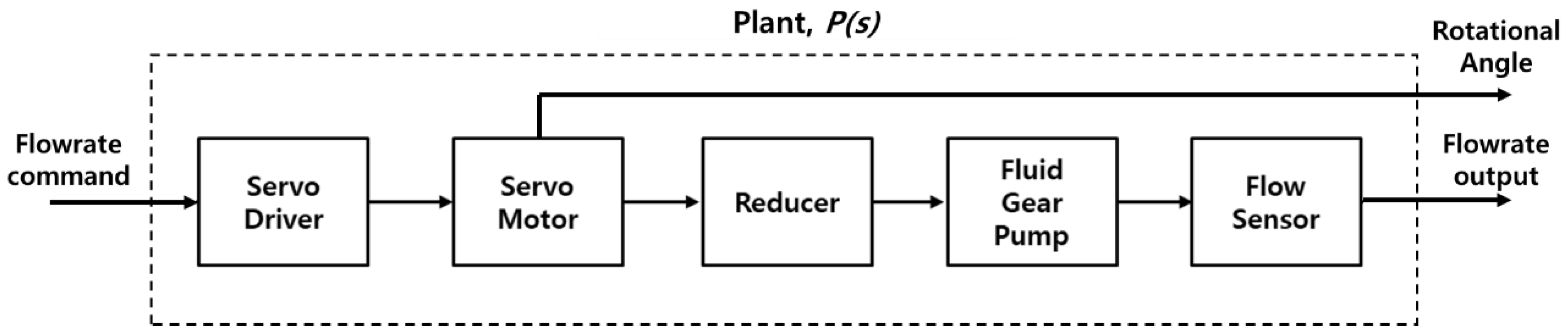
As shown in
Figure 3, the fluid gear pump-based painting system (
Figure 2b) is defined as a transfer function (
) in which the input signal is the flowrate command and the output signal is the flowrate output. When a constant flowrate command is an input to the painting system, the servo motor rotates at the speed corresponding to the reference, and the flowrate output of the fluid transferred through the fluid gear pump is measured from the flow sensor. The rotational angle of the motor can be measured by an encoder.
Figure 4 shows the measurement result of the steady-state flowrate output of
for the constant flowrate command. In
Figure 4a and
Figure 4b, the flowrate commands are 400 cc/min and 100 cc/min, respectively. The results of the open-loop control for the constant flowrate command show that the steady-state flowrate output contains periodic disturbances.
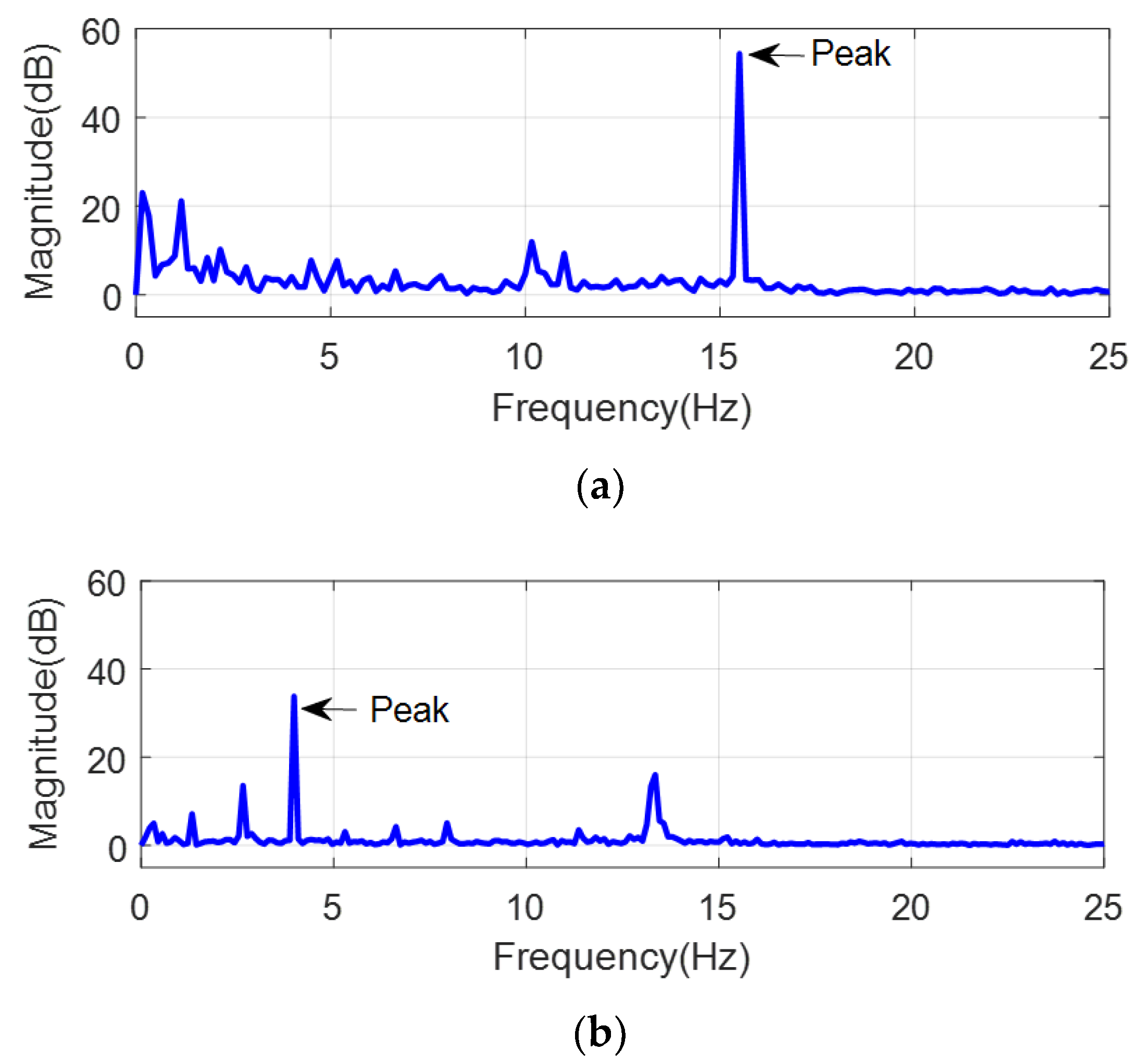
Fast Fourier transform (FFT) is applied for the frequency analysis of the periodic disturbances.
Figure 5a is the result of applying the FFT to the flowrate output of
Figure 4a, and
Figure 5b is the result of its application to the output of
Figure 4b. The peak frequency due to periodic disturbance is 15.556 Hz for the constant flowrate command of 400 cc/min, and 3.972 Hz for 100 cc/min. Since the flowrate command is a fixed value, the peak frequency of the flowrate output is considered as the frequency of the periodic disturbance.
The constant flowrate commands of 100, 200, 300, 400, and 500 cc/min were used to obtain the frequency of the disturbance.
Table 1 shows the peak frequency of the measured flowrate output. Experimental results show that the peak frequency of the flowrate output is as large as the amplitude of the flowrate command. Since the rotational speed of the motor increases as the flowrate command increases, the frequency of the periodic disturbance is proportional to the rotational speed of the motor. Periodic disturbances can also be affected by the angle and the rotational speed of the motor. The periodic disturbances related to the rotational speed and the angle of the servomotor must be compensated for, in order to achieve the precise spraying of the fluid gear pump-based painting system.
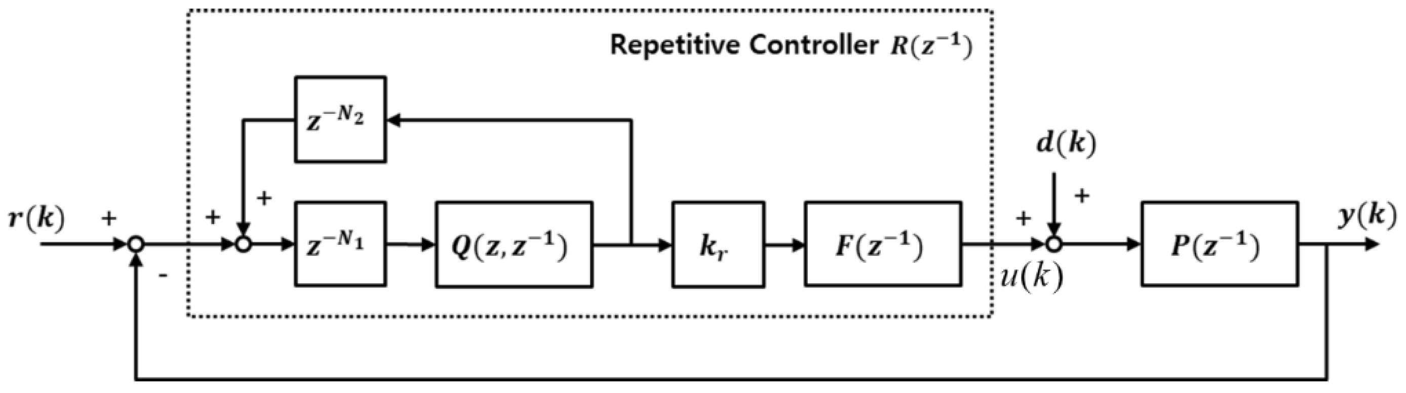
For a closed-loop system in the discrete-time domain given a flowrate command and a plant model, the repetitive controller can be implemented as a block diagram, as shown in
Figure 6. In
Figure 6,
,
, and
denote the reference, output, and disturbance, respectively, and
,
,
and
are the plant model, the repetitive controller, the dynamic compensator, and the low-pass filter, respectively. If
is a period of the repetitive disturbance,
and
satisfy
as delay counts. If the plant model satisfies
and all of the poles of the
are in the unit circle,
and
are established.
To design a repetitive controller for periodic disturbances, the nominal model of the plant (
) in
Figure 3 was experimentally obtained, and expressed in the second-order system in the continuous-time domain as follows:
The poles of P(s) are
in the left-half of the plane, and the stability of the nominal plant model is guaranteed.
is the discrete-time transfer function obtained by using the zero-order hold equivalent in P(s) of Equation (1) at the sampling period of 1 msec, and it is expressed as follows:
Since the poles of are and the zero of is , all of the poles and zeros of exist inside of the unit circle.
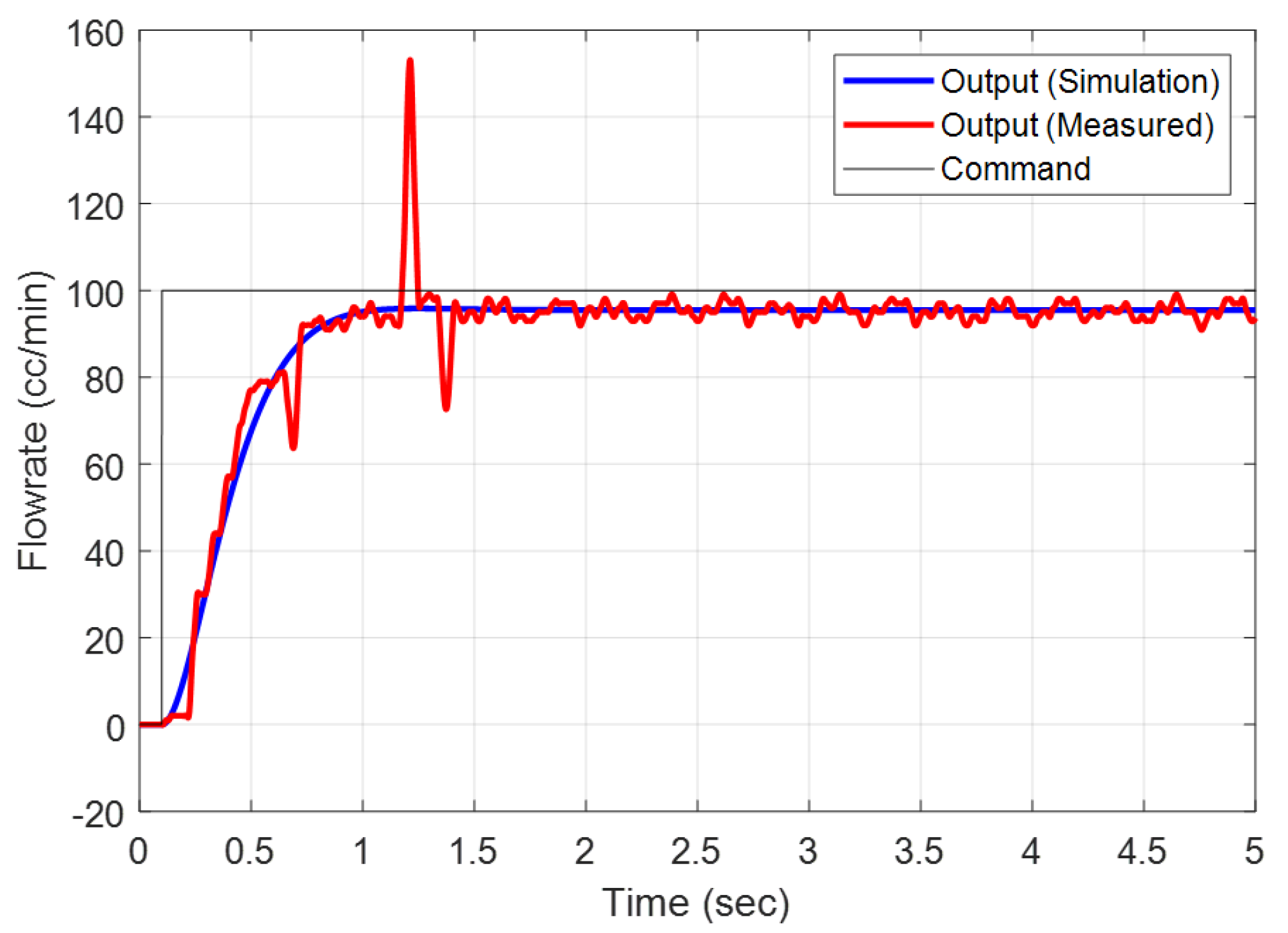
To verify the similarity between the actual plant model and the nominal plant model in Equation (2), the step response for the flowrate command of 100 cc/min is analyzed, as shown in
Figure 7. MATLAB (2018b, Mathworks) was used for the simulation of the nominal plant model. After 2 s in
Figure 7, the mean square error (MSE) between the simulation and experimental results is 2.134 cc/min, and the correlation between the results from 0 to 4 s is
= 0.9384. For the flowrate commands of 100, 200, 300, 400, and 500 cc/min, the simulation results using the nominal plant model are compared with the experimental results in
Table 1, and listed in
Table 2. For the five flowrate commands, all of the MSEs were less than 2.5, and all
were above 0.9. In
Table 2, the MSE was relatively large in the low-frequency range of 100 and 200 cc/min due to the influence of the gear shape and frictions. In conclusion, the nominal plant model of Equation (2) is a transfer function expressing the actual plant model and that can be used for designing repetitive controllers.
To design the repetitive controller, the nominal plant model of Equation (1) can be represented as
=
, and
and
are asymptotically stable polynomial (i.e., all of the poles are located in the unit circle). Note that a closed-loop system including the
and the repetitive controller (
) is asymptotically stable if
satisfies the following conditions [
10]:
where N is the period of periodical disturbance. The closed-loop system containing the repetitive controller of Equation (3) is always asymptotically stable in
[
10]. In this study, the repetitive controller factor (
was set to 0.8 in order to ensure the stability. The transfer function
in the form of a low-pass filter is defined as follows:
The bandwidth of the is 181.7 Hz, including the output range, so the can act as a moving average filter, which effectively removes the measurement noise without reducing the system bandwidth.
When the repetitive controller of Equation (3) is applied to the plant of Equation (2),
Figure 8 shows the repetitive controller output (
u(k)) at the steady state for flowrate commands of 100, 200, 300, and 400 cc/min.
Figure 8 shows two characteristics of the controller output: (1) The controller output changes according to the motor’s flowrate command, and (2) the controller output is synchronized according to the rotational angle of the motor. This means that periodic disturbance occurs depending on the angle and rotational speed of the motor. It is difficult to remove the disturbance only by the repetitive controller if the disturbance of various periods occurs for a wide range of flowrate commands. Therefore, this study proposes a compensation lookup table that removes disturbance according to the rotation angle and rotation speed of the motor.
In this study, the compensation value of the controller output according to each flowrate command is defined as the mean value of the controller output during N samples in the steady state:
where index
i is the kind of constant flowrate i.e., (
). For example, in
Figure 8,
M = 4,
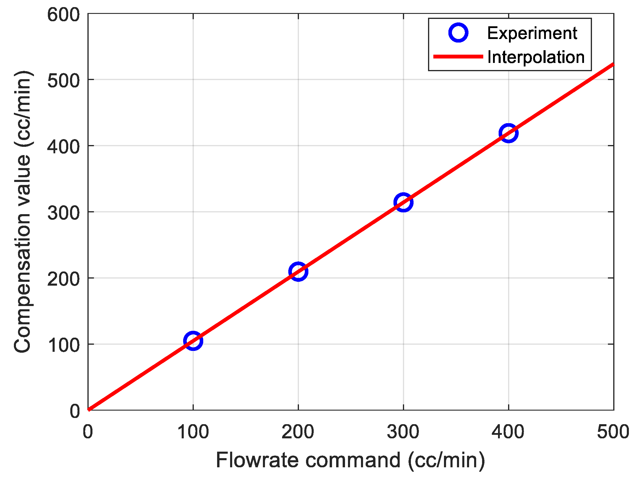
. Thus, Equation (5) gives the average of the controller outputs for N samples at each flowrate command. The sampling period of this study was 1 ms, and N = 10,000 was set to average the controller output for 10 s in the steady state. From Equation (5), the compensation values for the flowrate commands of 100, 200, 300, 400, and 500 cc/min were experimentally obtained, and the linear equation obtained by linear interpolation is expressed as follows:
where
is the compensation value for the flowrate command, and
is the constant flowrate command.
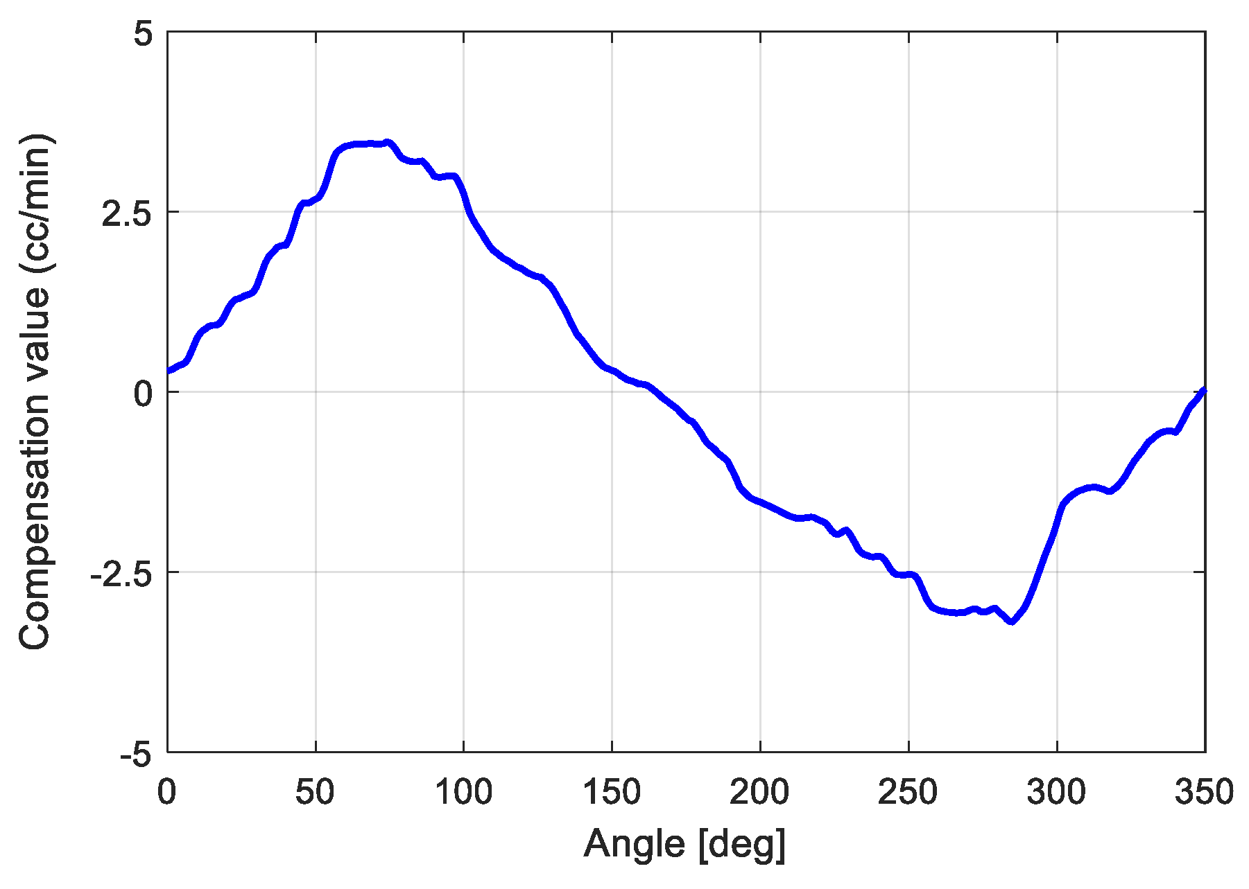
Figure 9 shows the experimental data and Equation (6). The compensation value according to the rotation angle of the motor is obtained by the following equation:
where
is the mean value during N samples of the controller output for the
i-th flowrate command, as shown in Equation (5). Equation (7) first obtains the zero mean value signal (
) from the controller output for each constant flowrate command. Secondly, Equation (7) obtains an average value of M zero mean value signals at every angle.
Figure 8 shows the compensation value according to the condition of
M = 4, and the rotation angle of the motor obtained from Equation (7) is shown in
Figure 10.
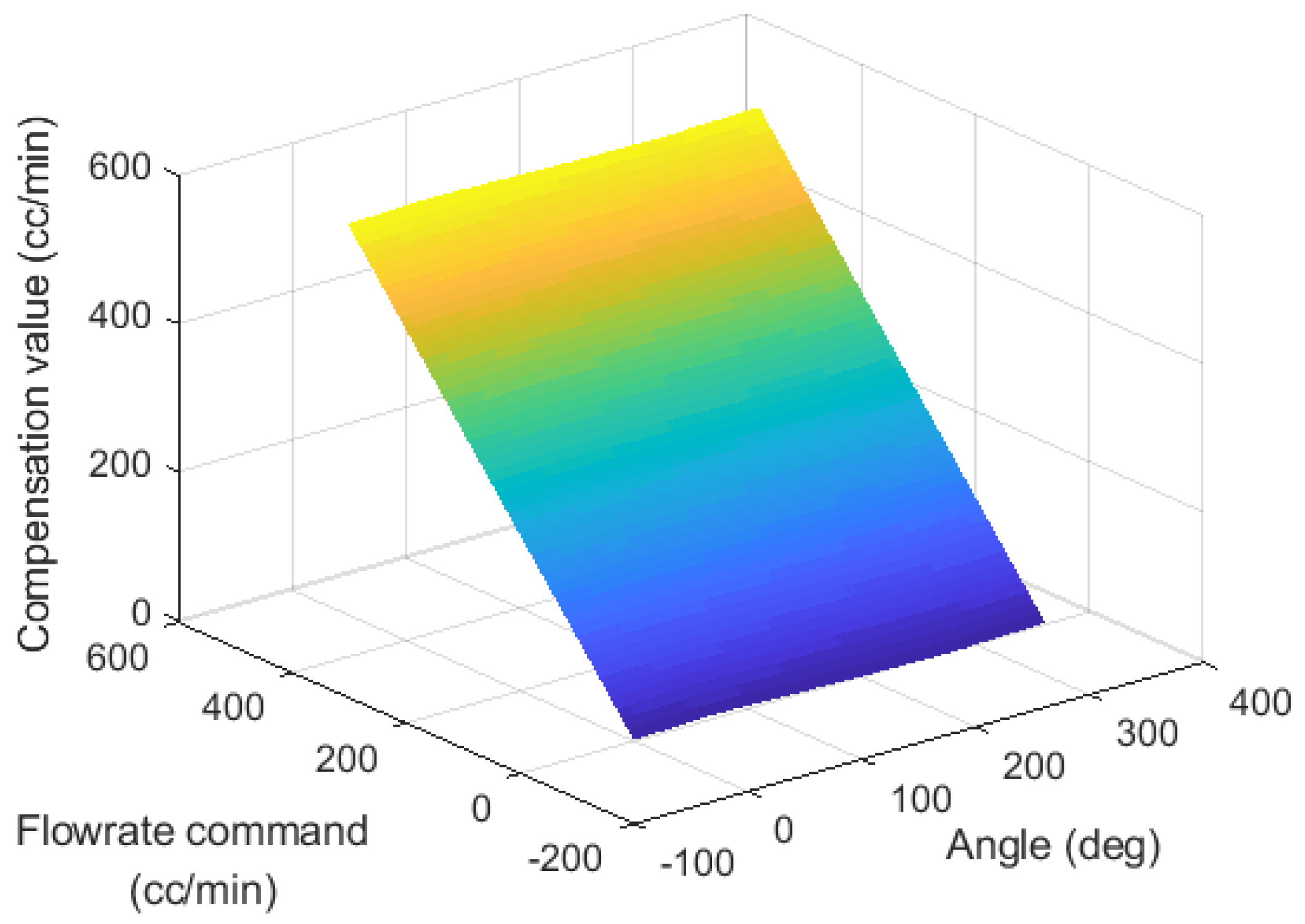
The flowrate command dependent compensation value and the angle-dependent compensation value obtained experimentally in
Figure 9 and
Figure 10, respectively, can be expressed as a lookup table, as shown in
Figure 11. The input data of the compensation lookup table is the flowrate command and the current rotation position. Compensation lookup tables can obtain optimal compensation values that can remove periodic disturbances from input data.
A closed-loop system with feedforward control based on a compensation lookup table in a conventional feedback controller is proposed as shown in
Figure 12. The symbols
,
,
and
denote the flowrate command, flowrate output, disturbance, and rotational angle of the motor, respectively.
and
are the plant model and feedback controller, respectively. The feedback controller—such as a PD controller—secures robustness, tracking performance, and the stability of a closed-loop system. The feedforward controller using a compensation lookup table effectively compensates for periodic disturbances.
3. Results
The proposed method in
Figure 12 is experimentally evaluated. For the efficient tracking control, the PD controller is used as the feedback controller
in
Figure 12. Since the integral action can amplify the sensor noise and degrade the stability of the closed-loop, the proportional integral derivative (PID) controller is not used. The feedback controller follows the flowrate command (
) of 100, 150, and 400 cc/min, respectively. The experimental results of the measured flowrate output in the steady state are shown in
Figure 13 and
Table 3. The
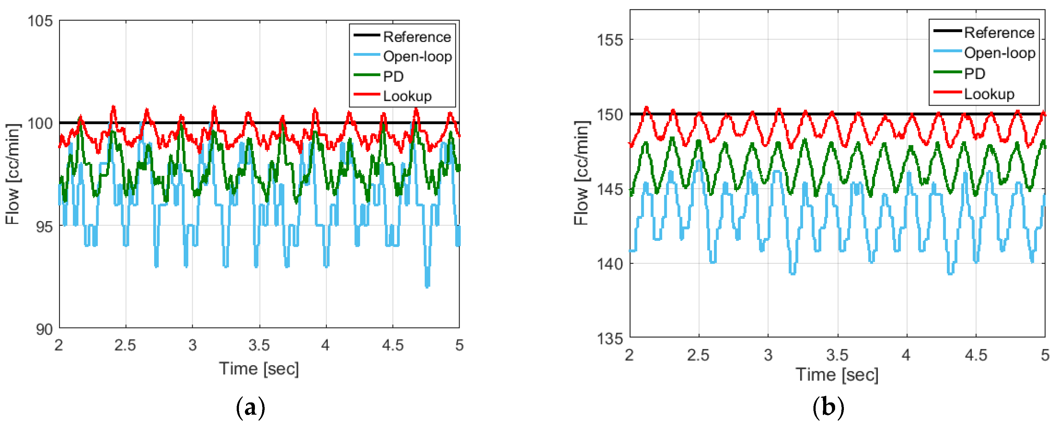
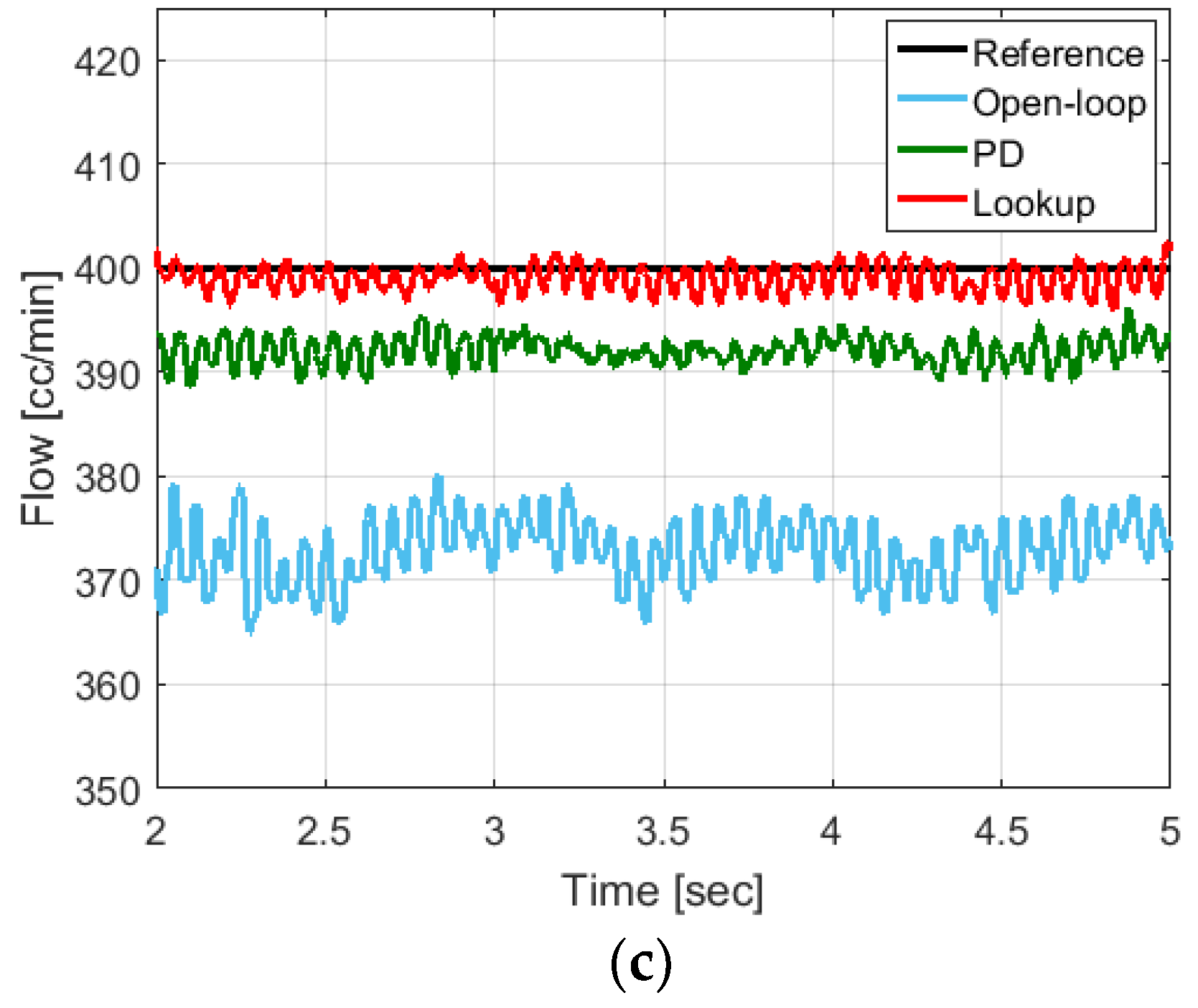
Figure 13a–c shows the experimentally measured flowrate outputs of 100, 150, and 400 cc/min, respectively. As shown in
Figure 13, the blue line is the measured output of the open-loop system (Open-loop), the green line is the closed-loop system only using the PD controller (PD), and the red line is the closed-loop system using the compensation lookup table-based feedforward controller and the PD controller (Lookup).
As shown in
Figure 13a–c, the open-loop control system showed that the root mean square (RMS) values of the steady-state error were 3.9604, 7.1526, and 27.2863, respectively. In the closed-loop system only using the PD controller, the RMS errors between the flowrate command and the measured output were 2.3493, 3.6986, and 8.0320, respectively. The two control systems could not effectively remove the periodic disturbances. On the other hand, in the case of the proposed control method, the RMS values of tracking error were 0.7275, 1.1953, and 1.6392, respectively. The RMS values of the proposed method are much less than the RMS values of the open-loop system and the PD controller. In the case of the open-loop control system and the PD controller, the flow feedback at the steady state did not reach the flow command in the biased form. On the other hand, the proposed controller compensated the flowrate dependent value in the compensation lookup table as the feedforward type, so that the biased characteristics at the steady state were improved remarkably. Non-biased flow feedback that follows the flowrate command precisely in the painting process is essential. If the flow feedback does not reach the flowrate command sufficiently, there may be a lack of coating. In contrast, defects such as sagging may occur if the flow feedback is higher than the flowrate command. The experimental results show that the proposed controller can reduce the steady-state error significantly for the low-frequency flowrate commands, as well as for the high-frequency flowrate commands compared to the open-loop control system.
From the experimental results, the proposed control method can reduce the fluctuation amplitude, which is the minimum peak to the maximum peak difference in the steady-state error. The compensation lookup table-based feedforward controller showed that the mean values of fluctuation amplitude were 1.8790, 2.1891, and 3.3696, respectively, when the flowrate commands were 100 cc/min, 150 cc/min, and 400 cc/min. In the closed-loop system only using the PD controller, the mean values of fluctuation amplitude were 3.3110, 3.3740, and 3.5198.
In the low-speed flowrate command, the fluctuation amplitude of the proposed controller is low, whereas the fluctuation amplitude is as high as much as the conventional PD controller at high-speed flowrate command. The influence of the flowrate dependent compensation value is relatively greater than in the rotational angle-dependent compensation value at a high-speed flow rate command. Therefore, there is a limitation to remove periodic disturbances at high-speed flowrate commands effectively. However, the proposed controller can be effectively used because most of the flowrate commands are operated in the low-speed range of 100 to 150 cc/min in the painting process.


