Article

Equivalent Circuit Model of Novel Solid Rotor Induction Motor with Toroidal Winding Applying Composite Multilayer Theory

1
School of Electrical Engineering and Automation, Henan Polytechnic University, Jiaozuo 454000, China
2
College of Electric Engineering, Zhengzhou University, Zhengzhou 450001, China
3
Department of Electrical Engineering and Electronics, University of Liverpool, Liverpool L69 3BX, UK
*
Author to whom correspondence should be addressed.
Appl. Sci. 2019, 9(16), 3288; https://doi.org/10.3390/app9163288
Submission received: 22 July 2019 / Revised: 7 August 2019 / Accepted: 8 August 2019 / Published: 11 August 2019

Abstract

:
In this work, a novel solid rotor induction motor with toroidal winding (N-TWSRIM) is proposed and its structure and main structural parameters are given. The operating principle is analyzed in accordance with the movement of the armature magnetic field at different times. An equivalent circuit model (ECM) of the N-TWSRIM is established based on composite multilayer theory to analyze and calculate motor performance quickly and accurately. Electromagnetic performance, which includes output torque, stator current, and power factor under different slip, is calculated with ECM, and its results are compared with those of the finite element method. A prototype of the N-TWSRIM is built and experimented on to validate the correctness of the operating principle and ECM. Experimental results on stator current and torque are consistent with the finite element and analytical results.

1. Introduction

The solid rotor induction motors (SRIM) is applied in many fields due to its simple structure, high reliability, and good starting performance [1]. Toroidal winding structures, such as high-frequency inductors, transformers, and electric machines, are used in various applications because of their short end winding, low maintenance cost, and flexible speed regulation [2,3,4]. Applying toroidal winding to SRIM, results in a solid rotor induction motor with toroidal winding (TWSRIM) that combines the advantages of a solid rotor and toroidal winding can be obtained [5]. The equivalent circuit model is an important way to achieve motor design and performance analysis [6]. In order to quickly and intuitively analyze the performance of TWSRIM, it is crucial to establish an equivalent circuit model.
composite SRIM consists of steel and copper layers. The common equivalent magnetic circuit method has difficulty analyzing the electromagnetic field and calculating the equivalent circuit parameters. Therefore, finite element methods (FEMs) are generally used to analyze composite SRIM [7,8,9]. However, FEMs require a large amount of calculation time. To address this disadvantage, Reference [10] proposed a multilayer theory to analyze a smooth solid rotor induction motor. Reference [11] provided a novel multi-slice and multi-layer method for a novel dual stator solid rotor axial flux induction motor. Reference [12] developed a semi-analytical 3D model based on Fourier analysis; this model can calculate the fringe field in a 3D slotted structure. Moreover, several complex propagation constants have been proposed to calculate composite rotor parameters [13,14].
Toroidal windings are widely used in various types of motors [15,16,17,18,19]. Reference [15] conducted a dynamic analysis of a toroidal winding switched reluctance motor (TSRM). Reference [16] proposed a new type of TSRM with a single, continuous, multi-wire winding and compared its performance with that of a conventional switched reluctance motor. Reference [17] developed a novel self-bearing motors based on a toroidally-wound brushless DC motor. To improve machine torque density and efficiency substantially. Reference [18] presented a novel toroidally wound permanent magnet machine. Meanwhile, a complex study of the performance of an outer rotor induction motor with multipole stator winding was performed in [19].
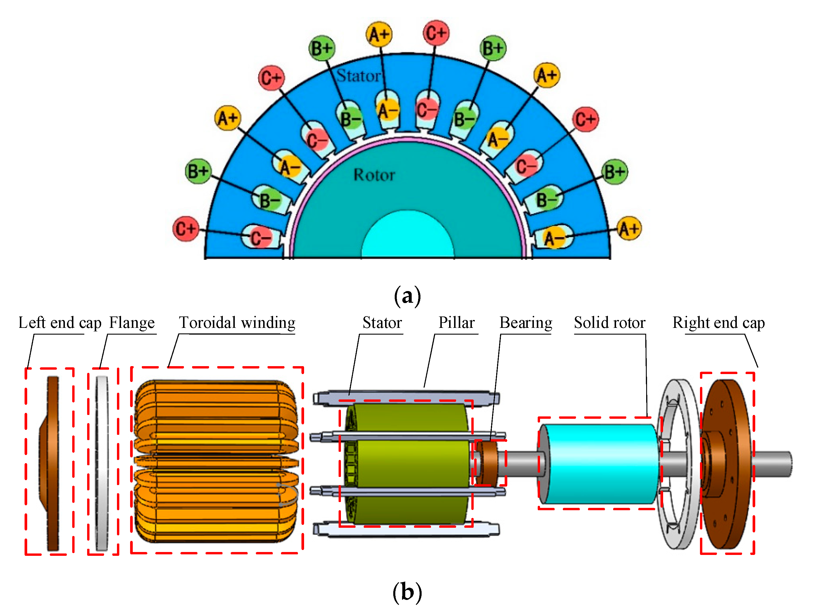
In this paper, a novel solid rotor induction motor with toroidal winding (N-TWSRIM) is proposed. For the N-TWSRIM, composite multilayer theory is used to calculate the motor parameters. Section 2 presents the motor structure, main structure parameters and operating principle of N-TWSRIM. Section 3 introduces the established ECM, and the parameters are calculated with composite multilayer theory. 
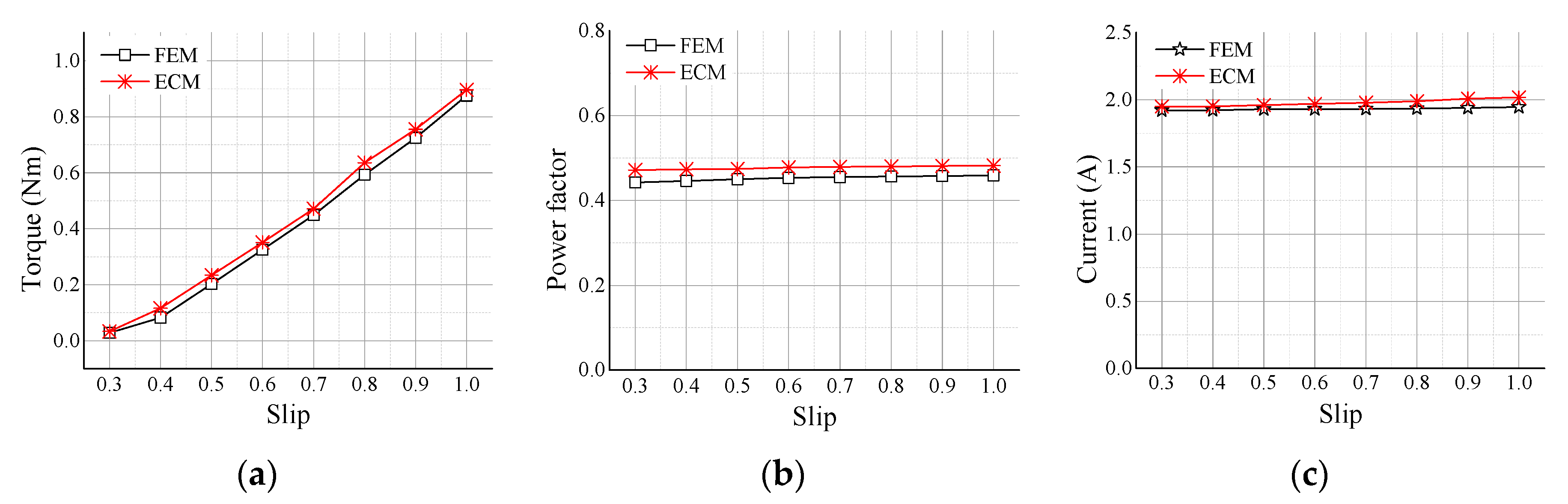
Section 4 presents the analysis results for different copper layer thicknesses. Such results are compared with those of FEM. Section 5 shows the manufacturing and testing of a simple prototype. The correctness of ECM, FEM, and the operating principle are also verified. Section 6 provides the conclusions.

2. Structure and Operating Principle of the N-TWSRIM

2.1. Motor Structure

Figure 1 shows the stator winding wiring diagram and the structure of N-TWSRIM. The external surface of the stator core is welded with many pillars, which are connected with flanges. To increase the mechanical strength of the motor, the flanges are connected to an end cap. The N-TWSRIM relies on rotor bearings, flanges, and end caps to support its weight. Differently from the situation in conventional motors, the windings of N-TWSRIM is distributed in the same radial direction and a coil is formed by the inner and outer winding surrounding the yoke of the stator.
The current in the same side winding has the same direction. Each phase winding is composed of eight coils connected in a forward direction. The main parameters of the N-TWSRIM are given in Table 1.

2.2. Operating Principle

The magnetic field in the motor changes due to the special winding connection of the N-TWSRIM. As a result, a new magnetic field is created. Figure 2 shows the three-phase winding supply current waveform. The operating principle is presented as follows.
Table 2 provides a list of the current directions for the three-phase winding at six time points (“+” for inflow and “−” for outflow).
Figure 3 shows the changes in the armature magnetic field at different times. As we can see from Figure 3, the magnetic field of the motor is constantly changing at different times and the magnetic field of each pole also changes but changes periodically. We can see that the three-slot unit motor can form a pair of pole armature magnetic fields and change periodically.
The special winding form revises the magnetic field of the motor, and the pole number is doubled. We use 1/4 N-TWSRIM as an example to analyze the change in the N-TWSRIM magnetic field., Figure 4 shows the air-gap flux density and the magnetic field distribution at different times.
From Figure 4 it can be clearly observed that any phase voltage amplitude is maximum value and the magnetic field distribution area is equal, as shown in Figure 4b,d. When any phase voltage amplitude is zero, the magnetic field is divided into unequal magnetic fields in two regions, as shown in Figure 4a,c. The transitional magnetic field is shown in Figure 4d.

3. Equivalent Circuit Model of the N-TWSRIM

The equivalent circuit is the main method used to study the electromagnetic theory, working characteristics, and parameter design of SRIM. The impedance of the equivalent circuit parameters of SRIM is critical to the design calculations for the motor, whose ECM is shown in Figure 5. The equivalent circuit can be used to represent the voltage, current, and energy conversion relationship between the stator and the rotor.
In this model, U 1 is the input phase voltage, I 1 is the stator current, R 1 is the stator winding resistance, X 1 is the stator reactance, E is the electromotive force, X mg is the excitation reactance, I r is the rotor current, R cu is the equivalent resistance of the copper layer, R steel is the equivalent resistance of the steel layer, X cu is the equivalent reactance of the copper layer, X steel is the equivalent reactance of the copper layer, R r is the rotor equivalent resistance, and Z r is the rotor equivalent reactance.
In order to analyze the complex eddy current field distribution in a solid rotor and calculate the rotor equivalent impedance, the following basic assumptions are used:
1. The Carter coefficient K c is used to consider the stator core slotting effect.
2. The motor is deployed in the circumferential direction and the stator and rotor extend infinitely along the axial direction.
3. The harmonic components in the field are not considered and the displacement current is ignored.
4. The stator winding current is equivalent to the current sheet at the interface of the air gap and stator. The current layer is infinitely long along the circumference but the current layer thickness is ignored.
5. The end effect is expressed as end effect coefficient K e .
On the basis of the traditional multilayer model [20], 
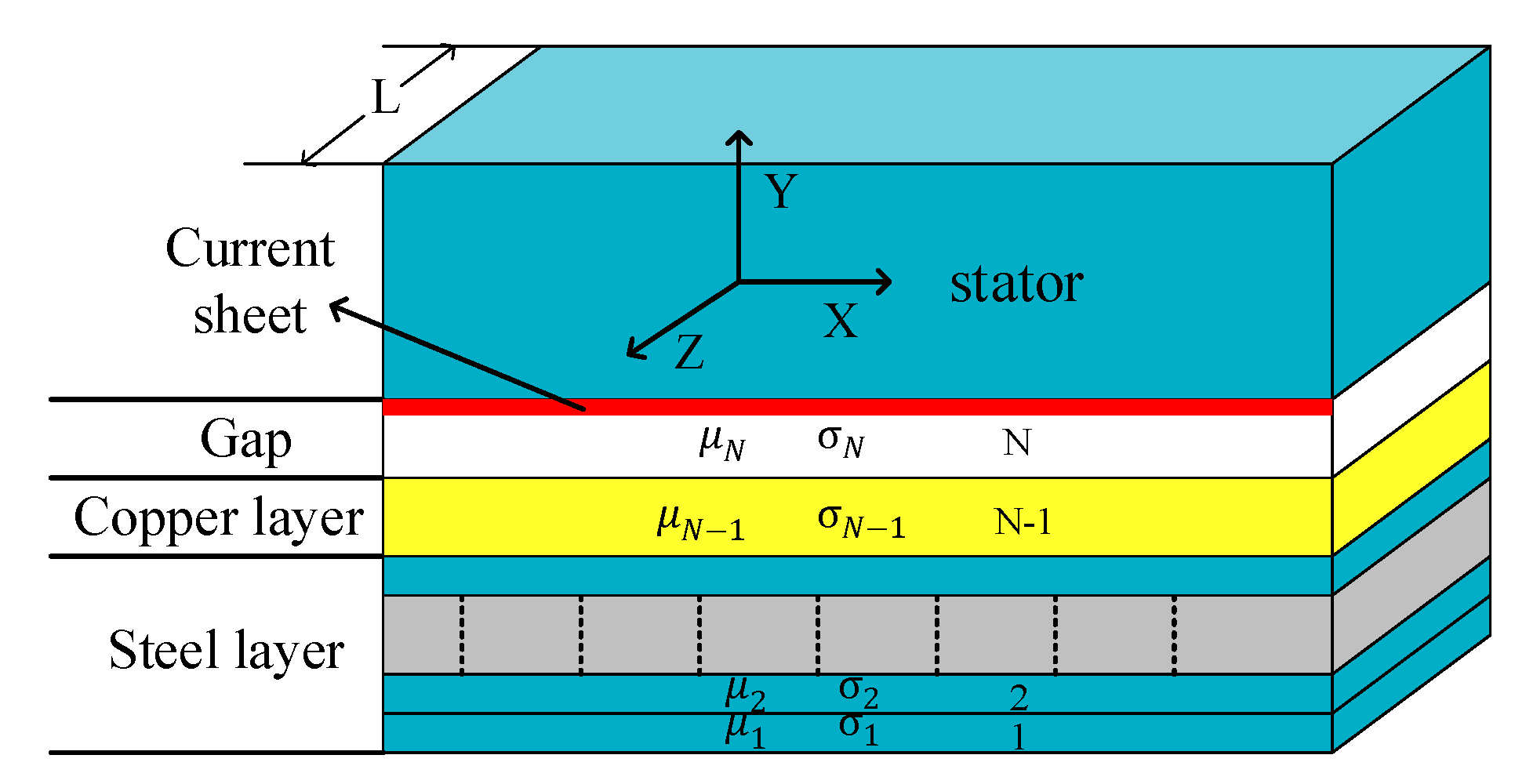
Figure 6 shows the composite multilayer model of the N-TWSRIM, in which the rotor is divided into N layered regions. The 1 ~ N 2 layers represent the steel layer, the s   N layer represents the air gap, and the N 1 layer represents the copper layer. In general, the more the number of layers is divided, the higher the corresponding calculation accuracy. σ i is the conductivity of each layer and μ i is the permeability of the i layer. X is the circumferential direction, Y is the radial direction, and Z is the axial direction.
The stator winding current is equivalent to the current sheet at the interface of the stator and air gap, as shown in Figure 6. The internal surface current J of the stator is represented by Equation (1).
J = J 0 e j ( ω 1 t a x )
where J 0 is the magnitude of the stator interface current density, a = π / τ , τ is the pole pitch, and ω 1 is the angular frequency. J 0 can be expressed as
J 0 = 2 2 m 1 K d p W π D i 1 I 1
where m 1 is the stator phase number, K d p W is the number of effective conductors in series per phase, I 1 is the current of the stator phase, and D i 1 is the diameter of the stator inner.
According to this assumption, the electromagnetic field relationship can be expressed as
{ B ˙ = B x e ˙ x + B y e ˙ y E ˙ = E z e ˙ z
where B ˙ is the magnetic density, H ˙ is the magnetic field intensity, and e ˙ x , e ˙ y , e ˙ z represent the unit vectors in the X, Y, and Z directions, respectively.
According to Maxwell’s equations, the equations in the layer can be expressed as shown in Equations (4) and (5).
{ × H ˙ = J ˙ × E ˙ = B ˙ / t
{ J ˙ = σ E ˙ B x = μ i H x
The equation can be expressed as shown in Equation (6).
{ d 2 B y d y 2 = ( a 2 + j ω i μ i σ i ) B y E z = ω i a B y H x = 1 j μ i a d B y d y
By solving Equation (6), Equation (7) becomes available.
{ B y = A c o s h ( γ i y ) + B s i n h ( γ i y ) H x = γ i j μ i a [ A s i n h ( γ i y ) + B c o s h ( γ i y ) ]
where γ i = ( a 2 + j ω i μ i σ i ) 1 / 2 .
Equation (8) gives the boundary conditions for each layer and Equation (9) gives the transfer matrix for the electromagnetic field.
{ y = 0 ,         B y = B y i 1 ,         H x = H x i 1 y = b i ,       B y = B y i ,       H x = H x i
where y = 0 is the junction of the i 1 layer and i layer, b i is the i layer thickness, H xi is the tangential magnetic field intensity of the i layer, and B y i is the radial magnetic flux density of the i layer.
[ B y i H x i ] = [ cos h ( γ i b i ) 1 β i sin h ( γ i b i ) β i sin h ( γ i b i ) cos h ( γ i b i ) ] [ B y i 1 H x i 1 ]
where β i = γ i / ( j a μ i ) .
The overall boundary conditions are given as
{ H x 1 = β 1 B y 1 H x n = J 0
The difference between composite multilayer theory and traditional multilayer theory is the difference in the calculation method of the N − 1 layer (copper layer), in which composite multilayer theory uses the propagation constant to calculate the copper layer parameters.
Figure 7 shows a block diagram of the calculation process for the N-TWSRIM multilayer composite model. The explanation of the relevant steps is as follows.
(1)
N is an arbitrary value of the number of layers, and, generally speaking, the larger N is, the thinner each layer is and the more accurate the results are, but the greater the calculation time is.
(2)
Set the stator current I 1 and μ 1 ~ μ N 2 values based on actual motor parameters.
(3)
The magnetic field components H x i ,   H y i and B y i ( i = 1 ~ N ) are calculated by the transfer matrix (7) and boundary condition (8). Thus, the resultant H i = H x i 2 + H y i 2 is derived. To consider the nonlinearity of the rotor, the B H curve is represented [21].
μ = K t H ( 1 n ) / n
For the N-TWSRIM rotor steel K t 0.85 ,   t 12 . By applying H i into Equation (11), the new permeability μ i i is obtained.
(4)
According to the μ i i transfer matrix, magnetic field intensity H x n is calculated. A loop ensures that H xn   = J 0 .
(5)
When the cycle meets the conditions, the steel layer impedance Z steel can be obtained according to Equation (12).
Z s t e e l = 4 m 1 ( K d p W ) 2 π D 2 Z N 2 L e K e
Z N 2 = s ω 1 a B y N 2 H x N 2
where D 2 is the diameter of the rotor, Z N 2 is the wave impedance, Z N 2 = ( s ω 1 a ) ( B y N 2 / H x N 2 ) , and s is the slip. H x N 2 is the tangential magnetic field intensity of the N 2 layer and B y N 2 is the radial magnetic flux density of the i = 1 ~ N 2 layer.
(6)
When the traditional multilayer theory is used to calculate the copper layer parameters, the iteration speed is slow. So, to calculate the equivalent circuit parameters of the copper layer, the propagation constant K c u is used [11], as shown in Equations (14)–(16).
Z c u = J ω c u μ c u K c u 1 K c u b c u L e K e s τ
K c u = ( α c u 2 + β 2 ) 1 2
σ c u = ( j ω c u μ c u σ c u ) 1 2
where b c u is the copper layer thickness, ω c u is the copper layer angular frequency, β = π / τ , and σ c u is the conductivity of copper.
(7)
The rotor impedance is calculated by Equation (17).
Z r = Z c u Z s t e e l Z c u + Z s t e e l
(8)
We can calculate the stator voltage U 11 by the rotor impedance. When the accuracy of U 1 and U 11 is not satisfied, the loop continues. When the accuracy is satisfied, the values of I 1 ,   μ i ,   H x i ,   B y i are given.
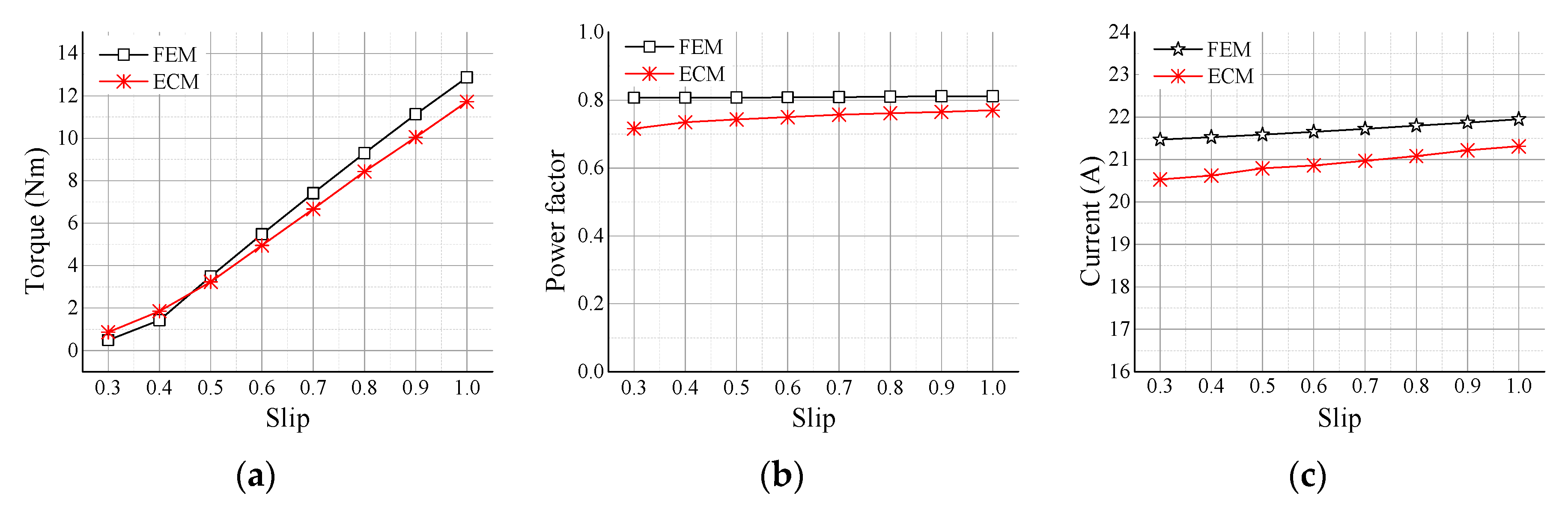
The rotor equivalent parameters of the solid rotor motor of the toroidal winding are calculated in cases where the stator winding phase voltage is 220 V and the voltage frequency is 50 Hz. The results are shown in Table 3. Hence, the output torque, stator current, and power factor of the N-TWSRIM can be computed accordingly.

4. Simulation Result Comparisons of the N-TWSRIM

4.1. Non-Copper Plating Model

To verify composite multilayer theory, when the thickness of the copper layer is 0, a 2D non-copper plating model of N-TWSRIM is established. The flux distribution is shown in Figure 8.
The electromagnetic properties of the non-copper plating model, including output torque, stator current, and power factor, are calculated by ECM and FEM. The results are shown in Figure 9 and Table 4.
Comparison of the analytical and finite element results shows that the torque gradually increases with the increase in slip, which is similar to the traditional solid rotor torque curve and has monotone increasing characteristics. However, the stator current and power factor only increase slightly as the slip increases, and almost no change is observed. This feature makes N-TWSRIM capable of running at overload or block conditions for a long time, and the proposed motor can be used for specific applications. However, according to the torque and power factor curves, the torque and power factor of the motor are low. This disadvantage can be improved by copper plating on the rotor surface.

4.2. Copper Plating Model

A composite structure solid rotor is applied to enhance the performance of N-TWSRIM. This composite rotor consists of steel and copper layers. The radial magnetic field and the induced electromotive force of the rotor increase because the relative magnetic permeability of the steel layer is much larger than that of the copper layer. Hence, the output torque and power factor of the N-TWSRIM will be improved. When the thickness of the copper layer is greater than 0, a 2D finite element model is established and its flux distribution is given in Figure 10. The analytical results are compared with the FEM results to verify composite multilayer theory.
Figure 10 shows that the depth of penetration of the magnetic lines increases when the copper plating rotor is used. This phenomenon is also consistent with the analysis results. The electromagnetic properties of the copper plating model, including output torque, stator current, and power factor, are calculated with ECM and FEM. Figure 11 and Table 5 show the comparison results.
Figure 11 and Table 5 show that the copper-plated and non-copper-plated models exhibit the same trends of output torque, stator current, and power factor as the slip changes. When the copper layer thickness is greater than 0, the power factor is considerably improved because eddy current effects are generated in the copper layer, and the power factor increases when the copper-clad rotor is used. In addition, the amplitude of the stator current at full load is only slightly increased compared with the amplitude of stator current at no load, indicating that the motor can work for a long time under large slip conditions. The calculation result of ECM has good consistency with the calculation results of FEM, and the maximum error does not exceed 15%.

5. Experimental Verification

A non-copper plating prototype is built (as shown in Figure 12) to verify the accuracy of the results presented above, and experimental tests are conducted. The motor experimental platform is shown in Figure 13. The speed and torque of the prototype were measured with a torque-speed sensor. The load torque is provided by the eddy current brake and the eddy current brake and measuring instrument are connected by the coupling. The power supply of the prototype is provided by Frequency converter. Another copper plating prototype is being processed and will be presented in future research.
A prototype test is carried out with the voltage RMS value is 220 V and the frequency is 50 Hz. The experimental results have been compared with the finite element results. The rotor parameters in the experimental prototype cannot be measured separately, so the output torque and stator current at different slips were selected as comparison indicators. Table 6 provides the analytical, finite element, and experimental current values for different slip values.
Table 6 shows that the stator currents error of the ECM and measured is less than 5%, which means the stator current of ECM is consistent with the measured results. Figure 14 shows the torque-slip curve of ECM, FEM, and the experiment. Table 7 gives the analytical, finite element, and experimental output torque values for different slip values.
According to Figure 14 and Table 7 of the revised manuscript, it can be seen that the ECM and test error are within 15% and the error at the large slip is less than 5%, meeting the accuracy requirements. The causes of the error are as follows.
  • When the prototype is tested, the power supply contains harmonic components, so the stator current obtained by the experiment is slightly larger than ECM and FEM.
  • In the calculation process of composite multilayer theory, the influence of harmonics is ignored and the obtained resistance and reactance value will cause errors.
  • The selection of some empirical coefficients in the ECM calculation process will produce errors.

6. Conclusions

A novel SRIM with toroidal winding has been presented and studied. It combines the advantages of a solid rotor and toroidal winding, and it can be used not only under harsh conditions—when a fault (short or open circuit) occurs in either coil, the toroidal configuration can solve this problem by replacing a single coil. Hence, the reliability of the motor under various faulty conditions is enhanced. Moreover, an ECM is established based on composite multilayer theory to evaluate the performance of N-TWSRIM quickly and accurately. The proposed method is suitable for non-copper and copper plating models. The electromagnetic performance, which includes output torque, power factor, and stator current under different slip conditions, is calculated, and the results of the non-copper and copper plating models were verified by 2D-FEM. A non-copper plating prototype is built and tested. The stator current and torque were also measured experimentally to verify the 2D FEM and analytical results. Compared with FEM, the proposed ECM can analyze and calculate more intuitively and quickly for the N-TWSRIM.

Author Contributions

Conceptualization, H.F., X.C. and J.S.; Software, H.F. and X.C.; Validation, Y.H. and J.S.; Formal Analysis, X.C.; Writing-Original Draft Preparation, H.F. and X.C.; Writing-Review & Editing, H.F. and X.C.; Funding Acquisition, C.G. and J.S.

Funding

This work was supported by the National Natural Science Foundation of China under grants 51777060 and 51277054 and the Key Science and Technology National Program of Henan Province (no. 192102210230).

Acknowledgments

The prototype was produced by Yokogawa Robot (Shenzhen) Co., Ltd. Thanks to Shu-hua Wang for technical support. The motor control system was provided by Zhengzhou Runhua Industrial Automation Equipment Co., Ltd.; thanks to Ying-sheng Li for providing technical support.

Conflicts of Interest

The authors declare no conflict of interest.

References

  1. Zhang, M.Y.; Tang, X.G.; Lin, J.M. Development and Prospect of New Type Derived Solid Rotor Asynchronous Motors at Home and Abroad. Electr. Eng. 1991, 3, 13–15. [Google Scholar]
  2. Eroglu, A. Complete Modeling of Toroidal Inductors for High Power RF Applications. IEEE Trans. Magn. 2012, 48, 4526–4529. [Google Scholar] [CrossRef]
  3. Hernandez, I.; de Leon, F.; Gomez, P. Design Formulas for the Leakage Inductance of Toroidal Distribution Transformers. IEEE Trans. Power Deliv. 2011, 26, 2197–2204. [Google Scholar] [CrossRef]
  4. Gao, C.X.; Gao, M.Z.; Si, J.K.; Hu, Y.H.; Gan, C. A Novel Direct-Drive Permanent Magnet Synchronous Motor with Toroidal Windings. Energies 2019, 12, 432. [Google Scholar] [CrossRef]
  5. Cui, X.; Si, J.K.; Feng, H.C.; Gao, C.X.; Cheng, Z.P. Operating Principle and Electromagnetic Characteristic Analysis for Large-Small Pole Solid-Rotor Induction Motor with Toroidal Windings. Trans. China Electrotech. Soc. 2019, 34, 1850–1856. [Google Scholar]
  6. Lv, G.; Yan, S.Q.; Zeng, D.H.; Zhou, T. An Equivalent Circuit of the Single-sided Linear Induction Motor Considering the Discontinuous Secondary. IET Electr. Power Appl. 2019, 13, 31–37. [Google Scholar] [CrossRef]
  7. Markovic, M.; Perriard, Y. An analytical solution for the torque and power of a solid-rotor induction motor. In Proceedings of the IEEE International Electric Machines & Drives Conference (IEMDC), Niagara Falls, NY, USA, 15–18 May 2011; pp. 1053–1057. [Google Scholar]
  8. Si, J.K.; Feng, H.C.; Ai, L.W.; Hu, Y.H.; Cao, W.P. Design and Analysis of a 2-DOF Split-Stator Induction Motor. IEEE Trans. Energy Convers. 2015, 30, 1200–1208. [Google Scholar] [CrossRef] [Green Version]
  9. Lee, J.; Kim, D.; Baek, S.; Rhyu, S.; Kwon, B. Newly Structured Double Excited Two-Degree-of-Freedom Motor for Security Camera. IEEE Trans. Magn. 2008, 44, 4041–4044. [Google Scholar]
  10. Lim, D.K.; Yi, K.Y.; Woo, D.K.; Yeo, H.K.; Ro, J.S. Analysis and Design of a Multi-Layered and Multi-Segmented Interior Permanent Magnet Motor by Using an Analytic Method. IEEE Trans. Magn. 2014, 50, 1–8. [Google Scholar] [CrossRef]
  11. Hong, C.C.; Huang, W.X.; Hu, Z.W. Performance Calculation of a Dual Stator Solid Rotor Axial Flux Induction Motor Using the Multi-Slice and Multi-Layer Method. IEEE Trans. Magn. 2019, 55, 1–9. [Google Scholar] [CrossRef]
  12. Guo, S.Y.; Zhou, L.B.; Yang, T. An analytical method for determining circuit parameter of a solid rotor induction motor. In Proceedings of the 15th International Conference on Electrical Machines and Systems (ICEMS), Sapporo, Japan, 21–24 October 2012; pp. 1–6. [Google Scholar]
  13. Meessen, K.J.; Gysen, B.L.J.; Paulides, J.J.H.; Lomonova, E.A. General Formulation of Fringing Fields in 3-D Cylindrical Structures Using Fourier Analysis. IEEE Trans. Magn. 2012, 48, 2307–2323. [Google Scholar] [CrossRef] [Green Version]
  14. Si, J.K.; Xie, L.J.; Cao, W.P.; Hu, Y.H.; Feng, H.C. Performance analysis of the 2DoF direct drive induction motor applying composite multilayer method. IET Electr. Power Appl. 2017, 11, 524–531. [Google Scholar] [CrossRef] [Green Version]
  15. Lee, J.Y.; Lee, B.K.; Sun, T.; Hong, J.P.; Lee, W.K. Dynamic analysis of toroidal winding switched reluctance motor driven by 6-switch converter. IEEE Trans. Magn. 2006, 42, 1275–1278. [Google Scholar]
  16. Marlow, R.; Schofield, N.; Emadi, A. A Continuous Toroidal Winding SRM with 6- or 12-Switch DC Converter. IEEE Trans. Ind. Appl. 2016, 52, 189–198. [Google Scholar] [CrossRef]
  17. Lee, H.; Yoo, S.; Noh, M.D. Toroidally-Wound Self-Bearing BLDC Motor with Lorentz Force. IEEE Trans. Magn. 2010, 46, 2148–2151. [Google Scholar] [CrossRef]
  18. Qu, R.H.; Lipo, T.A. Dual-rotor, radial-flux, toroidally wound, permanent-magnet machines. IEEE Trans. Ind. Appl. 2003, 39, 1665–1673. [Google Scholar]
  19. Virlan, B.; Benelghali, S.; Simion, A.; Livadaru, L.; Outbib, R.; Munteanu, A. Induction Motor with Outer Rotor and Ring Stator Winding for Multispeed Applications. IEEE Trans. Energy. Convers. 2013, 28, 999–1007. [Google Scholar] [CrossRef]
  20. Gieras, J.F.; Saari, J. Performance Calculation for a High-Speed Solid-Rotor Induction Motor. IEEE Trans. Ind. Electron. 2012, 59, 2689–2700. [Google Scholar] [CrossRef]
  21. Freeman, E.M. Equivalent circuits from electromagnetic theory low-frequency induction devices. Proc. Inst. Electr. Eng. 1974, 121, 1117–1121. [Google Scholar] [CrossRef]
Figure 1. Novel solid rotor induction motor with toroidal winding (N-TWSRIM): (a) phase winding diagram; (b) N-TWSRIM structure.
Applsci 09 03288 g001
Figure 2. Three-phase winding supply current waveform.
Applsci 09 03288 g002
Figure 3. Armature magnetic fields of the motor at different points: (a) armature magnetic field at point 1, (b) armature magnetic field at point 2, (c) armature magnetic field at point 3, (d) armature magnetic field at point 4, (e) armature magnetic field at point 5, (f) armature magnetic field at point 6.
Applsci 09 03288 g003
Figure 4. Air-gap flux density and magnetic field distribution at different times: (a) 0° times, (b) 30° times, (c) 60° times, (d) 75° times, (e) 90° times.
Applsci 09 03288 g004aApplsci 09 03288 g004b
Figure 5. Equivalent circuit model of N-TWSRIM.
Applsci 09 03288 g005
Figure 6. Multilayer model of the N-TWSRIM.
Applsci 09 03288 g006
Figure 7. Complete N-TWSRIM computational block diagram.
Applsci 09 03288 g007
Figure 8. 2D non-copper plating model of the N-TWSRIM.
Applsci 09 03288 g008
Figure 9. Comparative results of equivalent circuit model (ECM) and finite element method (FEM): (a) torque against slip, (b) power factor against slip rates, (c) stator current against slip.
Applsci 09 03288 g009
Figure 10. 2D copper plating model of the N-TWSRIM.
Applsci 09 03288 g010
Figure 11. Copper plating model comparative results of ECM and FEMt (a) Torque against slip, (b) power factor against slip rates, (c) stator current against slip.
Applsci 09 03288 g011
Figure 12. Prototype processing.
Applsci 09 03288 g012
Figure 13. Prototype testing platform.
Applsci 09 03288 g013
Figure 14. Torque-slip curve comparison.
Applsci 09 03288 g014
Table 1. Main parameters of the N-TWSRIM.
Items (Unit)Value
Rated voltage (V)220
Rated frequency (Hz)50
Stator outer diameter (mm)130
Stator inner diameter (mm)77
Rotor outer diameter (mm)76.3
Stator core length (mm)110
Rotor length (mm)110
Copper layer thickness (mm)1.5
Air gap thickness (mm)0.35
Pole pair8
Slot number24
Table 2. Three-phase winding current flow table at different points.
123456
A phase+++
B phase+++
C phase+++
Table 3. Equivalent circuit parameters of non-copper and copper plating models (slip = 1).
Non-Copper Plating ModelCopper Plating Model
ItemValueItemValueItemValueItemValue
R 1 48.05 X 1 6.2 R 1 7.89 X 1 1.06
R m 0 X m 206.7 R m 0 X m 43.12
R r 3.6 X r 1.21 R c u 6.32 X c u 1.4
\\\\ R s t e e l 43.36 X s t e e l 29.5
\\\\ R r 4.81 X r 3.27
Table 4. Output torque, power factor, and stator current against slip.
SlipOutput TorquePower FactorStator Current
FEMECMFEMECMFEMECM
0.30.0280.0330.44240.47161.9201.949
0.40.0820.1160.44580.47351.9221.951
0.50.2030.2330.45020.47451.9281.960
0.60.3250.3510.45310.47791.9301.969
0.70.4490.4710.45520.47911.9321.976
0.80.5930.6350.45680.48021.9341.989
0.90.7240.7550.45780.48131.9392.008
10.8750.8960.45890.48211.9452.017
Table 5. Output torque, power factor, and stator current against slip.
SlipOutput TorquePower FactorStator Current
FEMECMFEMECMFEMECM
0.30.490.860.80640.71621.4720.53
0.41.431.850.80690.73521.5320.62
0.53.483.230.80750.74321.5920.79
0.65.484.950.80820.74921.6520.86
0.77.416.670.80890.75621.7220.97
0.89.308.430.80980.76121.8021.08
0.911.1310.050.81070.76521.8721.22
112.8711.730.81160.7721.9521.31
Table 6. Stator current comparison result.
SlipECMFEMMeasuredError (ECM and Measured)
0.31.949A1.920A2.016A3.32%
0.41.951A1.922A2.019A3.36%
0.51.960A1.928A2.024A3.16%
0.61.969A1.930A2.032A3.10%
0.71.976A1.932A2.042A3.23%
0.81.989A1.934A2.056A3.26%
0.92.008A1.939A2.070A2.99%
12.017A1.945A2.079A2.98%
Table 7. Out torque comparison result.
SlipECMFEMMeasuredError (ECM and Measured)
0.30.033 Nm0.028 Nm0.029 Nm13.79%
0.40.116 Nm0.082 Nm0.102 Nm13.72%
0.50.233 Nm0.203 Nm0.211 Nm10.90%
0.60.351 Nm0.325 Nm0.333 Nm5.40%
0.70.471 Nm0.449 Nm0.459 Nm2.61%
0.80.635 Nm0.593 Nm0.617 Nm2.92%
0.90.755 Nm0.724 Nm0.739 Nm2.16%
10.896 Nm0.875 Nm0.878 Nm2.05%

