Article

Experimental Study on the Removal of Real Exhaust Pollutants from a Diesel Engine by Activated Carbon

1
College of Marine Engineering, Dalian Maritime University, Dalian 116026, China
2
Yangtze Delta Region Institute of Tsinghua University, Jiaxing 314006, China
*
Author to whom correspondence should be addressed.
Appl. Sci. 2019, 9(15), 3175; https://doi.org/10.3390/app9153175
Submission received: 5 July 2019 / Revised: 24 July 2019 / Accepted: 29 July 2019 / Published: 5 August 2019
(This article belongs to the Special Issue Air Pollution)

Abstract

:
So far, most of the experimental researchers studying the removal of diesel exhaust pollutants have done so with simulated exhaust gas, which cannot demonstrate the ability of catalysts accurately. Because activated carbon (AC) has low price, no secondary pollution, good adsorption performance, and certain catalytic activity, it has good application prospects in the field of marine exhaust pollutant removal. In this paper, the removal of particulate matter (PM), carbon monoxide (CO), and NOx from real exhaust gas by AC was studied. The results show that PM removal efficiency reached up to 77%, while the pressure drop increased with running time. AC may degenerate to some extent with the increase of temperature, resulting in a negative removal efficiency of CO. The denitration efficiency of AC was up to 34.5% without urea, and further increased to 44.8% after spraying urea, still a distance from industrial applications. In the future, it may be necessary to install a fan to compensate the reactor or to backwash the reactor to avoid excessive pressure drop. The thermal stability of the AC also needs to be improved. To increase the denitration performance, it may be helpful to modify the AC or impregnate other metal oxides.

1. Introduction

Diesel engines are widely used on ships as the main power and power generation unit. In addition to CO2 causing the greenhouse effect, ship exhaust gas also contains a large amount of pollutants such as sulfur oxides (SOx), nitrogen oxides (NOx), particulate matter (PM), and carbon monoxide (CO). [1,2] The International Maritime Organization (IMO) issued Convention of MARPOL 73/78 Annex VI, which lists relevant requirements for SOx and NOx emissions from ship exhaust. Marine diesel engines generally use heavy fuel oil with a 3.5% sulfur content. This usually results in a high concentration of PM in the exhaust gas, and causes sulfur poisoning of the selective catalytic reduction (SCR) catalyst. Low-sulfur fuel and scrubber technologies [3] are generally used to meet the Convention’s requirements for SOx emissions. If a scrubber is used, the initial investment is relatively high, and wastewater and waste slag emissions need to be treated. IMO’s survey of 2016 for a global, low-sulfur fuel supply chain showed that there will be enough low-sulfur fuel oil to meet the needs for global ships by 2020. Therefore, IMO will enforce the standard of 0.5% sulfur content of marine fuels for global ships in 2020. As a matter of fact, < 0.1% sulfur content fuel oil has already been enforced for emission control zones since 2015 [4].
For NOx emissions, exhaust gas recirculation (EGR) [5] and SCR technologies are commonly used to meet the Convention’s requirements. SCR is an effective post-processing technique with high efficiency, in which there are mainly vanadium-based, copper-based, and iron-based SCR catalysts. Iron-based catalysts have a higher denitration efficiency above 300 °C, and the production process is complex [6,7]. Copper-based catalysts have a high denitration efficiency in the range of ~200–300 °C, while its thermal stability and sulfur tolerance are poor [8,9]. Vanadium-based catalysts have a good thermal stability and sulfur tolerance and high denitration efficiency in a wide temperature range, and thus are more often used commercially. The issue with vanadium is that its price is relatively high. In addition, it can cause secondary pollution when expired, as V2O5 is highly toxic. Therefore, it is of interest to find a catalyst with low cost and good denitration ability.
Activated carbon (AC) has a high specific surface area and a variety of oxygen-containing functional groups, which can effectively adsorb NOx [10,11,12], and can be used as a SCR catalyst when NH3 exists [13,14,15]. AC has been used in fossil power plants and steel plants for flue gas desulfurization, [16,17,18] denitration [12,19,20], and mercury control [21,22]. Most previous researchers have used simulated gas to evaluate the desulfurization and denitration performance of AC. Activated carbon for contaminant removal in real exhaust of marine diesel engines has rarely been reported. However, simulated gas not only differs in composition from real exhaust, but also does not contain PM, which can adhere to the catalyst surface, resulting in a great influence on the denitration performance of the catalyst.
In summary, low-sulfur fuel oil and activated carbon denitration together can be a possible path to control the emission of multiple exhaust pollutants from marine diesel engines. The goal of this paper was to study denitration capability of AC under real diesel exhaust gas conditions. As typical marine diesel engines are too large to study in a lab environment, a 15 kW non-supercharged direct injection diesel engine was used, although the PM concentration in land-based diesel engine exhaust is lower than that from a marine diesel engine. The feasibility of activated carbon in the removal of various exhaust pollutants from marine diesel engines and references for future applications are discussed.

2. Experimental System and Data Processing

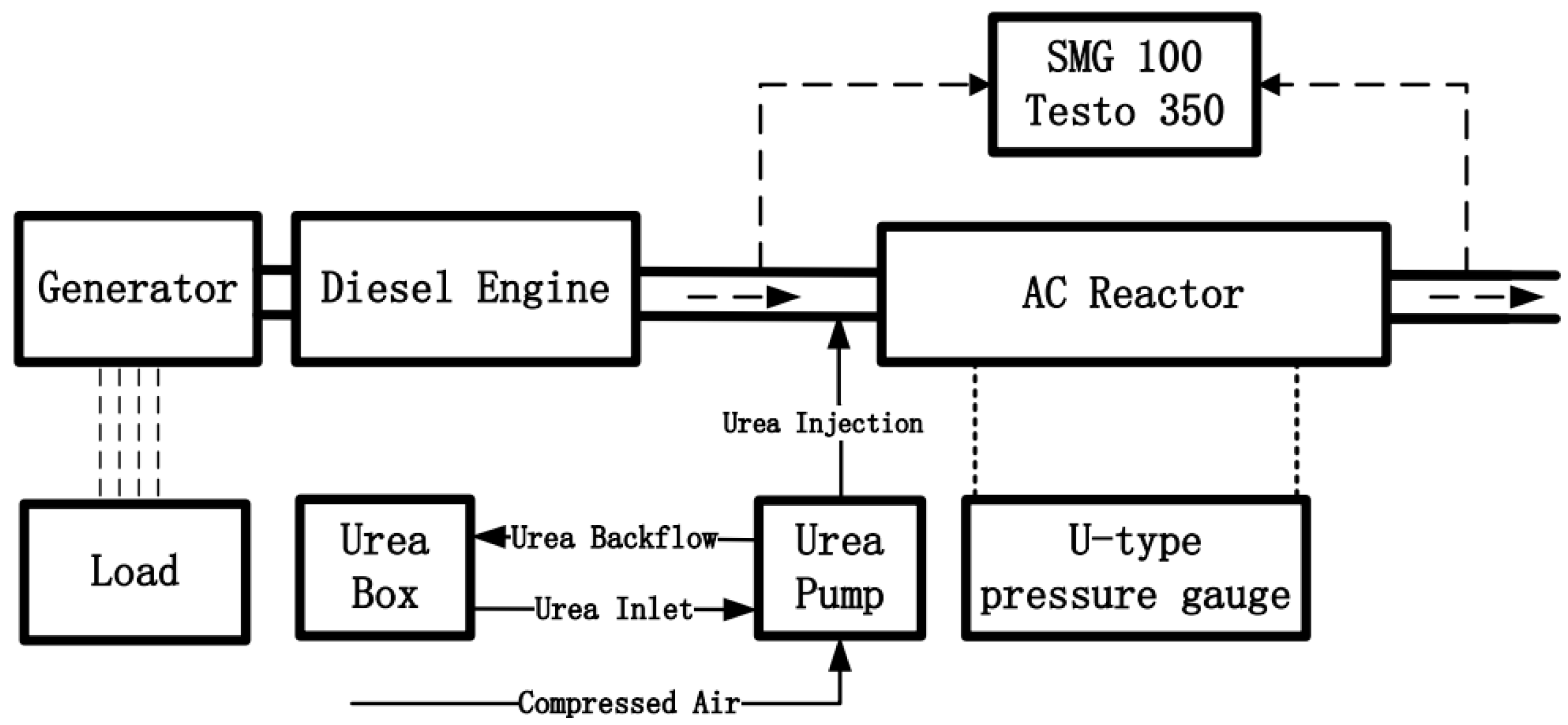
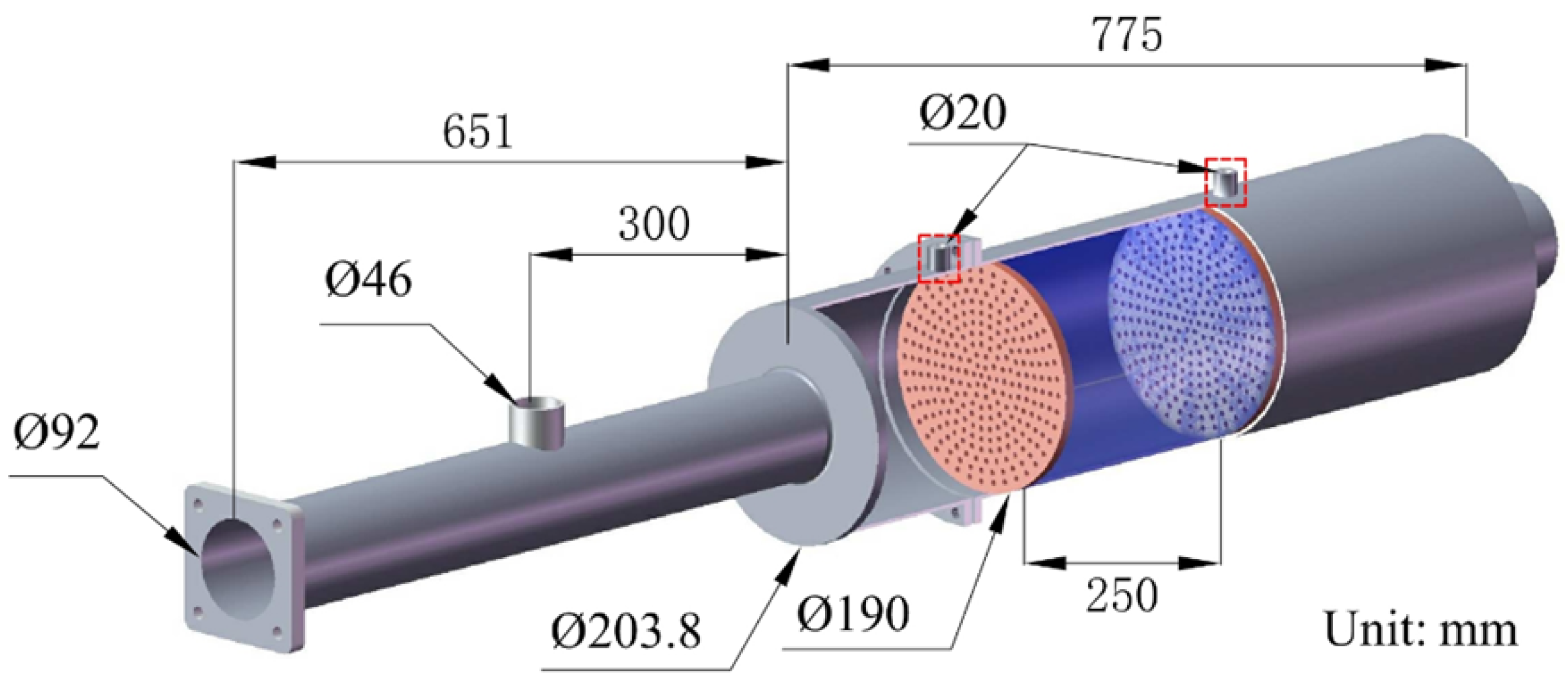
2.1. Experimental System and Material

Figure 1 shows the experimental system. The generator (Shandong Huineng Power Equipment Co., Ltd., 15KVA, Weifang, China) was driven by a diesel engine (Shandong Weichai Power Equipment Co., Ltd., WP2.1D18E2, Weifang, China) at the rated speed of 1500 r/min. Basic parameters and exhaust flow of the diesel engine are shown in Table 1 and Table 2, respectively. No. 5 National Standard diesel oil (sulfur content less than 0.01%) was used in the experiment. The output power of the diesel engine was controlled by an air-cooled electric heating load box. The exhaust gas of the diesel engine passed through the activated carbon reactor. The structure of the AC reactor is shown in Figure 2. The urea nozzle was installed in a hole with a diameter of 46 mm at the front of the reactor, and a grid was installed between the nozzle and the inlet of the reactor to make the urea solution and the exhaust gas mix more uniformly. Two hole-baffles with 250 mm space were installed in the middle of the reactor, and the inside was filled with granular activated carbon. The U-type differential pressure gauge was connected to two holes of 20 mm in diameter. The ammonia for the denitration reaction was hydrolyzed by the 32.5% mass fraction urea solution. The urea metering pump (Emitec, Lohmar, Germany) was air-assisted, which has better atomization effect [23]. The molar ratio of NOx:NH3 was maintained at 1:1. The basic parameters of the columnar activated carbon (Shanxi Xinhua Activated Carbon Factory, Taiyuan, China) are shown in Table 3. The element composition of AC is shown in Table 4. The activated carbon used in each experiment was about 5 kg. The concentration of PM in the exhaust gas was measured by a diesel particle analyzer (SAXON Junkalor GmbH, SMG 100, Dessau, Germany). The concentrations of O2, CO, NO, and NO2 were measured by a flue gas analyzer (Testo company, Testo 350, Freiburg, Germany). In each experiment, the power was increased from the idle load to 15 kW with 3 kW interval. Since the emission of diesel exhaust pollutants was not very constant, in order to reduce the error, the parameters of interest were continuously measured over a period of time after the diesel engine was stable at each power point. The concentrations of the pollutants were the average value at the studied power point. For each power point, the experiment was repeated three times, and the average value of the contaminant concentrations were taken for each power point.

2.2. Data Processing

This paper mainly discusses the removal of CO, PM, and NOx by activated carbon. The removal efficiencies of the three pollutants were calculated by the following Equation:
η = C in C out C in × 100 %
here, η is the removal efficiency of pollutants, %; C in is the pollutant concentration of the reactor inlet, μL/L or mg/Nm3; and C out is the pollutant concentration of the reactor outlet, μL/L or mg/Nm3.
The NOx in diesel exhaust mainly includes NO and NO2, of which NO accounts for more than 90%, and NO2 generally does not exceed 10%. The flue gas analyzer Testo 350 used in this paper can measure the volume fraction of NO and NO2, and the sum of them is the volume fraction of NOx. In order to get the urea flow, it was necessary to first calculate the molar flow of NOx, as shown in Equation (2):
q m o l N O x = q E × v N O x 22.4 × 1000
Here, q m o l N O x is the molar flow of NOx, mol/h; q E is the volume flow of flue gas, Nm3/h; and v N O x is the volume fraction of NOx, μL/L.
To avoid the ammonia slip, the molar ratio of NH3:NOx is generally 1 in practical applications, which gives Equation (3):
q m o l N H 3 = q m o l N O x
here, q m o l N H 3 is the molar flow of NH3, mol/h.
The urea solution generally needs three stages to produce NH3, including evaporation, pyrolysis, and hydrolysis, which can be simplified to Equation (4).
C O ( N H 2 ) 2 + H 2 O 2 N H 3 + C O 2
Therefore, the volume flow of urea with a mass concentration of 32.5% could be expressed as Equation (5).
q V C O ( N H 2 ) 2 = 1000 × q m o l N H 3 × M C O ( N H 2 ) 2 2 × 32.5 % × ρ C O ( N H 2 ) 2
here, q V C O ( N H 2 ) 2 is the volume flow of urea, ml/h; M C O ( N H 2 ) 2 is the molar mass of urea, 60 g/mol; and ρ C O ( N H 2 ) 2 is the density of the urea solution with a mass fraction of 32.5%, taking 1090 g/L.

3. Results and Discussion

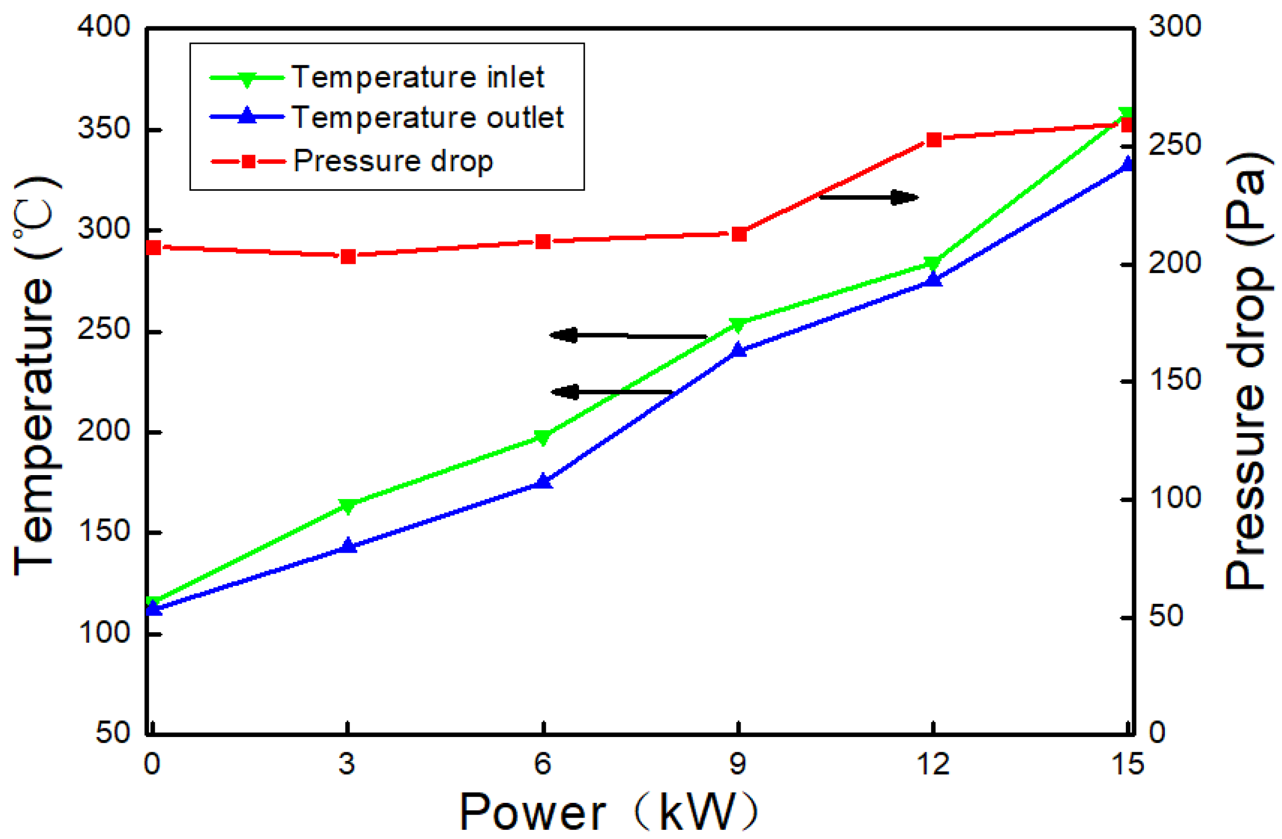
3.1. The Changes of Exhaust Gas Temperature and Pressure Drop

Different engine loads correspond to different sailing conditions of the ship, whether the diesel engine is used as a main engine or a generator. When it is used as the main engine, the engine load is generally below 35% (6 kW or less) under maneuvering sailing, around 45% (6–9 kW) under low-speed sailing, around 75% (about 12 kW) under normal sailing, and 100% (15 kW) under maximum speed sailing. Large-scale ocean-going vessels generally have three or four diesel engine generators. When a diesel engine is used to drive a generator, the typical load is 80% to 90% (about 12 kW), regardless of whether the ship is anchored or sailing. Different exhaust temperatures correspond to different engine loads. Therefore, whether as a main engine or as a power generation diesel engine, the engine load and exhaust gas temperature can correspond to different ship working conditions to a certain extent. The diesel engine used in this paper is a small one and is generally used as a power generation diesel engine for ships. The engine load is commonly about 12 kW.
Figure 3 shows the pressure drop of the AC reactor and exhaust temperature changes at different engine powers. It can be seen from Figure 3 that as the power increased, the exhaust temperature continuously rose. As part of the heat is lost to the environment, the exhaust temperature after passing through the reactor was slightly lower. Moreover, when the power was 6 kW, the exhaust temperature was about 200 °C, and when the power was 15 kW, the diesel engine reached full load, and the exhaust temperature reached 358 °C at the highest. The pressure drop of the reactor was maintained at about 210 Pa in the range of 0–9 kW. When the power further increased, the pressure drop increased significantly, eventually reaching 260 Pa. A possible reason for the pressure increase is that the PM adsorbed on the surface of the activated carbon gradually increased with time, thus causing a certain extent of blockage of the exhaust gas passage, thereby causing an increase in the pressure drop. In practical applications, the activated carbon in the front section of the reactor may be replaced in time according to the exhaust back pressure recommended by the diesel engine manufacturer, or an exhaust fan may be installed after the AC reactor.

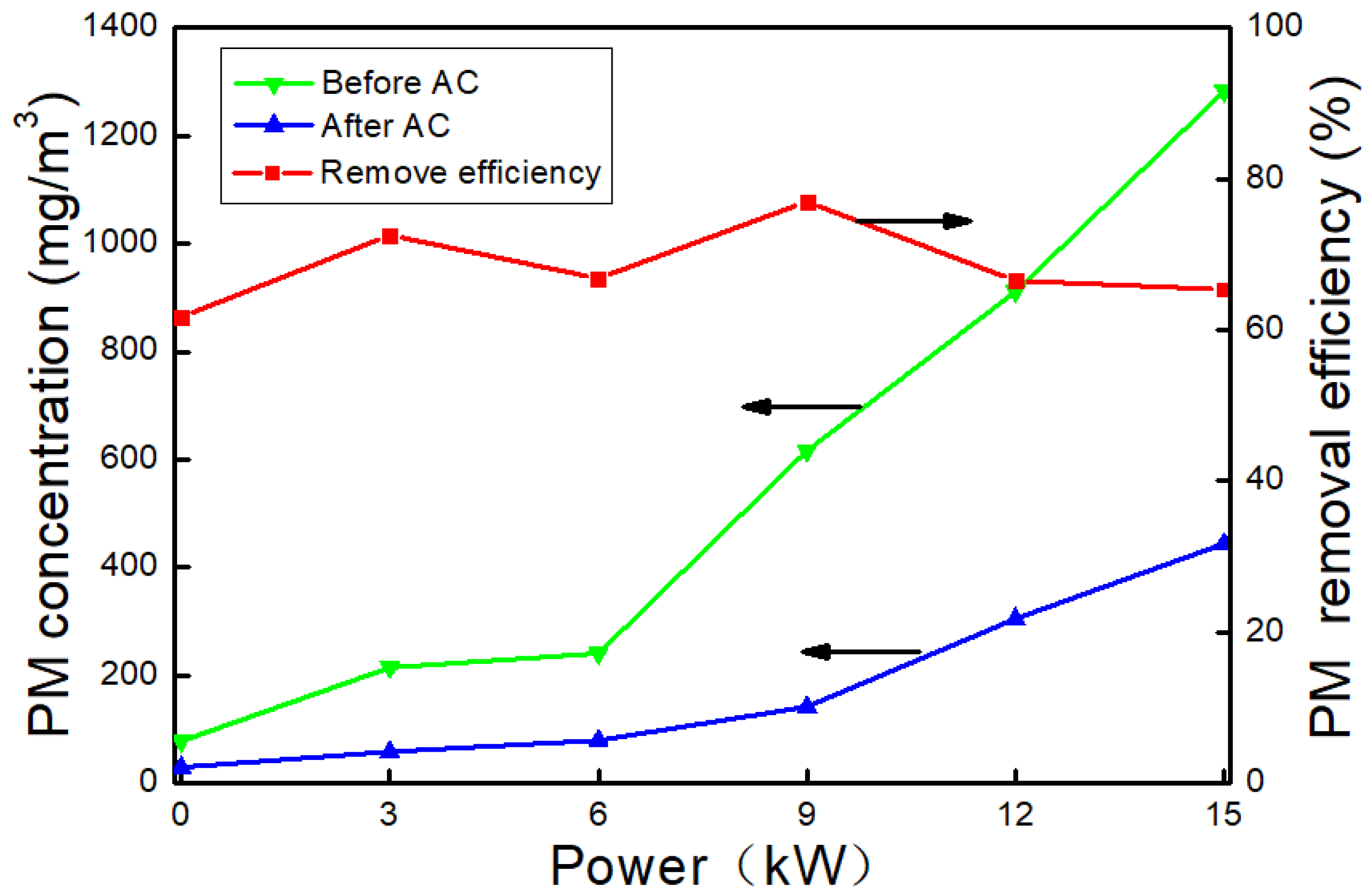
3.2. Effect of AC on PM

Figure 4 shows the changes of PM mass concentration before and after the reactor at different powers and the PM removal efficiency by activated carbon. Since the diesel engine used in this paper used a natural air intake mode, the volume of the intake air did not change with the diesel engine power. However, as the fuel injection amount gradually increased with the engine power, the theoretical air volume for the fuel oil complete combustion increased. This will result in a gradual decrease in the O2 concentration of the exhaust gas as the power increases, and an increase in the PM mass concentration due to incomplete combustion. When the power was lower than 6 kW, the PM concentration of the reactor inlet was lower than 250 mg/Nm3, and with the further increase of power, the mass concentration of PM increased rapidly. When the power reached 15 kW, the mass concentration of PM reached 1282.2 mg/Nm3, at which the removal efficiency of PM was 65.4%. The PM removal efficiencies of the AC reactor were above 60% over the entire power range, and the highest PM removal efficiency achieved at 9 kW reached 77.0%.
To date, there has been no report that activated carbon can catalyze the removal of PM. The main reason for the PM removal in the experiment may be filtration and adsorption by the AC. When the exhaust gas flows through the gap of the granular activated carbon, its speed and direction changes greatly. The PM with a larger particle size gradually decreases and eventually deposits. The PM with smaller particle size will be adsorbed on the surface of the activated carbon. However, it will result in a gradual increase in the pressure drop of the reactor and will affect the denitration ability of the AC. In practical applications, it may be necessary to replace the AC in front of the reactor according to the change of the pressure drop, or to install an exhaust fan after the reactor. The method of diesel particulate filter (DPF) regeneration may be used. For example, activated carbon can be made into honeycomb and regenerated by backwashing.

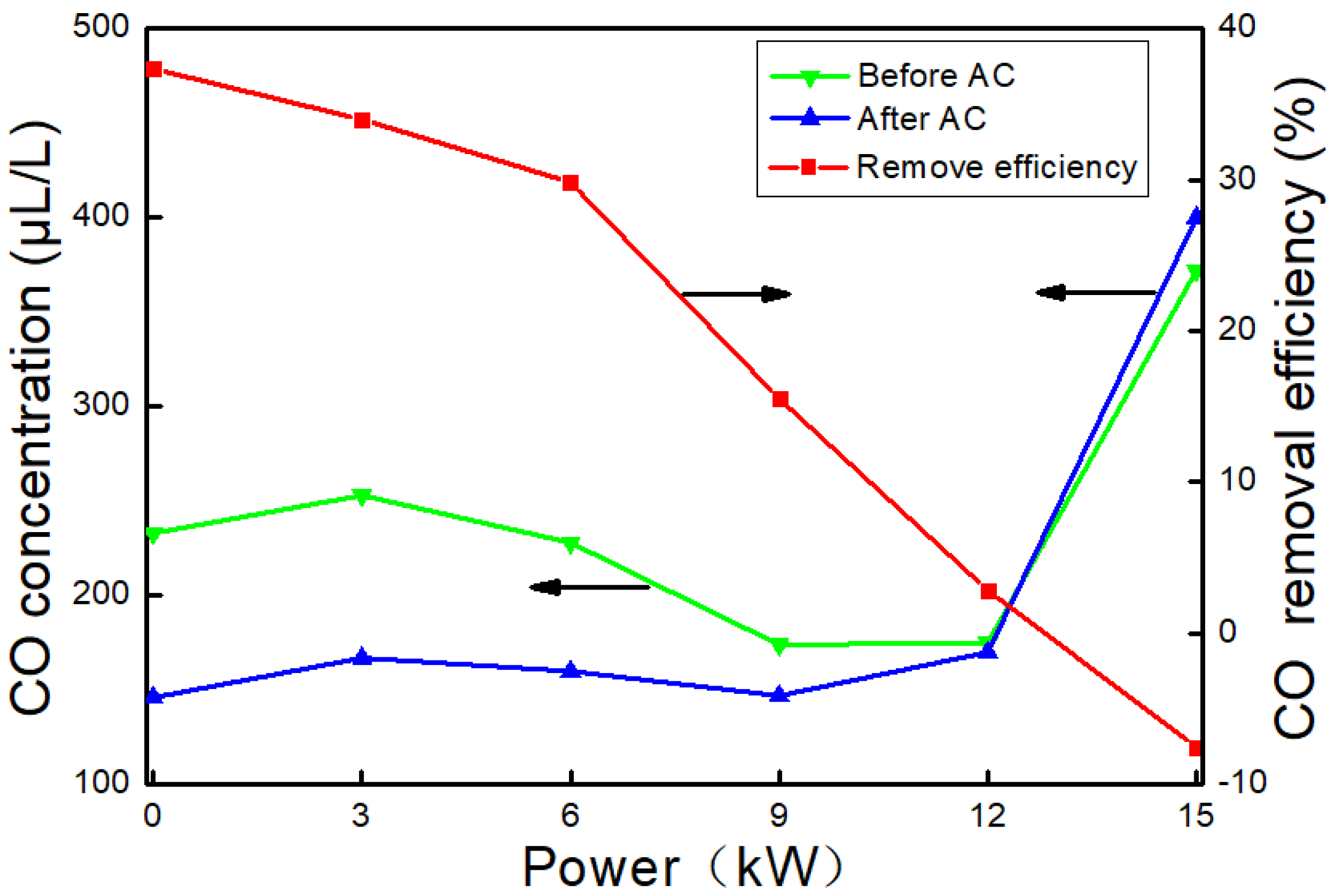
3.3. Effect of AC on CO

The effect of activated carbon on CO at different powers is shown in Figure 5. It can be seen that the running condition of the diesel engine was unstable at low load (0–6 kW), and the CO concentration in the exhaust before entering the reactor was relatively high. The diesel engine reached the best working condition at medium and high load (9 kW and 12 kW), and the CO concentrations also decreased. However, the CO concentration rose sharply at full load (15 kW), which was due to the increase of fuel injection at the full load. The lack of air for natural intake diesel engines results in incomplete fuel combustion. This phenomenon can also be confirmed from the PM change process (Figure 4). CO may act as a reducing agent to participate in denitration reaction to form CO2 under the catalysis of activated carbon. The removal efficiency of CO by activated carbon decreased with the increase of power, and even turned negative when the power was 15 kW. This is because the temperature of the exhaust was low (less than 200 °C) at low power and the adsorption performance of activated carbon is relatively strong. As the power increased, the temperature of the exhaust gas gradually increased, and the adsorption performance of activated carbon gradually decreased. However, the CO removal efficiency turned into −7.5% when the temperature was higher than 300 °C (15 kW). The activated carbon contains some oxygen-containing functional groups such as carboxyl, lactone, and phenolic hydroxyl. The carboxyl and lactone groups are decomposed in the temperature range of 200‒300 °C [24,25], resulting in AC degradation and the increase of CO concentration. In the future, it will be necessary to improve the material and production process to increase the thermal stability of activated carbon.

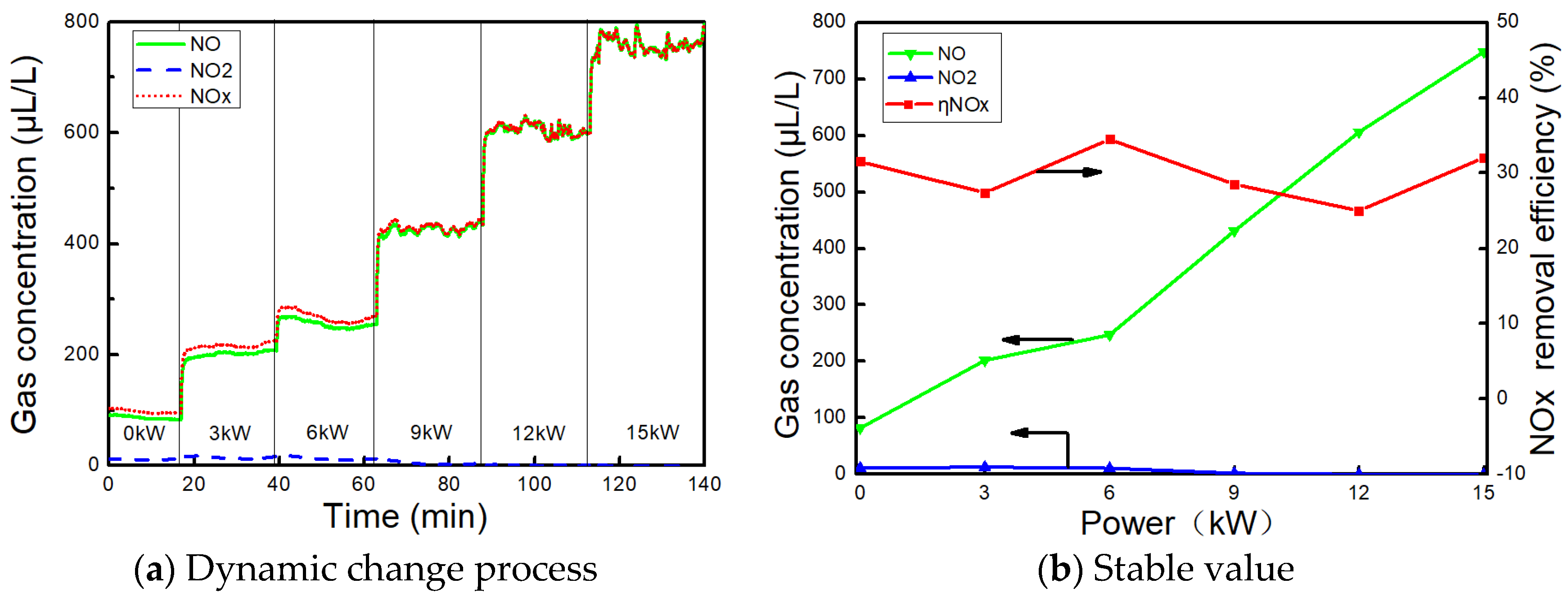
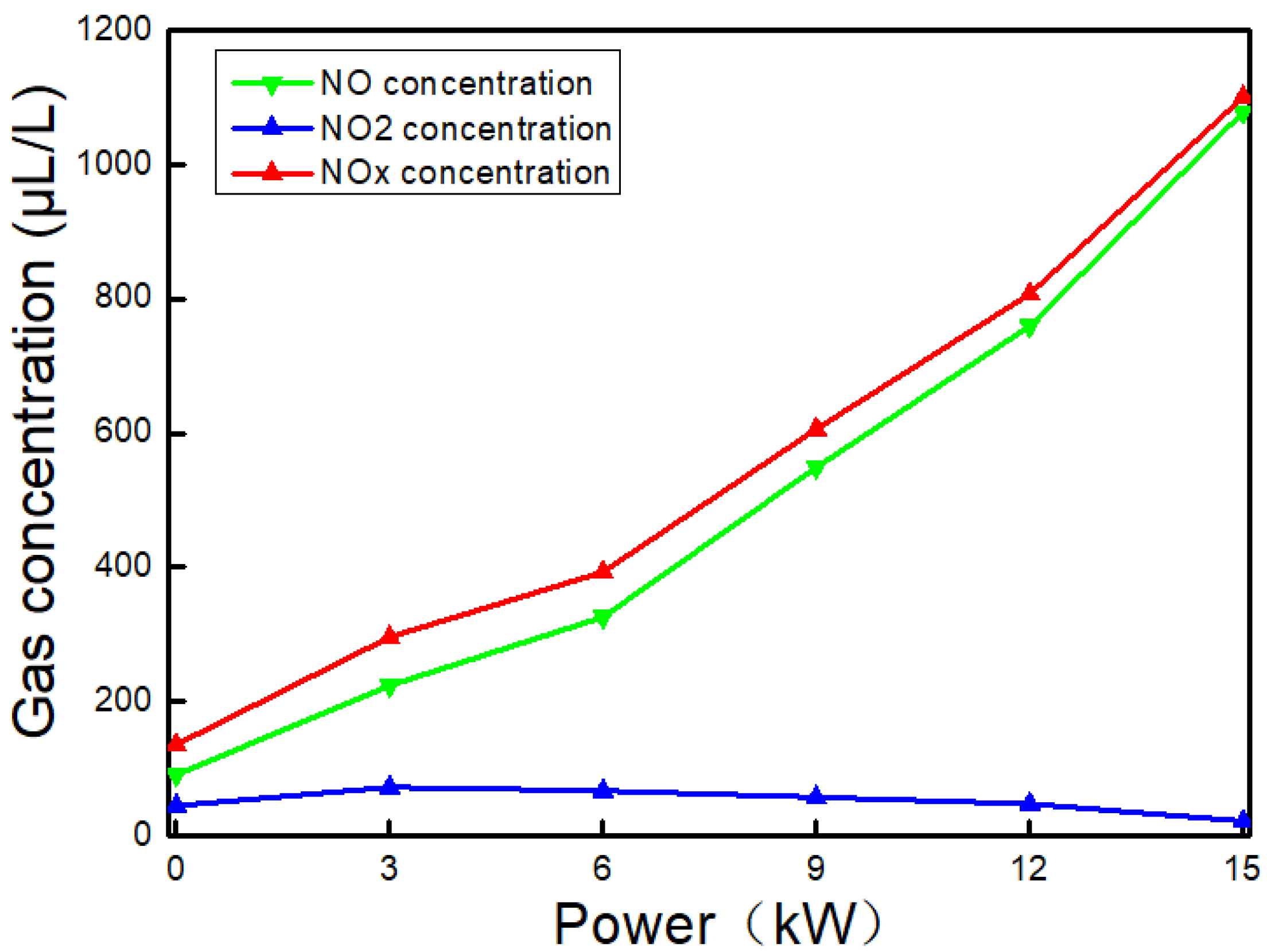
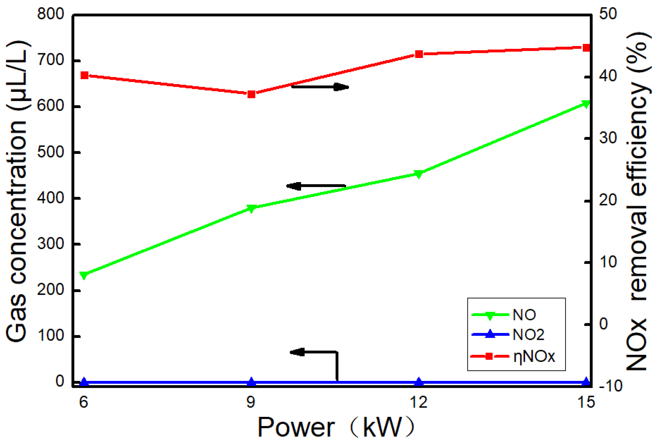
3.4. Effect of AC on NOx

There are three ways to generate NOx, including fuel NOx, prompt NOx, and thermal NOx [26]. Due to the low nitrogen content in diesel fuel, the fuel NOx in diesel exhaust is almost negligible. Prompt NOx can be produced at relatively low temperatures, but the proportion is generally small. Thermal NOx accounts for the highest proportion, and the higher the temperature is, the more NOx will be produced. Figure 6 shows the NOx concentration of the reactor inlet at different powers. It can be seen from Figure 3 that the temperature of the exhaust gas increased with the power. Therefore, the concentration of NO gradually increased with the power, and the NO concentration at 15 kW was up to 1079 μL/L, as shown in Figure 6. It is generally believed that NO can be rapidly converted to NO2 in the flame zone, and the generated NO2 can be preserved after being mixed with a cold gas. Therefore, the ratio of NO2:NO was higher in the low-load operation of the diesel engine. It can be seen from Figure 6 that the concentration of NO2 was high at a low load and the highest was 72.2 μL/L (3 kW), and then the concentration of NO2 gradually decreased with the power. The NOx concentration in the diesel exhaust at 15 kW was up to 1101 μL/L.
Figure 7 shows the change of NOx concentration at the outlet of the AC reactor when urea is not sprayed. The dynamic change process and the outlet NOx stability value are shown in Figure 7a,b, respectively. During the experiment process, the diesel engine power gradually increased from 0 kW to 15 kW, and each power point was kept for a certain period of time to ensure that the outlet NOx concentration was basically stable. It can be seen from Figure 7 that the NO2 concentration of the outlet was very low at low power (0–6 kW), and close to zero at medium and high power (9–15 kW), indicating that the NO2 removal performance of activated carbon was good. The NO concentration increased gradually with the power in the entire power range. There was a certain degree of NO reduction compared to the inlet NO concentration. The denitration efficiency was 34.5% at 6 kW. The AC reacted with O2 in the exhaust to form the oxygen-containing functional groups, Cf. These oxygen-containing functional groups are the main active sites of AC, and are closely related to the adsorption and catalytic properties of AC [27,28,29,30]. AC can be both a catalyst and a reducing agent in the denitration process. In addition, the reducing CO and CxHy in the exhaust also act as a reducing agent at the surface active sites of the AC. The possible reactions include Equations (6)–(9).
C + O 2 C f
C O + N O x C f N 2 + C O 2
C x H y + N O x + O 2 C f N 2 + H 2 O + C O 2
C x H y + N O x + O 2 C f N 2 + H 2 O + C O
Figure 8 shows the change of NOx concentration at the outlet of the AC reactor when urea was injected. Since the urea hydrolysis temperature was above 150 °C [31,32] and the exhaust gas temperature of the diesel engine used in this experiment was below 150 °C when the power is lower than 3 kW (shown as Figure 3), no urea was injected into the reactor below 3 kW. According to the calculation method given in Section 2.2, the injection amounts of urea at different powers in the range of 6 to 9 kW are shown in Table 5. After the injection of urea, it can be seen from Figure 8 that the NO2 concentration at the outlet was essentially zero, while the NO concentration increased with the power. The NOx concentration was reduced to some extent, and the denitration efficiency was 44.8% at 15 kW.
At present, the commercial denitration catalyst generally had a high denitration efficiency at temperatures higher than 200 °C. The exhaust gas temperature was low at low power and urea is generally not sprayed, resulting in a poor denitration effect at low power. Diesel engines usually run in a low-power state when ships enter or depart from ports. At this time, exhaust emissions mainly occur in the ports. The atmospheric pollution caused by this process has a serious impact on the environment. It is beneficial to utilize the better adsorption ability of AC at low temperatures to initially adsorb and store NOx. When the ship is at cruising speed, the exhaust gas temperature rises with the power. Excess urea solution can be sprayed for denitration reaction when the temperature is higher than the hydrolysis temperature of urea. One way to improve the denitration efficiency is to modify the activated carbon [33,34] or load with other metal oxides [35,36]. In that case, activated carbon could serve as a practical solution for marine diesel engine exhaust denitration.

4. Conclusions

Based on the above experiments on the removal ability of coal-based activated carbon under different conditions, this paper mainly draws the following conclusions:
(1)
The removal of PM was mainly by the adsorption and filtration of activated carbon. The PM removal efficiency of the AC reactor was above 60% in the entire power range, and the highest PM removal efficiency was 77% at 9 kW. However, the pressure drop of the reactor gradually increased with the running time. In the future, a fan can be installed after the reactor, or the granular AC can be made into a honeycomb structure and the regeneration method of DPF backwashing can be used to prolong the service time.
(2)
CO can be used as a reducing agent to participate in the denitration reaction under the catalytic action of AC. The removal of CO depends on the adsorption of AC. Since the temperature of the exhaust gas gradually increases with the power, the AC may have a certain degeneration. It is necessary to improve the thermal stability of AC by material and production process for practical purposes.
(3)
The NOx concentration of the exhaust gas gradually increases with the power. The denitration ability of AC was poor when urea is not sprayed, and the denitration efficiency was 34.5% at 6 kW. When urea was sprayed, NH3 was generated by urea hydrolysis. With NH3 as a reducing agent, the NO2 removal efficiency was close to 100%, and the highest denitration efficiency was 44.8% at 15 kW. Overall, the denitration efficiency of AC was still lower than other denitration catalysts, and it needs to be modified or loaded with other metal oxides to improve its denitration efficiency.

Author Contributions

Conceptualization, Z.W., J.Z. and Y.J.; Data curation, H.K. and L.C.; Formal analysis, Z.W. and H.K.; Investigation, Z.W., H.K. and L.C.; Resources, Y.J.; Writing–original draft, Z.W.; Writing–review & editing, J.Z. and Y.J.

Funding

This research was supported by the National Natural Science Foundation of China (51876019, 51579026), the Program for Liaoning Innovative talents in University (LR2017048), the Program for High-Level Talent Training in Transportation Industry of China, and the Program of Liaoning Revitalization Talents (XLYC1807117), and the Fundamental Research Funds for the Central Universities of China (3132019331).

Conflicts of Interest

The authors declare no conflict of interest.

References

  1. Chen, G.J.; Liu, Z.M.; Liu, T.T.; Su, S.H.; Yuan, G.J.; Cao, Y.J. Research on emission control of marine diesel engine. Proc. Adv. Mater. Res. 2012, 430, 1198–1202. [Google Scholar] [CrossRef]
  2. Yoo, D.-H.; Nitta, Y.; Ikame, M.; Hayashi, M.; Fujita, H.; Lim, J.-k. Exhaust characteristics of nitrous oxide from marine engine. In Proceedings of the 2012 Oceans-Yeosu, Yeosu, Korea, 21–24 May 2012; pp. 1–7. [Google Scholar]
  3. Zhu, Y.; Tang, X.; Li, T.; Ji, Y.; Liu, Q.; Guo, L.; Zhao, J. Shipboard trials of magnesium-based exhaust gas cleaning system. Ocean Eng. 2016, 128, 124–131. [Google Scholar] [CrossRef]
  4. International Maritime Organization (IMO). IMO Sets 2020 Date for Ships to Comply with Low Sulphur Fuel Oil Requirement. Available online: http://www.imo.org/en/MediaCentre/PressBriefings/Pages/MEPC-70-2020sulphur.aspxx (accessed on 2 July 2019).
  5. MAN Diesel & Turbo. MAN Diesel & Turbo Delivers World’s First IMO-Certified Two-Stroke Engine with Tier III NOx Control, Exhaust Gas Recirculation Systems. Available online: https://www.corporate.man.eu/en/press-and-media/presscenter/MAN-Diesel-and-Turbo-Delivers-World_s-First-IMO-Certified-Two-Stroke-Engine-with-Tier-III-NOx-Control_-Exhaust-Gas-Recirculation-Systems-241408.html (accessed on 2 July 2019).
  6. Brandenberger, S.; Kröcher, O.; Tissler, A.; Althoff, R. The determination of the activities of different iron species in Fe-ZSM-5 for SCR of NO by NH3. Appl. Catal. B Environ. 2010, 95, 348–357. [Google Scholar] [CrossRef]
  7. Hsieh, M.-F.; Wang, J. Development and experimental studies of a control-oriented SCR model for a two-catalyst urea-SCR system. Control Eng. Pract. 2011, 19, 409–422. [Google Scholar] [CrossRef]
  8. Colombo, M.; Nova, I.; Tronconi, E. Detailed kinetic modeling of the NH3–NO/NO2 SCR reactions over a commercial Cu-zeolite catalyst for Diesel exhausts after treatment. Catal. Today 2012, 197, 243–255. [Google Scholar] [CrossRef]
  9. Sjövall, H.; Olsson, L.; Fridell, E.; Blint, R.J. Selective catalytic reduction of NOx with NH3 over Cu-ZSM-5—The effect of changing the gas composition. Appl. Catal. B Environ. 2006, 64, 180–188. [Google Scholar] [CrossRef]
  10. Zhang, W.; Rabiei, S.; Bagreev, A.; Zhuang, M.; Rasouli, F. Study of NO adsorption on activated carbons. Appl. Catal. B Environ. 2008, 83, 63–71. [Google Scholar] [CrossRef]
  11. Gao, X.; Liu, S.; Zhang, Y.; Luo, Z.; Ni, M.; Cen, K. Adsorption and reduction of NO2 over activated carbon at low temperature. Fuel Process. Technol. 2011, 92, 139–146. [Google Scholar] [CrossRef]
  12. Ghouma, I.; Jeguirim, M.; Dorge, S.; Limousy, L.; Ghimbeu, C.M.; Ouederni, A. Activated carbon prepared by physical activation of olive stones for the removal of NO2 at ambient temperature. C. R. Chim. 2015, 18, 63–74. [Google Scholar] [CrossRef]
  13. Huang, Z.; Hou, Y.; Zhu, Z.; Liu, Z. Study on the NO reduction by NH3 on a SO42−/AC catalyst at low temperature. Catal. Commun. 2014, 50, 83–86. [Google Scholar] [CrossRef]
  14. Zhu, L.; Huang, B.; Wang, W.; Wei, Z.; Ye, D. Low-temperature SCR of NO with NH3 over CeO2 supported on modified activated carbon fibers. Catal. Commun. 2011, 12, 394–398. [Google Scholar] [CrossRef]
  15. Figueiredo, J.L.; Pereira, M.F.R. The role of surface chemistry in catalysis with carbons. Catal. Today 2010, 150, 2–7. [Google Scholar] [CrossRef]
  16. Izquierdo, M.T.; Rubio, B.; Mayoral, C.; Andrés, J.M. Low cost coal-based carbons for combined SO2 and NO removal from exhaust gas. Fuel 2003, 82, 147–151. [Google Scholar] [CrossRef]
  17. Ding, S.; Li, Y.; Zhu, T.; Guo, Y. Regeneration performance and carbon consumption of semi-coke and activated coke for SO2 and NO removal. J. Environ. Sci. 2015, 34, 37–43. [Google Scholar] [CrossRef]
  18. Ding, J.L.; Zhao, Y.Q.; Zhang, Y.F.; Fu, Y.L. Influence of Non-Pitch Based Activated Carbon on Flue Gas Desulfurization. Proc. Appl. Mech. Mater. 2013, 316–317, 1055–1058. [Google Scholar] [CrossRef]
  19. Mochida, I.; Korai, Y.; Shirahama, M.; Kawano, S.; Hada, T.; Seo, Y.; Yoshikawa, M.; Yasutake, A. Removal of SOx and NOx over activated carbon fibers. Carbon 2000, 38, 227–239. [Google Scholar] [CrossRef]
  20. Sousa, J.P.; Pereira, M.F.; Figueiredo, J.L. Modified activated carbon as catalyst for NO oxidation. Fuel Process. Technol. 2013, 106, 727–733. [Google Scholar] [CrossRef]
  21. Wang, H.; Wang, S.; Duan, Y.; Li, Y.-N.; Xue, Y.; Ying, Z. Activated carbon for capturing Hg in flue gas under O2/CO2 combustion conditions. Part 1: Experimental and kinetic study. Energy Fuels 2018, 32, 1900–1906. [Google Scholar] [CrossRef]
  22. Zhou, Q.; Duan, Y.; Chen, M.; Liu, M.; Lu, P. Studies on mercury adsorption species and equilibrium on activated carbon surface. Energy Fuels 2017, 31, 14211–14218. [Google Scholar] [CrossRef]
  23. Zhao, Y.; Hua, L.; Hu, J.; Tang, T.; Shuai, S.; Wang, J. Experimental study of urea solution spray characteristics in SCR system of diesel engine. Chin. Intern. Combust. Engine Eng. 2012, 33, 22–27. [Google Scholar]
  24. Zhuang, Q.; Kyotani, T.; Tomita, A. The change of TPD pattern of O2-gasified carbon upon air exposure. Carbon 1994, 32, 539–540. [Google Scholar] [CrossRef]
  25. Zielke, U.; Hüttinger, K.; Hoffman, W. Surface-oxidized carbon fibers: I. Surface structure and chemistry. Carbon 1996, 34, 983–998. [Google Scholar] [CrossRef]
  26. Liu, Y. Study on Removal of Particles and NOx from Diesel Engines by Application of POC and SCR Technologies; Shandong University: Jinan, China, 2015. [Google Scholar]
  27. Yahya, M.A.; Al-Qodah, Z.; Ngah, C.Z. Agricultural bio-waste materials as potential sustainable precursors used for activated carbon production: A review. Renew. Sustain. Energy Rev. 2015, 46, 218–235. [Google Scholar] [CrossRef]
  28. Wang, Z.; Kuang, H.; Zhang, J.; Chu, L.; Ji, Y. Nitrogen Oxide Removal by Coal-Based Activated Carbon for a Marine Diesel Engine. Appl. Sci. 2019, 9, 1656. [Google Scholar] [CrossRef]
  29. Li, Y.; Duan, Y.; Wang, H.; Zhao, S.; Chen, M.; Liu, M.; Wei, H. Effects of acidic gases on mercury adsorption by activated carbon in simulated oxy-fuel combustion flue gas. Energy Fuels 2017, 31, 9745–9751. [Google Scholar] [CrossRef]
  30. Ghouma, I.; Jeguirim, M.; Sager, U.; Limousy, L.; Bennici, S.; Däuber, E.; Asbach, C.; Ligotski, R.; Schmidt, F.; Ouederni, A. The potential of activated carbon made of agro-industrial residues in NOx immissions abatement. Energies 2017, 10, 1508. [Google Scholar] [CrossRef]
  31. Lv, H.; Yang, W.; Zhou, J.; Zhang, M.; Li, F. Investigation on thermal decomposition characteristics of urea solution under high temperature. Proc. CSEE 2010, 30, 35–40. [Google Scholar]
  32. Zhang, X.; Zhang, B.; Lu, X.; Xiang, X.; Xu, H. Crafts design and experimental study of urea hydrolysis to ammonia in thermal power plant. Proc. CSEE 2016, 36, 2452–2458. [Google Scholar]
  33. Fu, Y.; Zhang, Y.; Li, G.; Zhang, J.; Guo, Y. NO removal activity and surface characterization of activated carbon with oxidation modification. J. Energy Inst. 2017, 90, 813–823. [Google Scholar] [CrossRef]
  34. Samojeden, B.; Grzybek, T. The influence of the promotion of N-modified activated carbon with iron on NO removal by NH3-SCR (Selective catalytic reduction). Energy 2016, 116, 1484–1491. [Google Scholar] [CrossRef]
  35. Shu, Y.; Zhang, F.; Wang, F.; Wang, H. Catalytic reduction of NOx by biomass-derived activated carbon supported metals. Chin. J. Chem. Eng. 2018, 26, 2077–2083. [Google Scholar] [CrossRef]
  36. Wang, M.; Liu, H.; Huang, Z.-H.; Kang, F. Activated carbon fibers loaded with MnO2 for removing NO at room temperature. Chem. Eng. J. 2014, 256, 101–106. [Google Scholar] [CrossRef]
Figure 1. Experimental system schematic.
Applsci 09 03175 g001
Figure 2. Schematic of the activated carbon (AC) reactor.
Applsci 09 03175 g002
Figure 3. Gas temperature and pressure drop changes.
Applsci 09 03175 g003
Figure 4. Effect on particulate matter (PM) concentration by AC reactor.
Applsci 09 03175 g004
Figure 5. Effect of AC on CO.
Applsci 09 03175 g005
Figure 6. NOx concentration of AC reactor inlet.
Applsci 09 03175 g006
Figure 7. NOx concentration of AC reactor outlet (without urea). (a) Dynamic change process; (b) stable value.
Applsci 09 03175 g007
Figure 8. NOx concentration of AC reactor outlet (with urea).
Applsci 09 03175 g008
Table 1. Parameters of diesel engine.
CylinderBore (mm)Stroke (mm)Compression RatioDisplacement (L)Air Inlet MethodPower (kW)Rated Speed (r/min)
4859218:12.09Natural17.51500
Table 2. Exhaust flow at different generated power levels.
Power (kW)03691215
Exhaust flow (Nm3/h)119.3105.598.389.988.082.8
Table 3. Parameters of activated carbon.
Diameter (mm)Length (mm)Iodine Value (mg/g)Fire Point (°C)Bulk Density (g/L)SBET (m2/g)Vtotal (cm3/g)Vmic (cm3/g) D ¯ ( nm )
105.6~11.2371456650326.4910.2000.1122.454
Note: SBET: BET surface area; Vtotal: total pore volume; Vmic: micropore volume D ¯ : average pore diameter.
Table 4. Element composition of AC.
ElementCOSiAlCa
Mass percentage (%)48.0720.648.835.756.58
Atomic Percentage (%)64.2620.715.053.422.64
Table 5. Urea volume flow at different powers (unit: mL/h).
Power (kW)691215
Urea Flow (mL/h)146206269345

