Abstract
This paper deals with the numerical calculation method of deflection deformation of rice stalks. Due to large deflection of rice stalks caused by reel operation, it is improper to adopt the conventional formula that is usually used in small deflection calculation to fit rice stalk deformation curves. Therefore, a large deflection calculation formula in combination with Simpson’s formula was utilized to compute flexural rigidity (EI) and to fit curves. The experiments were conducted under different loads (0.03, 0.04, 0.05, 0.06, and 0.07 N) on a self-established deflection testing rig to verify this method. As a result, the measured results corresponded considerably to ones predicted by this method; furthermore, the flexural rigidity was maintained at a stable level under different loads. This study can provide the basis for establishing a complete deformation model of rice plant and can also be applied in deflection calculation of other stalk crops.
1. Introduction
Rice is the staple crop and plays an important role in China’s agricultural production. According to statistical data of 2016, released by the Editorial Board of the Year Book of Agricultural Mechanization in China, China’s rice yield reached 207,075.1 kt, the sown area 30,178.24 khm2, and the mechanized harvesting rate was 87.11%. At present, many colleges, universities, and research institutions around the world focus on the intellectualization of rice harvesters; that is, achievement of automatic sensing and adjustment, and the adaptive control of different components on harvesters by utilizing different kinds of sensors. However, little work about the interaction between rice plant and harvesters has been done [1,2,3,4,5,6]. The deflection deformation of the rice plant, caused by reel, is important to determine a reasonable cutting height. For example, it is usually adopted by harvester operators to lift the header to a higher position during regular rice harvesting, to lower energy consumption in the processes of cutting, threshing, and cleaning. It is also required to harvest the main season of ratoon rice at a specific height to ensure the yield of ratoon season. In short, a proper cutting position could optimize the power configuration of harvesters and satisfy the requirement of special crop. As no accurate calculation methods exist for rice stalk deformation, the cutting height is simply decided empirically by operators. Thus, a simple and efficient calculation method of the deflection is needed.
Parameters indispensable in the deflection calculation of crop stalks are Young’s modulus and the cross-section moment of inertia, and many experiments have been conducted to acquire the parameters. Xiang et al. (2007) indicated that the elastic modulus of rice stalks increased as the stalk grew more mature, and the elastic modulus of the different internodes in the same variety varied, with the order being internode 2 > internode 3 > internode 4 [7]. A bending model of rice stalks based on formula deduction and empirical data was deduced in previous papers [8,9]. Hirai et al. (2004) established a reel model in the lab to test the displacement response of rice and wheat stalks at the condition of quasi-state loading [10]. It was indicated that the rape stem of the elastic modulus increases with the reduction of moisture content of stem [11]. İnce et al. (2005) reported that the modulus of elasticity of sunflower stalks decreased with increases in moisture content and stalk diameter [12]. Esehaghbeygi et al. (2009) revealed that moisture content had a significant effect (p < 0.05) on the modulus of elasticity of wheat stem of Alvand variety [13]. Chattopadhyay and Pandey (1999) found that the modulus of elasticity of sorghum stalk in bending did not change significantly (p < 0.05) when the rate of loading was increased from 10 to 100 mm/min [14].
Accurate calculation of crop stalk deformation needs efficient algorithms which can be operated on an upper computer. Yu et al. (2013) established an accurate lodging resistance model by applying an added approximate equation of deflection curve and principle of resident potential energy [15]. Inoue et al. (1998) also introduced the large deflection formula into the deflection calculation, but the calculation process was complicated and time-consuming [16]. Jiang et al. (1998) deduced the formula for cantilever beam with variational cross-section subject to pure bending in large deflection [17]. Chen (2003) used the boundary integral method to solve the problem of bending of the heavy camber cantilever beam [18]. Yang and Wang (1998) introduced the numerical integral method to solve the deformation of large deflection bending of the cantilever beam [19].
The primary objective of this study was to develop an easy, quick, and accurate numerical calculation method to achieve the calculation of the deflection curve of rice stalks to provide a basis for establishing a complete rice plant deformation model. This method can not only be applied in rice harvesting, but stalk crops like wheat, oilseed rape, sunflower, among others. While this study is only concerned with the calculation of rice stalks below the acting point of reel, more research should be conducted to realize the calculation of whole rice plant.
2. Materials and Methods
2.1. Force Analysis of Rice Stalk
An assumption that the stalk between the acting point of reel and the ground connection point is bent elastically under the action of the reel was made. As shown in the Figure 1, the rice plant is deformed under the action of the reel, and the acting force F is directed normal to the curvature of the rice stalk. The force F could be decomposed into a horizontal force Fh and a tangential force Fτ; the Fτ could be neglected due to little observed deformation along the tangential direction [9]. Thus, to simplify the calculation, only the acting force Fh was considered in this study. At the same time, to eliminate the influence of the ear, leaves, and extra stalk, only stalk AO between the acting point and the ground connection point was retained. As shown in Figure 1, Stalk AO was deformed to A′O under the action of F, its flexural rigidity was EI, and E and I were the elastic modulus and the cross-section moment of inertia of the stalk, respectively. To calculate the deflection of the stalk, a Cartesian coordinate system was established, which had ordinate Y as the independent variable, and Δ as the dependent variable.
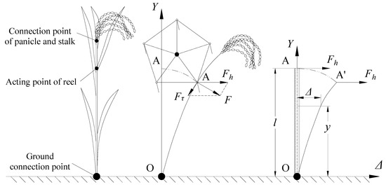
Figure 1.
Analysis of rice stalk and the establishment of coordinate system. l, length of stem AO; F, the horizontal force acting on the stalk AO.
2.2. Conventional Calculation Formula
The conventional calculation formula used in micro-deformation field is [17]
where M is the sum of bending moment at point A, N·mm; EI is the flexural rigidity of stalk, N·mm2.
EI can be obtained by integrating twice at both sides of Equation (1):
where Δ is the deflection of point A, mm; F is the horizontal force acted on the stalk, N; l is the length of the stalk, mm.
Equation (2) is the formula that is usually used to calculate the flexural rigidity of cantilever beams. EI can be solved by substituting known F, l, and Δ into Equation (2), and the deflection of the any point of the stalk can be calculated by substituting those parameters into Equation (3).
2.3. Large Deflection Calculation Formula
Equations (1)–(3) can only be applied to micro-deformation fields. However, to compute the large deflection of the rice stalk, which is commonly 100–200 mm [16], this paper introduced the large deflection formula:
By integrating Equation (4), Equation (5) could be obtained:
Equation (5) could be integrated again to calculate the deflection curve of rice stalks. Since Equation (5) involves elliptic integration, it is difficult to obtain the analytical solution, so a numerical calculation method was adopted to solve the equation. In this paper, the fourth-order Runge–Kutta method [20] was adopted for calculation.
2.4. Calculation Method of Flexural Rigidity
In order to solve the calculation of Equation (5), it is indispensable to acquire the value of EI. Considering the large deflection of the stalk, and to avoid the calculation of elliptical integration, Simpson’s formula was used to compute the value of EI. The force analysis is shown in Figure 2. Stalk AO is deformed to A′O under the action of the horizontal force F, the longitudinal displacement, and the deflection of point A are δA, ΔA, respectively. The deformed stalk is then divided into eight equal segments along the longitudinal direction in order to apply Simpson’s formula [21] to the calculation.
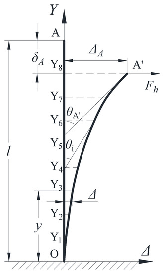
Figure 2.
Deflection model of stalk AO. δA, vertical displacement of point A, mm; ΔA deflection of point A, (mm); l, length of the stalk AO, mm; θA′, angle between the tangent line of point A and the axis Y, (°); θi, angle between A′Yi and the axis Y, (°).
Equation (4) can be derived as
and the sum of the bending moment of point y is
The following equation can be obtained by integrating Equation (6) with Equation (7), and substituted into
According to the boundary conditions that y = l − δA and θ = θA′, Equation (9) could be obtained:
On the basis of Equation (9), the vertical displacement of point A could be acquired:
where S is the length of arc A′O, mm.
where ΔA is the deflection of point A, mm.
Simpson’s formula can be presented as
In order to apply Equation (13), A′O is divided into eight segments, that is, the area between [0, lA − δA] is partitioned into eight equal segments, where each length of the segment is h = (l − δA)/8. Then Equations (11) and (12) could be modified as
where Sinθ is defined by Equation (8). Considering the y value of point i:
Combine Equations (9), (16) and (17), Sinθi can be presented as:
EI could be solved by substituting Equations (10) and (17) into Equations (14) and (15), and the deflection curve of stalk AO can be calculated by inputting the value of EI into Equation (5).
2.5. Experiment Material
Rice, variety Fengliangyouxiang 1, planted in Sanhu Farm, Jingzhou, Hubei province of China, was used as the test material. Rice stem samples were obtained from the plots (location: 30.216289° N, 112.570919° W) having uniform growth, and were randomly chosen and manually cut by a sickle at the ground level. The experiments were conducted at Key Laboratory of Modern Agricultural Equipment and Technology, Ministry of Education, Jiangsu University, Zhenjiang, China during the year 2018.
In this paper, 600 mm stalks were used, and they were evenly marked with sixteen points in order to record the actual curves of stalk deformation on the coordinate board.
2.6. Bending Experiment in Deflection Testing Rig
The diagram of the rig is shown in Figure 3. The rig consisted of a hand-operated support, a digital force meter (type: ZP-10, capacity: 10 N, resolution: 0.001 N, Fuma Electronic Equipment Co. LTD, Dongguan city, China), an adjustable table, a clamp, and a coordinate board.
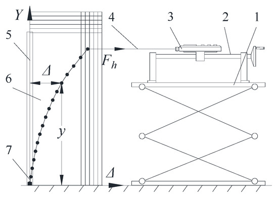
Figure 3.
Testing rig: (1) adjustable table, (2) hand-operated support, (3) digital force meter, (4) rope, (5) stalk, (6) coordinate board, (7) clamp.
Each stalk prepared was held by the clamp at the bottom, and an inelastic rope was fastened to the top of stalk with its other end connected to the force meter. Then, the handle of the hand-operated supporter should be slowly rotated to exert a certain force, which can be seen on the digital force meter, on the stalk. It should be mentioned that the adjustable table should be adjusted anytime during the experiment to keep the rope horizontal. At last, the positions of the 16 points should be noted on the coordinate board to record the actual curve of deflection. Each stalk was continuously loaded for five times, with the horizontal force being 0.03, 0.04, 0.05, 0.06, and 0.07 N, consecutively.
3. Results
The deflection curves of the stalk with the ear, leaves, and extra stalk removed, which was separately loaded with 0.03, 0.04, 0.05, 0.06, and 0.07 N, are shown in the Figure 4. It was clear that higher the load, the larger the deflection. A one-way analysis of variance (ANOVA) test was conducted, the result indicating that load was significantly related to deflection (p < 0.05).
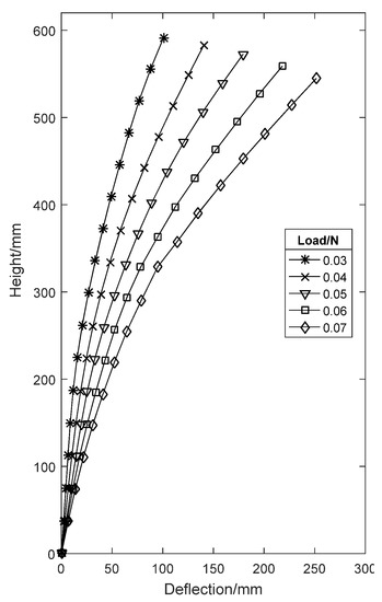
Figure 4.
Rice stalk (measured values).
The deflection values of the stalk, corresponding to the deflection of point A, were then used to calculate EI by substituting them into Equations (2), (14), and (15). The results were shown in Figure 5. It was obvious that the EI values were basically consistent by using Equations (14) and (15). A one-way ANOVA test was also conducted, the result indicating that differing deflection had no significant influence on flexural rigidity (p < 0.05), while the values of Equation (2) differed widely when the deflection increased. The experiment validated the appropriateness of Simpson’s formula for the calculation the flexural rigidity. On the other hand, the maximum deflection value measured in this paper exceeded the common deflection range of 100–200 mm, which means this method could meet the requirement of flexural rigidity calculation in rice harvesting.
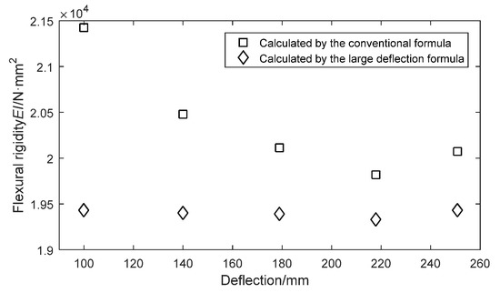
Figure 5.
Deflection vs. flexural rigidity.
By substituting the EI values into Equations (3) and (5), the deflection curves of stalk AO could be fitted, and the results are shown in the Figure 6. The deflection curves of 0.06 N were fitted as an example and compared to the measured curve. The results showed that the curve fitted by the large deflection formula in combination with Simpson’s formula was close to the actual one, with the free end error and the maximum error being only 1.83% and 8.95%, respectively, while the curve fitted by the conventional equation greatly deviated from the actual curve, with the free end error and the maximum error both being 37.15%. The experiment validated the availability of the large deflection calculation formula in combination with Simpson’s formula to compute the deformation curve of rice stalks. Using the accurate calculated curve, a proper cutting height of rice stalk could be determined to optimize power configuration of harvesters and satisfy the requirement of special crops.
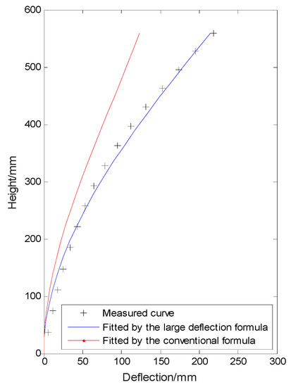
Figure 6.
The measured curve and the fitted curves.
4. Discussion
Though some studies have been conducted to obtain various mechanical properties of rice stalks, little work is available regarding the calculation of the deflection curves of rice stalks caused by reel operation because most of the parameters are acquired separately and the process of gaining the parameters is time-consuming and troublesome. The key point of the deflection calculation is to acquire accurate flexural rigidity (EI), and this paper introduced the large deflection calculation formula in combination with Simpson’s formula, which can obtain the EI directly without acquiring E and I separately, and could predict deflection curves conveniently with only deflection needing to be known.
The results obtained in this study and the calculation method can be applied in rice harvesting along with cutting energy data of rice plants at different cutting positions to lower cutting energy consumption and can also be used in other stalk crops like wheat, oilseed rape, sunflower, among others.
This study can be a basis for establishing a complete rice plant deformation model with the existence of the ear, leaves, and extra stalk above the acting point of the reel. This could be seen as a whole part forming the initial deflection of rice plant, which will be the next research direction of our team.
Author Contributions
Conceptualization, M.H. and A.C.; methodology, M.H.; software, M.H.; validation, A.C., Y.L. and L.X.; formal analysis, M.H.; investigation, M.H.; resources, M.H.; data curation, A.C.; writing—original draft preparation, M.H.; writing—review and editing, Y.L. and L.X.; visualization, Y.L.; supervision, Y.L.; project administration, Y.L.; funding acquisition, Y.L.
Funding
This research was funded by Chinese government, grant number 2016YFD0702004.
Acknowledgments
We kindly like to thank Lei X. for providing test materials to conduct the experiments at the Sanhu Farm, Jingzhou, Hunan province of China.
Conflicts of Interest
The authors declare no conflict of interest.
References
- Chen, J.; Yangyang, C.; Xuan, C.; Xuelei, W.; Shuqing, W. Design of Control System of Combine Harvester Louver Sieve Angle Based on Arm. In Proceedings of the International Conference on Electronics Information Engineering, Phuket, Thailand, 1 January 2017. [Google Scholar]
- Chen, J.; Wu, P.; Xu, K. Remote Fault Information Acquisition and Diagnosis System of the Combine Harvester Based on Labview. In Proceedings of the Applied Mechanics, Mechatronics Intellligent Systems International Conference AMMIS2015, Nanjing, China, 19–20 June 2015; pp. 285–292. [Google Scholar]
- Cho, W.; Kurita, H.; Iida, M.; Suguri, M.; Masuda, R. Autonomous Positioning of the Unloading Auger of a Combine Harvester by a Laser Sensor and Gnss. Eng. Agric. Environ. Food 2015, 8, 178–186. [Google Scholar] [CrossRef]
- Jin, X.; Chen, K.; Ji, J.T.; Zhao, K.X.; Du, X.W.; Ma, H. Intelligent Vibration Detection and Control System of Agricultural Machinery Engine. Measurement 2019, 503–510. [Google Scholar] [CrossRef]
- Liang, Z.W.; Li, Y.M.; Xu, L.Z.; Zhao, Z. Sensor for Monitoring Rice Grain Sieve Losses in Combine Harvesters. Biosyst. Eng. 2016, 147, 51–66. [Google Scholar] [CrossRef]
- Qin, X.; Zhang, H.; Zheng, H.G. Research on Intelligent Retrieval System for Agricultural Information Resources Based on Ontology. J. Phys. Conf. Ser. 2019, 2, 1168. [Google Scholar] [CrossRef]
- Bo, X.; Liu, P.; Sun, X.; Yang, P.; Lu, S.; Peng, Y.; Mo, Y. Study on the Elastic Modulus and the Tensile Breaking Point of Rice Internode. J. Anhui Agric. Sci. 2007, 35, 5388–5389. [Google Scholar]
- Oduori, M.F.; Mbuya, T.O.; Sakai, J.; Inoue, E. Kinematics of the Tined Combine Harvester Reel. Agric. Eng. Int. CIGR J. 2012, 14, 53–60. [Google Scholar]
- Oduori, M.F.; Mbuya, T.O.; Sakai, J.; Inoue, E. Modeling of Crop Stem Deflection in the Context of Combine Harvester Reel Design and Operation. Agric. Eng. Int. CIGR J. 2012, 14, 21–28. [Google Scholar]
- Hirai, Y.; Inoue, E.; Mori, K. Application of a Quasi-Static Stalk Bending Analysis to the Dynamic Response of Rice and Wheat Stalks Gathered by a Combine Harvester Reel. Biosyst. Eng. 2004, 88, 281–294. [Google Scholar] [CrossRef]
- Ren, S.; Wu, M.; Xie, F.; Guan, C. Elastic Modulus Measurement of the Rape Stem. Res. Explor. Lab. 2015, 34, 38–41. [Google Scholar]
- Ince, A.; Uğurluay, S.; Güzel, E.; Özcan, M.T. Bending and Shearing Characteristics of Sunflower Stalk Residue. Biosyst. Eng. 2005, 92, 175–181. [Google Scholar] [CrossRef]
- Esehaghbeygi, A.; Hoseinzadeh, B.; Khazaei, M.; Masoumi, A. Bending and Shearing Properties of Wheat Stem of Alvand Variety. World Appl. Sci. J. 2009, 6, 1028–1032. [Google Scholar]
- Chattopadhyay, P.S.; Pandey, K.P. Mechanical Properties of Sorghum Stalk in Relation to Quasi-Static Deformation. J. Agric. Eng. Res. 1999, 73, 199–206. [Google Scholar] [CrossRef]
- Yu, X.; Zhang, W.; Lu, B.; Ru, Z. Model Analysis for Wheat Stem Lodging Resistance. J. Henan Inst. Sci. Technol. Nat. Sci. Ed. 2013, 06, 33–36. [Google Scholar]
- Inoue, E.; Young-keun, K.; Koichi, H.; Takashi, O.; Jun, K. Mechanical Characteristics of Rice Stalk. J. Jpn. Soc. Agric. Mach. 1998, 60, 97–102. [Google Scholar]
- Jiang, W.; He, L.; Yaqing, X.; Mingfu, F. The Analyses and Solution for Cantalever Beam of Variational Cross Section in Large Deflection. J. Nanchang Univ. Eng. Technol. 1998, 03, 12–16. [Google Scholar]
- Chen, Y. Calculating of Heavy Camber Cantalever Beam. J. Yanshan Univ. 2003, 03, 227–229. [Google Scholar]
- Yang, Y.; Xian, W. Calculation on Large Deflection of Beam Bending Using Numerical Integral Method. J. Qinghai Univ. Nat. Sci. 1998, 06, 17–22. [Google Scholar]
- Hult, J. A Fourth-Order Runge–Kutta in the Interaction Picture Method for Simulating Supercontinuum Generation in Optical Fibers. J. Lightwave Technol. 2007, 25, 3770–3775. [Google Scholar] [CrossRef]
- Ohta, K.; Hatsuo, I. Comparison among Several Numerical Integration Methods for Kramers-Kronig Transformation. Appl. Spectrosc. 1988, 42, 952–957. [Google Scholar] [CrossRef]
© 2019 by the authors. Licensee MDPI, Basel, Switzerland. This article is an open access article distributed under the terms and conditions of the Creative Commons Attribution (CC BY) license (http://creativecommons.org/licenses/by/4.0/).