Article

Singular Value Decomposition Channel Estimation in STBC MIMO-OFDM System

School of Mechanical, Electrical and Information Engineering, Shandong University, Weihai 264209, China
*
Author to whom correspondence should be addressed.
Appl. Sci. 2019, 9(15), 3067; https://doi.org/10.3390/app9153067
Submission received: 26 June 2019 / Revised: 19 July 2019 / Accepted: 26 July 2019 / Published: 29 July 2019
(This article belongs to the Special Issue Underwater Acoustic Communications and Networks)

Abstract

:
The multiple-input multiple-output orthogonal frequency division multiplexing (MIMO-OFDM) technology is the combination of the OFDM and MIMO technologies, which could improve the system capacity and make efficient utilization of the frequency spectrum. This paper utilizes space-time block coding (STBC) to achieve diversity gains and combat the channel fading. However, channel estimation is an essential block for space-time block decoding (STBD). Many channel estimation methods are utilized for the single antenna OFDM system, but they cannot be directly applied to the multiple antennas system due to the interference from other antennas. In this paper, orthogonal pilot sequences are designed to suppress the interference of pilot symbols from other transmit antennas. This paper also derives a minimum mean square error (MMSE) channel estimation method in MIMO-OFDM systems. The MMSE method involves the inverse operation of the channel autocorrelation matrix, which has a large calculation complexity. To further reduce the complexity of the MMSE method, the singular value decomposition (SVD) is used to decompose the channel autocorrelation matrix, which avoids the inverse operation. Simulation results verify that the SVD channel estimation method with comb-type pilots and STBC can be effectively adapted to multipath propagation conditions.

Graphical Abstract

1. Introduction

Orthogonal frequency division multiplexing (OFDM) and multiple-input multiple-out (MIMO) technologies have been widely used in wireless communication systems [1,2]. The OFDM technology improves the spectrum utilization efficiency. Moreover, inter-symbol interference (ISI) can be avoided by adding the cyclic prefix (CP), which is inserted in the front of the OFDM symbol. The OFDM technology can flexibly select suitable subcarriers for transmission, so the spectrum resource allocation is more flexible. The MIMO technique with multiple antennas at both transmitter and receiver can increase system capacity and link reliability in the multipath propagation environment [3,4]. Hence, the combination of MIMO and OFDM technologies could improve the system performance.
By using specially designed channel codes at the transmitter and channel decoding at the receiver in MIMO-OFDM systems, space-time block coding (STBC) can provide diversity transmission gains and combat channel fading effectively. Hence, STBC is widely used in MIMO-OFDM systems [5]. Space-time block decoding (STBD) requires accurate channel state information (CSI). Due to the effect of additive white Gaussian noise (AWGN) and interference between antennas, CSI cannot be easily obtained in STBC MIMO-OFDM systems. Hence, channel estimation is a key technology to improve the STBC MIMO-OFDM system performance.
There have been many studies on channel estimation in single antenna OFDM systems. Pilot-based channel estimation methods are widely used in communication systems. Pilot-based channel estimation method estimates the channel by inserting the known pilot sequences into the transmitted OFDM symbols [6,7]. Pilot symbols are inserted in various patterns, such as block-type, comb-type, and scatter-type to adapt to different channel environments. The comb-type and scatter-type pilots are more adapt to the fast fading channel and block-type pilot is more adapt to the slow fading channel [8]. The least square (LS) channel estimation method is very simple and has low complexity [9]. However, the performance of the LS channel estimation method is poor because it is heavily affected by noise. The threshold channel estimation method filters out AWGN in channel coefficients by setting an appropriate threshold. However, the choice of the threshold has great impact on system performance. It is very difficult to select the appropriate threshold to filter out the noise as much as possible. A linear filtering LS (LFLS) channel estimation method was proposed in [10]. It can keep the energy of the main paths and remove the effect of AWGN. However, the disadvantage of the LFLS method is that the suppression factor of linear filter changes with the change of the channel environment. A novel channel estimation method based on the time-domain threshold was proposed in [11]. The threshold value was determined by obtaining a standard deviation of estimation noise through the wavelet decomposition of the frequency-domain estimated channel coefficients. This method obtained an appropriate threshold through the wavelet decomposition to filter out the AWGN. However, it cannot be directly applied to multiple antennas systems. An iterative scatter-based channel estimation method for the OFDM/offset quadrature amplitude modulation (OQAM), which reduces the real and imaginary interferences at the receiver to improve the channel estimation, was proposed in [12]. In OFDM/OQAM systems, the orthogonal condition of the subcarriers is guaranteed from the complex domain to the real domain. OFDM/OQAM also does not use any CP, which improves the spectral efficiency and accuracy of channel estimation.
Inserting pilot sequences into the transmitted data would reduce the spectral efficiency. To solve this problem, the blind channel estimation method is proposed for OFDM systems [13,14]. The blind channel estimation method does not require inserting pilots at the transmitter. The relevance of input data and output data can be used to estimate the channel. The blind channel estimation method can transmit more data symbols in a certain time interval. However, blind channel estimation is a very complex method. The semi-blind channel estimation method has a good tradeoff between bandwidth utilization and computational complexity [15,16]. The semi-blind channel estimation is the combination of pilot-based and blind channel estimation methods. Semi-blind schemes are computationally simpler than blind channel estimation methods, at the cost of only requiring a few pilot symbols.
Channel estimation in the MIMO-OFDM system is more complex than that in the OFDM system due to the interference between transmit and receive antennas. Many studies are also focused on channel estimation in MIMO-OFDM systems. A fast blind subspace channel estimation method for STBC-OFDM systems based on the circular property of the channel matrix was proposed in [17]. This method has fast convergence property than conventional blind subspace channel estimation methods. However, it cannot estimate the strong frequency-selectivity and fast fading channels. A sparse Bayesian learning (SBL)-based channel estimation scheme was proposed in an STBC MIMO-OFDM wireless system [18]. The pilot-based SBL technique obtains successive updates of the approximately sparse MIMO channel based on an expectation maximization formulation for estimation of the SBL channel hyper parameters. The data aided SBL scheme utilizes the maximum likelihood symbol detection to further improve the system performance. Although this method has better performance, the complexity is further improved.
An optimal pilot pattern selection using the cat swarm optimization algorithm is applied in [19]. It improves the accuracy of channel estimation. During channel estimation, the pilots are optimally selected using the cat swarm optimization algorithm with the fitness of delay and phase, which reduces the mutual coherence and communication complexity. Under the condition of 20 or 100 users, the proposed method has the best bit error rate (BER) performance in static Rayleigh channels. However, it has poor performance in the fast fading channel. A joint maximum likelihood and MMSE estimation based signal detection is proposed for the combination system of radio over fiber link and MIMO-OFDM wireless channel [20]. It can automatically determine which kind of estimation method can be used according to the channel signal-to-noise ratio (SNR) condition. The advantages of this method are that it has low system complexity and improves the nonlinear effect of radio over fiber link. A robust semi-blind receiver combined with the Tucker-2 model was proposed in [21]. The proposed receiver has high spectral efficiency and can be used in multi-user massive MIMO systems. The BER performance decreases dramatically with the increase of SNR. However, this method cannot adapt to the fast fading environment.
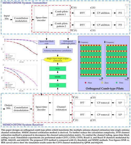
In this paper, an orthogonal pilot sequence is designed to suppress the interference of pilot symbols from other transmit antennas. The multiple antennas channel estimation problem can be transformed into the single antenna channel estimation problem, which reduces the complexity of the channel estimation. This paper also focuses on the analysis of the STBC and MMSE channel estimation method to improve the system performance. To further reduce the calculation complexity, the singular value decomposition (SVD) is used to decompose the channel autocorrelation matrix. This paper uses different constellation modulation modes such as quadrature phase shift keying (QPSK), 16-quadrature amplitude modulation (16QAM), and 64QAM. Different channel environments such as China DTV Test 1st (CDT1), CDT6, CDT8, Brazil A, and Brazil B are used to test the performance of the STBC MIMO-OFDM system. Simulation results verify that the SVD method combined with STBC has better BER performance than conventional LS and threshold channel estimation methods in the multipath channel environment.
The rest of this paper is organized as follows. Section 2 starts with an introduction of the system model, and then the STBC is described. Section 3 introduces two conventional channel estimation methods, which will be used for comparison analysis with the proposed channel estimation method. Section 4 illustrates the proposed SVD channel estimation method. Experimental results of the proposed method are presented in Section 5. Conclusions are given finally in Section 6.

2. System Model and STBC

2.1. STBC MIMO-OFDM System Model

This paper considers a system with two transmit and receive antennas, as shown in Figure 1.
For a system with N T > 2 transmit antennas and N R > 2 receive antennas, the new orthogonal pilot sequences need to be designed to suppress the interference from other transmit antennas. The space-time block code should be designed for N T > 2 transmit antennas. The system has N subcarriers in an OFDM block. At the transmitter side, the input bits are modulated in the constellation block. Then, the modulation symbols are sent to the space-time encoder. According to the principle of Alamouti criterion [22], the space-time coded signals are allocated to two antennas. The pilots are inserted into the OFDM symbols transmitted on two antennas, respectively. After the inverse fast Fourier transform (IFFT) operation, the data symbols X i α ( k ) are transformed into the time domain. The time-domain OFDM symbols x i α ( k ) can be shown as:
x i α ( k ) = 1 N n = 0 N 1 X i α e j 2 π k n / N , k = 0 , 1 , , N 1 ,
where α = 1 , 2 is the transmit antenna number and k represents the index of subcarriers. The comb-type pilots in two antennas are different and orthogonal. Then, the CP is inserted into the time-domain OFDM symbols in order to reduce the ISI. After the parallel to serial (P/S) block, the space-time block coded signals are transmitted from two antennas, respectively. In the process of channel propagation, the transmitted symbol will suffer from the multipath fading and AWGN. The channel environment will affect the correct receive of the receiver.
At the receiver, the received serial OFDM symbols are transformed into parallel in the serial to parallel (S/P) block. Then, the CP is removed from the parallel OFDM symbols. After removing the CP, the time-domain received OFDM symbols y i β ( k ) are transformed into frequency domain in the fast Fourier transform (FFT) block. β = 1 , 2 is the receive antenna number. The received symbols in the frequency domain can be written in vector form as:
Y i = H i X i + W i ,
where X i = [ X i 1 , X i 2 ] T are the transmitted OFDM symbols of the i -th signal frame on two transmit antennas. Y i = [ Y i 1 , Y i 2 ] T and W i = [ W i 1 , W i 2 ] T are the received OFDM symbols and AWGN on two receive antennas, respectively. H i denotes the 2 × 2 channel matrix. Then, the comb-type pilots are extracted to estimate the CSI. Using the estimated CSI, the frequency-domain symbols are decoded in the space-time decoder block. The signals at multiple receive antennas are decoded using CSI provided by the channel estimator. Therefore, channel estimation is a critical module for STBC MIMO-OFDM systems. Finally, OFDM symbols are demodulated into bits data in the constellation demodulation block.

2.2. STBC and STBD

Diversity technology is an important part of the multiple antennas technology. Diversity technology uses multiple antennas to receive or transmit signals carrying the same information, thereby improving the reliability of transmission. Diversity gains can be obtained by using the STBC technology at the transmitter. At the receiver, STBD only requires simple linear operation. In MIMO-OFDM systems, STBC is a key technology to improve the system performance. The Alamouti code is a complex orthogonal STBC specially designed for two transmit antennas [22]. According to the space-time coding scheme proposed by Alamouti, the symbols of the i frame and i + 1 frame on two transmit antennas are space-time coded in the frequency domain. Taking the first two frames of the OFDM symbols as an example, the model of the space-time encoder is shown in Figure 2.
As shown in Figure 2, the input bits are modulated by the constellation modulation. Then, the modulated symbols are encoded in the space-time encoder. The space-time coded signals are transmitted from two antennas. After the IFFT operation, the frequency-domain OFDM symbols X 1 and X 2 are transformed into time-domain OFDM symbols x 1 and x 2 . At a given symbol period, two signals are simultaneously transmitted from two antennas. The signals transmitted from the first antenna are denoted by x 1 and from the second antenna by x 2 . During the next symbol period, signal x 2 is transmitted from the first antenna, and signal x 1 is transmitted from the second antenna, where the superscript ( ) denotes the conjugate operation.
According to the Alamouti criterion [22], the OFDM symbols are sent out on the two transmit antennas, respectively. The Alamouti criterion between the i frame and i + 1 frame also can be shown as [22]:
X = [ X i ( k ) X i + 1 ( k ) X i + 1 ( k ) X i ( k ) ] ,
where X i ( k ) represents the frequency-domain data which transmits on the first antenna. It is located on the k -th subcarrier of the i -th OFDM symbol. X i + 1 ( k ) is the frequency-domain data which transmits on the second antenna. According to the estimated channel frequency response (CFR), the OFDM symbol after STBD in the receiver can be shown as:
[ X ^ ( i ) X ^ ( i + 1 ) ] = [ Y 1 ( i ) H ^ 1 , 1 * ( i ) + Y 1 * ( i + 1 ) H ^ 2 , 1 ( i ) + Y 2 ( i ) H ^ 1 , 1 * ( i ) + Y 2 * ( i + 1 ) H ^ 2 , 2 ( i ) Y 1 ( i ) H ^ 2 , 1 * ( i ) Y 1 * ( i + 1 ) H ^ 1 , 1 ( i ) + Y 2 ( i ) H ^ 2 , 2 * ( i ) Y 2 * ( i + 1 ) H ^ 1 , 2 ( i ) ] | H ^ 1 , 1 ( i ) | 2 + | H ^ 1 , 2 ( i ) | 2 + | H ^ 2 , 1 ( i ) | 2 + | H ^ 2 , 2 ( i ) | 2 ,
where X ^ ( i ) and X ^ ( i + 1 ) are the i -th and i + 1 -th STBD OFDM symbols, respectively. Y 1 ( i ) is the i -th received symbol from the first antenna. Y 2 ( i ) is the i -th received symbol from the second antenna. H ^ 1 , 1 ( i ) represents the estimated CFR between the first transmit antenna and the first receive antenna. H ^ 1 , 2 ( i ) represents the estimated CFR between the first transmit antenna and the second receive antenna. H ^ 2 , 1 ( i ) represents the estimated CFR between the second transmit antenna and the first receive antenna. H ^ 2 , 2 ( i ) represents the estimated CFR between the second transmit antenna and the second receive antenna.

3. Conventional Channel Estimation Methods

3.1. LS Channel Estimation

LS channel estimation is widely used in OFDM systems and has low calculation complexity [9]. This method requires pilots to obtain the channel coefficients. The CFR of the LS channel estimation in pilot positons H ^ LS ( k p ) which can be represented as:
H ^ LS ( k p ) = Y ( k p ) X ( k p ) ,
where X ( k p ) represents the transmitted pilot symbols on the k p -th subcarrier. Y ( k p ) represents the received pilot symbols on the k p -th subcarrier. The spline interpolation method utilized in the MIMO-OFDM system can improve the channel estimation accuracy significantly. Hence, this paper uses spline interpolation to obtain the channel coefficients of all data symbols in the frequency domain.

3.2. Threshold Channel Estimation

The LS channel estimation method is widely used in OFDM systems due to its simple implementation. However, the disadvantage of the LS method is that it ignores the effect of AWGN. However, when the signals transmit from the channel, it will be affected by the AWGN inevitably. The AWGN will affect the accuracy of the estimated channel impulse response (CIR). At the same time, the BER of the system will increase due to the AWGN in the estimated CIR. Hence, AWGN is a key factor and it is critical to reduce the AWGN in the estimated CIR. Many noise suppression channel estimation methods have been studied to reduce the noise and improve the accuracy of channel estimation [10]. The threshold channel estimation method can filter out the AWGN, which can be shown in Figure 3.
Residual AWGN existing at the estimated LS channel coefficients in the time domain could be reduced by reasonable selection of a threshold value. The threshold channel estimation results h ^ thre , i ( k ) after noise suppression are expressed as [23]:
h ^ thre , i ( k ) = { h ^ LS , i ( k ) , | h ^ LS , i ( k ) | λ 0 , | h ^ LS , i ( k ) | < λ   , 0 k < N ,
where λ is the threshold. Its value is relevant to the noise variance σ ^ n 2 . It will change with the change of the dynamic channel because the noise is difficult to separate from the channel. The CFR H ^ thre , i ( k ) can be obtained by the FFT operation of h ^ thre , i ( k ) .

4. The Proposed SVD Channel Estimation Method

LS and threshold methods presented in Section 3 can easily be implemented in OFDM systems. However, the OFDM symbols received by the receiver of the MIMO-OFDM system are the linear superposition of transmit symbols on each transmit antenna which can be presented as:
Y β = α = 1 N T H α , β X α , β ,
where the N × 1 vector Y β is the received OFDM symbol in the β -th receive antenna. N T is the number of the transmit antennas. The N × N diagonal matrix H α , β is the CFR between the α -th transmit antenna and the β -th receive antenna. The N × 1 vector X α , β is the transmitting symbol between the α -th transmit antenna and the β -th receive antenna. The pilot symbols can be orthogonal to eliminate the interference between the transmit antennas and receive antennas. Hence, this paper designs an orthogonal comb-type pilot pattern which is shown in Figure 4.
As shown in Figure 4, the green filling block represents transmitted data symbols. The yellow filling block represents zero, and the red filling block represents the transmitted pilot symbol. The pilot positions of the two antennas are orthogonal to each other, and the pilot symbols are orthogonal to each other. According to this pilot pattern, for a particular transmit antenna pair, the pilot symbols cannot be affected by other transmit antenna symbols. As a result, MIMO channel estimation can be converted into a number of independent single input and single output channel estimation problems. The estimated CFR H ^ LS α , β ( k p ) between the α -th transmit antenna and the β -th receive antenna according to the LS method which can be represented as:
H ^ LS α , β ( k p ) = Y α , β ( k p ) X α ( k p ) ,
where Y α , β ( k p ) is the received pilot symbol on the k p -th subcarrier between the α -th transmit antenna and the β -th receive antenna. X α ( k p ) is the transmitted pilot symbol on the k p -th subcarrier of the α -th transmit antenna. According to the spline interpolation, the CFR H ^ LS α , β in data positions can be obtained.
In the threshold channel estimation method, it is difficult to choose the appropriate threshold to suppress the noise in channel coefficients, which restrains the application in real scenario. The MMSE channel estimation method has better performance than the LS and threshold methods since it is optimum in minimizing the mean square error (MSE) of the channel estimates in the presence of AWGN. According to the pilot sequence designed in Figure 4, the MMSE channel estimation can be directly applied in STBC MIMO-OFDM systems without increasing the computational complexity. However, the MMSE channel estimation method requires the inverse operation of the channel correlation matrix, which has a large amount of computation. To further reduce the calculation complexity, the SVD method is used to decompose the channel autocorrelation matrix which avoids the matrix inversion operation. In Appendix A, the MMSE channel estimation method in STBC MIMO-OFDM systems can be represented as:
H ^ MMSE α , β = R HH ( R HH + σ ^ n 2 ( X p X p H ) 1 ) 1 H ^ LS α , β ,
where R HH = E ( H H H ) is the N × N channel autocorrelation matrix. X p is the transmitted pilot symbol. The N × 1 vector H ^ LS α , β is the CFR obtained by the LS method. The superscript ( ) H denotes the Hermitian transpose. σ n 2 is the variance of the AWGN in the channel. The complexity of the MMSE can be significantly reduced by averaging the transmitted pilot data. The term ( X p X p H ) 1 in Equation (9) can be replaced by its expected value of ( X p X p H ) 1 . The expected value of ( X p X p H ) 1 can be represented as:
E [ ( X p X p H ) ] 1 = E ( | 1 / x k | 2 ) I ,
where x k denotes the pilot symbols in matrix X p and I is the N × N identity matrix. Defining the SNR as E ( | x k | 2 ) / σ n 2 , the simplified MMSE channel estimator can be represented as [20]:
H ^ MMSE α , β = R HH ( R HH + φ SNR I ) 1 H ^ LS α , β ,
where φ = E ( | x k | 2 ) E ( | 1 / x k | 2 ) is a constant value depending on the signal constellation. For QPSK, its value is 1; for 16QAM, its value is 17/9; for 64QAM, φ is 13/5. To further reduce the complexity of the MMSE estimator, the SVD is used to decompose the channel autocorrelation matrix. The SVD of the channel autocorrelation matrix R HH is [24]:
R HH = U Λ V H ,
where U and V are N × N unitary matrices containing the singular vectors, and Λ is a N × N diagonal matrix containing the singular values λ 1 , λ 2 , , λ N on its diagonal in descending orders. The SVD method can be represented as [24]:
H ^ SVD α , β = U Δ V H H ^ LS α , β ,
where Δ is a N × N diagonal matrix and the elements on its diagonal are:
δ k = { λ k λ k + φ SNR , k = 1 , 2 , , l , 0 , k = l + 1 , l + 2 , , N ,
where l is the length of the CP.

5. Simulation Results

The BER performance of the proposed SVD channel estimation method is shown in this section. The simulation is performed in static multipath channel environments and adopts three constellation modulation modes of QPSK, 16QAM, and 64QAM, respectively. The Rayleigh fading multipath channel models are CDT1, CDT6, CDT8, Brazil A, and Brazil B channels [23,25]. These channels have six paths. Each channel has a different delay time and power. These channels have different frequency-selectivity.
The main simulation parameters based on the STBC MIMO-OFDM system are presented in Table 1. The profiles for the CDT1, CDT6, and CDT8 channel models are shown in Table 2. The profiles for the Brazil A and Brazil B channel models are shown in Table 3.
Four channel estimation methods, LS, threshold, MMSE, and SVD, are presented in the STBC MIMO-OFDM system. As can be seen from Table 1, in the STBC MIMO-OFDM system, different modulation modes, such as QPSK, 16QAM, and 64QAM, are applied to test the system performance. There are two transmit antennas and two receive antennas in the STBC MIMO-OFDM system. The pilot interval is one subcarrier. The total number of subcarriers is 2048. The CP occupies 256 subcarriers. One OFDM block consists of 10 OFDM symbols. The comb-type pilot pattern in Figure 4 is used to estimate the CSI.
Under the QPSK, 16QAM, and 64QAM modulation modes, the BER performance curves in the CDT1 channel are shown in Figure 5, Figure 6 and Figure 7, respectively.
As can be seen from Figure 5, the BER curves of four channel estimation methods show a downward trend. The LS method does not suppress the AWGN. Hence, its performance is the worst. Although the SVD method is a simplification of the MMSE method, its performance is very close to that of the MMSE method. Since the energy of the channel is mainly concentrated on the first l singular values of the channel autocorrelation matrix. The noise suppression performance of the proposed SVD channel estimation method is similar to that of the MMSE method. Hence, the performance of the proposed SVD method is very close to that of the MMSE method. At the BER of 10 2 , the SVD method outperforms the threshold and LS methods by about 2.7 dB and 6.3 dB SNR gains, respectively. At the BER of 10 3 , the SNR loss is about 1.3 dB between the threshold and SVD methods, and a 5.9 dB SNR loss between the LS and SVD methods. Hence, the SVD method increases the accuracy of channel estimation and can be used to estimate the slightly frequency-selectivity CDT1 channel.
As can be seen from Figure 6, as the SNR increases in the STBC MIMO-OFDM system, the simulation results of four channel estimation methods are decreased in terms of BER. Under the same conditions, the proposed SVD method has the lowest BER. Therefore, it provides the best BER performance especially under high SNR range. The LS method has the worst BER performance. At the BER of 10 2 , compared with the threshold channel estimation method, the SVD method has about 4.7 dB SNR gains. At the BER of 10 3 , the SVD method outperforms the threshold channel estimation method by about 2.9 dB SNR gains. Hence, under the 16QAM modulation mode, the SVD method can also be well applied to the STBC MIMO-OFDM system.
In the 64QAM modulation, one symbol carries six binary bits, thus increasing the transmission rate in the MIMO-OFDM system. Under the condition of two transmit and two receive antennas, the 64QAM modulation can provide various phases, it could significantly increase the transmission rate. As can be seen from Figure 7, under the 64QAM modulation mode, the proposed SVD method also has good performance. Hence, the proposed method can adapt to the 64QAM modulation mode.
Under the QPSK, 16QAM, and 64QAM modulation modes, the BER performance curves in the CDT6 channel are shown in Figure 8, Figure 9 and Figure 10, respectively.
Figure 8 and Figure 9 are simulated under the CDT6 channel environment. The BER of four channel estimation methods under the CDT6 channel is higher than in the CDT1 channel due to the stronger frequency-selectivity of the CDT6 channel. In Figure 8, at the BER of 10 2 , the SVD method outperforms the threshold and LS methods by about 1.8 dB and 6.4 dB SNR gains, respectively. At the BER of 10 3 , compared with the threshold method, the SVD method has about 0.35 dB SNR gains. In Figure 9, although the BER performance of the 16QAM modulation mode is worse than that of the QPSK modulation mode, the SVD method still has good performance. At the BER of 10 2 , the SVD method outperforms the threshold method by about 3.1 dB SNR gains. To clearly see the SNR gains between the SVD and MMSE methods, this paper amplifies the green box part in Figure 9. It can be seen from the amplified part, the SVD method outperforms the MMSE method by about 0.3 dB SNR gains at the BER of 2 × 10 1 . Hence, SVD channel estimation can be well used in the CDT6 channel to obtain the CFR. As can be seen from Figure 10, the proposed SVD method has good performance under the CDT6 channel with the 64QAM modulation mode due to fact that the proposed SVD method can suppress the noise effectively. The 64QAM modulation includes 64 constellation points and is more susceptible to AWGN. The LS and threshold methods cannot suppress the AWGN effectively. Hence, with the increase of SNR, the BER curves of the LS and threshold methods decrease slowly.
Under the QPSK and 16QAM modulation modes, the BER performance curves in the CDT8 channel are shown in Figure 11 and Figure 12, respectively.
As can be seen from Figure 11 and Figure 12, the BER curves of four channel estimation methods show a downward trend. The performance with the QPSK and 16QAM modulation modes is presented in the CDT8 channel. The CDT8 channel has stronger frequency-selectivity than the CDT6 channel. However, the proposed SVD method still shows the advantages of channel estimation in MIMO-OFDM systems. In Figure 11, at the BER of 5 × 10 2 , compared with the threshold and LS methods, the SVD method has about 3.3 dB and 6.9 dB SNR gains, respectively.
In Figure 12, at the BER of 10 1 , the SVD method outperforms the threshold and LS methods by about 7.1 dB and 12.7 dB SNR gains, respectively. The threshold channel estimation method does not perform well due to an inaccurate selection of the threshold. The SVD method can suppress the noise effectively and has better performance than threshold and LS channel estimation methods. Hence, the SVD channel estimation method can show obvious advantages in the CDT8 channel with a strong frequency-selectivity.
Under the 16QAM and 64QAM modulation modes, the BER performance curves in Brazil A channel are shown in Figure 13 and Figure 14, respectively.
As can be seen from Figure 13 and Figure 14, the proposed SVD channel estimation method can be well applied to the Brazil A channel. In Figure 13, at the BER of 10 2 , the SVD method outperforms the threshold method by about 4.9 dB SNR gains. At the BER of 10 3 , the SVD method outperforms the threshold method by about 3.1 dB SNR gains. In Figure 14, the SVD method has a good performance in the 64QAM modulation scheme. With the increase of SNR, the BER curves of the LS and threshold methods decrease slowly due to the influence of AWGN. At the BER of 6 × 10 2 , the proposed SVD method has about 0.27 dB SNR gains than the MMSE method. Although the performance of the SVD method is only slightly better than that of the MMSE method, the selected singular values can recover the information of CSI to a great extent and suppress the noise at the same time.
Under the 16QAM and 64QAM modulation modes, the BER performance curves in the Brazil B channel are shown in Figure 15 and Figure 16, respectively.
The strong frequency-selectivity of the Brazil B channel will reduce the BER performance of channel estimation methods. However, the SVD channel estimation method has a better performance than LS and threshold methods. In Figure 15, at the BER of 10 1 , the SVD method outperforms the threshold and LS methods by about 7.4 dB and 12.4 dB SNR gains, respectively. In Figure 16, the SVD method has a better performance than the threshold and LS methods under the Brazil B channel. The BER performance curves of the SVD channel estimation method decrease with the increase of SNR. At the BER of 2 × 10 1 , the proposed SVD method outperforms the MMSE method by about 0.3 dB SNR gains. Hence, the SVD channel estimation method can be used under the condition of the 64QAM modulation and strong frequency-selectivity Brazil B channel.
The computational complexity of four channel estimation methods is shown in Table 4. It can be seen that there is no multiplication in the LS and threshold methods. Both the LS and threshold methods only need the N points division. Hence, the LS and threshold channel estimation methods have a low complexity. However, these two methods could not provide a good BER performance in multipath channels. In the MMSE channel estimation method of Equation (11), R HH is a N × N channel autocorrelation matrix. The inverse of R HH is a N × N matrix. The inverse operation of R HH has a high calculation complexity. The CFR H ^ LS α , β obtained from the LS channel estimation method is a N × 1 vector. Hence, the MMSE channel estimation method needs the N 3 point multiplication and has the highest calculation complexity among these four channel estimation methods. In the SVD channel estimation method of Equation (13), after the SVD operation of the channel autocorrelation matrix R HH , U and V are N × N matrices. Δ is a N × N diagonal matrix. Since the number of significant taps is much lower than the number of subcarriers, there will be only a few significant singular values in Δ . Hence, the first l values in the diagonal of Δ are retained and other values are set to zero. l is the length of CP. The SVD method simplifies the channel estimation complexity and it only needs the l 3 point multiplication.
Although the SVD of the channel autocorrelation matrix reduces the number of multiplication for the channel estimation, obtaining the SVD of the autocorrelation matrix by itself is computationally complex like the inverse operation. The SVD operation of the channel autocorrelation matrix has a certain complexity, but it only decomposes the channel autocorrelation matrix once. With the increases of SNR, the SVD operation is not performed. However, the inverse operation of the channel autocorrelation matrix is required for every change of SNR. The inverse operation of the N × N channel autocorrelation matrix also has a high complexity when the number of subcarriers N is large. Hence, the proposed SVD method has a lower calculation complexity than the MMSE method.

6. Conclusions

To obtain diversity gains and combat multipath channel fading, STBC is analyzed and utilized in the STBC MIMO-OFDM system in this paper. To apply the channel estimation method in a single antenna system to multiple antennas system without increasing the computational complexity, an orthogonal pilot sequence is designed to avoid interference between antennas. This paper derives the MMSE channel estimation method. To further simplify the computational complexity of the MMSE method, SVD is applied to decompose the channel autocorrelation matrix, which avoids the matrix inversion operation. Simulation results have verified that the SVD channel estimation method with the comb-type pilots and STBC have good performance and can adapt to the strong frequency-selectivity multipath fading channel.
The proposed SVD method is also compared with the conventional LS and threshold channel estimation methods. The BER performance of the proposed SVD method is better than that of the two conventional methods in the QPSK, 16QAM, and 64QAM modulation modes. Although the SVD method simplifies the MMSE channel estimation method, the BER performance of the SVD method maintains comparable performance with the MMSE method.

Author Contributions

R.T. and X.Z. conceived the algorithm and designed the experiments; R.T. performed the experiments; X.Z. and C.W. analyzed the results; R.T. drafted the manuscript; R.T., X.Z., and C.W. revised the manuscript. X.Z. supervised the project. All authors read and approved the final manuscript.

Funding

This work was supported by the National Natural Science Foundation of China (No. 61702303) and the Natural Science Foundation of Shandong Province, China (No. ZR2017MF020).

Acknowledgments

The authors gratefully acknowledge the technical assistance of DL850E ScopeCorder administrated by Xiaoli Wang.

Conflicts of Interest

The authors declare no conflict of interest.

Appendix A

Defining H ^ LS = X 1 Y = H ˜ , we denote the MMSE channel estimation by:
H ^ MMSE = A H ˜ ,
where A is a weighting matrix. The MSE of MMSE channel estimation can be represented as:
E ( | e | 2 ) = E ( | H H ^ MMSE | 2 ) ,
where e is the estimated error between the true CFR and estimated CFR based on the MMSE method. The MMSE channel estimation method has better performance than the LS and threshold methods since it is optimum in minimizing the MSE of the channel estimates in the presence of AWGN. The estimated error e and H ˜ are orthogonal, which can be represented as:
E ( e H ˜ H ) = E [ ( H H ^ ) H ˜ H ] = E [ ( H A   H ˜ ) H ˜ H ] = E ( H H ˜ H ) A E ( H ˜ H ˜ H ) = R H H ˜ A R H ˜ H ˜ = 0
According to Equation (A3), the weighting matrix A can be represented as:
A = R H   H ˜ R H ˜ H ˜ 1 ,
where R H ˜ H ˜ 1 is the autocorrelation matrix of H ˜ , which can be represented as:
R H ˜ H ˜ = E ( H ˜ H ˜ H ) = E [ X 1 Y ( X 1 Y ) H ] = E [ ( H + X 1 Z ) ( H + X 1 Z ) H ] = E [ H H H + X 1 Z H H + H Z H ( X 1 ) H + X 1 Z Z H ( X 1 ) H ] = E [ H H H ] + E [ X 1 Z Z H ( X 1 ) H ] = E [ H H H ] + σ n 2 ( X X H ) 1 = R HH + σ n 2 ( X X H ) 1
where Z is AWGN. The MMSE channel estimation can be represented as:
H ^ MMSE = R H H ˜ ( R HH + σ n 2 ( X X H ) 1 ) 1 H ˜ .
In the case of all pilots, R H H ˜ = R HH . According to the designed orthogonal pilot pattern, for a particular transmit antenna pair, the channel coefficients of the pilot symbols can be represented as:
H ^ MMSE α , β = R HH ( R HH + σ ^ n 2 ( X p X p H ) 1 ) 1 H ^ LS α , β .

References

  1. Liu, Y.S.; Tan, Z.H.; Hu, H.J.; Cimini, L.J.; Li, G.Y. Channel estimation for OFDM. IEEE Commun. Surv. Tutor. 2014, 16, 1891–1908. [Google Scholar] [CrossRef]
  2. Jung, Y.A.; You, Y.H. Efficient joint estimation of carrier frequency and sampling frequency offsets for MIMO-OFDM ATSC systems. Symmetry 2018, 10, 554. [Google Scholar] [CrossRef]
  3. Bölcskei, H.; Gesbert, D.; Paulraj, A.J. On the capacity of OFDM-based spatial multiplexing systems. IEEE Trans. Commun. 2002, 50, 225–234. [Google Scholar] [CrossRef] [Green Version]
  4. Ro, J.H.; Kim, J.K.; You, Y.H.; Song, H.K. Linear approximation signal detection scheme in MIMO-OFDM systems. Appl. Sci. 2018, 8, 49. [Google Scholar]
  5. Kohli, A.K.; Garg, S. High-rate STBC communication system using imperfect CSI under time-selective flat-fading environment. Wireless Pers. Commun. 2018, 99, 1231–1245. [Google Scholar] [CrossRef]
  6. Li, G.M.; Liao, G.S. A pilot-pattern based algorithm for MIMO-OFDM channel estimation. Algorithms 2017, 10, 3. [Google Scholar] [CrossRef]
  7. Pejoski, S.; Kafedziski, V. Estimation of sparse time dispersive channels in pilot aided OFDM using atomic norm. IEEE Wirel. Commun. Lett. 2015, 4, 397–400. [Google Scholar] [CrossRef]
  8. Adakane, D.V.; Vasudevan, K. An efficient pilot pattern design for channel estimation in OFDM systems. In Proceedings of the International Conference on Signal Processing, Computing and Control, Shimla, India, 26–28 September 2013; pp. 1–5. [Google Scholar]
  9. Lin, J.C. LS channel estimation for mobile OFDM communications on time-varying frequency-selective fading channel. In Proceedings of the International Conference on Communications, Scotland, UK, 24–28 June 2007; pp. 3016–3023. [Google Scholar]
  10. Zhou, X.; Ye, Z.; Liu, X.X.; Wang, C.Y. Channel estimation based on linear filtering least square in OFDM systems. J. Commun. 2016, 11, 1005–1011. [Google Scholar] [CrossRef]
  11. Lee, Y.S.; Shin, H.C.; Kim, H.N. Channel estimation based on a time-domain threshold for OFDM systems. IEEE Trans. Broadcast. 2009, 55, 656–662. [Google Scholar]
  12. Lélé, C. Iterative scattered-based channel estimation method for OFDM/OQAM. EURASIP J. Adv. Sign. Process. 2012, 1, 42. [Google Scholar] [CrossRef]
  13. Tseng, C.H.; Cheng, Y.C.; Chung, C.D. Subspace-based blind channel estimation for OFDM by exploiting cyclic prefix. IEEE Wirel. Commun. Lett. 2013, 2, 691–694. [Google Scholar] [CrossRef]
  14. Ghadrdan, S.; Ahmadian, M.; Salari, S.; Heydarzadeh, M. An improved blind channel estimation algorithm for OFDM systems. In Proceedings of the 5th International Symposium on Telecommunications, Tehran, Iran, 4–6 December 2010; pp. 421–425. [Google Scholar]
  15. Gulomjon, S.; Fu, Y.Q.; Sangirov, J.; Ye, F.; Olmasov, A. A performance analysis of optimized semi-blind channel estimation method in OFDM systems. In Proceedings of the 19th International Conference on Advanced Communications Technology, Pyeongchang, Korea, 19–22 February 2017; pp. 907–912. [Google Scholar]
  16. Nayebi, E.; Rao, B.D. Semi-blind channel estimation for multiuser massive MIMO systems. IEEE Trans. Signal Process. 2018, 66, 540–553. [Google Scholar] [CrossRef]
  17. Zhang, B.L.; Yu, J.L.; Yuan, Y.P.; Lai, J.W. Fast blind channel estimation for space-time block coded MIMO-OFDM systems. Telecommun. Syst. 2017, 65, 443–457. [Google Scholar] [CrossRef]
  18. Mishra, A.; Yashaswini, N.S.; Jagannatham, A.K. SBL-based joint sparse channel estimation and maximum likelihood symbol detection in OSTBC MIMO-OFDM systems. IEEE Trans. Veh. Technol. 2018, 67, 4220–4232. [Google Scholar] [CrossRef]
  19. Motade, S.N.; Kulkarni, A.V. Channel estimation and data detection using machine learning for MIMO 5G communication systems in fading channel. Technologies 2018, 6, 72. [Google Scholar] [CrossRef]
  20. Sun, X.K.; Qiao, R. Joint ML and MMSE estimation based signal detection for MIMO-OFDM radio over fiber system. In Proceedings of the 14th IEEE International Conference on High Performance Computing and Communications, Liverpool, UK, 25–27 June 2012; pp. 187–192. [Google Scholar]
  21. Du, J.H.; Han, M.; Hua, Y.; Chen, Y.Z.; Lin, H.Y. A robust semi-blind receiver for joint symbol and channel parameter estimation in multiple-antenna systems. Electronics 2019, 8, 550. [Google Scholar] [CrossRef]
  22. Alamouti, S.M. A simple transmit diversity technique for wireless communications. IEEE J. Sel. Areas Commun. 1998, 16, 1451–1458. [Google Scholar] [CrossRef]
  23. Zhou, X.; Wang, C.Y.; Tang, R.G.; Zhang, M.T. Channel estimation based on statistical frames and confidence level in OFDM systems. Appl. Sci. 2018, 8, 1607. [Google Scholar] [CrossRef]
  24. Desai, M.V.; Gupta, S.; Dalal, U.D. DCT-SVD based channel estimation technique in IEEE 802.16e DL-PUSC system. In Proceedings of the 2nd International Conference on Emerging Technology Trends in Electronics, Communication and Networking, Surat, India, 26–27 December 2014; pp. 1–6. [Google Scholar]
  25. Zhou, X.; Yang, F.; Song, J. Novel transmit diversity scheme for TDS-OFDM system with frequency-shift m-sequence padding. IEEE Trans. Broadcast. 2012, 58, 317–324. [Google Scholar] [CrossRef]
Figure 1. System model of the space-time block coding multiple-input multiple-output orthogonal frequency division multiplexing (STBC MIMO-OFDM) system.
Applsci 09 03067 g001
Figure 2. The STBC model of the MIMO-OFDM system.
Applsci 09 03067 g002
Figure 3. Threshold channel estimation method.
Applsci 09 03067 g003
Figure 4. Comb-type pilot pattern in two antennas: (a) antenna one; (b) antenna two.
Applsci 09 03067 g004
Figure 5. Comparisons of bit error rate (BER) performance in the case of quadrature phase shift keying (QPSK) modulation at the static China DTV Test 1st (CDT1) channel.
Applsci 09 03067 g005
Figure 6. Comparisons of BER performance in the case of 16-quadrature amplitude modulation (16QAM) modulation at the static CDT1 channel.
Applsci 09 03067 g006
Figure 7. Comparisons of BER performance in the case of 64QAM modulation at the static CDT1 channel.
Applsci 09 03067 g007
Figure 8. Comparisons of BER performance in the case of QPSK modulation at the static CDT6 channel.
Applsci 09 03067 g008
Figure 9. Comparisons of BER performance in the case of 16QAM modulation at the static CDT6 channel.
Applsci 09 03067 g009
Figure 10. Comparisons of BER performance in the case of 64QAM modulation at the static CDT6 channel.
Applsci 09 03067 g010
Figure 11. Comparisons of BER performance in the case of QPSK modulation at the static CDT8 channel.
Applsci 09 03067 g011
Figure 12. Comparisons of BER performance in the case of 16QAM modulation at the static CDT8 channel.
Applsci 09 03067 g012
Figure 13. Comparisons of BER performance in the case of 16QAM modulation at the static Brazil A channel.
Applsci 09 03067 g013
Figure 14. Comparisons of BER performance in the case of 64QAM modulation at the static Brazil A channel.
Applsci 09 03067 g014
Figure 15. Comparisons of BER performance in the case of 16QAM modulation at the static Brazil B channel.
Applsci 09 03067 g015
Figure 16. Comparisons of BER performance in the case of 64QAM modulation at the static Brazil B channel.
Applsci 09 03067 g016
Table 1. Parameters for STBC-OFDM systems.
ParametersSpecifications
System modelSTBC MIMO-OFDM
Modulation modeQPSK, 16QAM, 64QAM
Number of transmit antenna2
Number of receive antenna2
Pilot interval (subcarrier)1
CP length (subcarriers)256
Subcarrier number2048
OFDM block length10
Pilot typeComb-type
φ 1, 17/9, 13/5
Table 2. Profiles for China DTV Test 1st (CDT1), CDT6, and CDT8 multipath fading channels.
TapCDT1CDT6CDT8
Delay (μs)Power (dB)Delay (μs)Power (dB)Delay (μs)Power (dB)
1000000
2−1.8−20−18−10−18−1.8
30.15−20−1.8−20−200.15
41.8−100.15−20−201.8
55.7−141.8−10−105.7
618−185.7−14030
Table 3. Profiles for Brazil A and Brazil B multipath fading channels.
TapBrazil ABrazil B
Delay (μs)Power (dB)Delay (μs)Power (dB)
10000
20.15−20−18−10
32.22−20−1.8−20
43.05−100.15−20
55.86−141.8−10
65.93−185.7−14
Table 4. Comparison of complexity analysis.
Operation ModeLSThresholdMMSEProposed SVD
IFFT/FFT ( N points)1111
Addition/Subtraction0 N N 0
Multiplication00 N 3 l 3
Division N N N l

