Article

Quantitative Analysis of Soil Displacement Induced by Ground Loss and Shield Machine Mechanical Effect in Metro Tunnel Construction

1
Key Laboratory of Transportation Tunnel Engineering, Ministry of Education, Southwest Jiaotong University, Chengdu 610031, China
2
School of Civil Engineering, Changsha University of Science and Technology, Changsha 410076, China
3
Sichuan Vocational and Technical College of Communications, Chengdu 611130, China
*
Authors to whom correspondence should be addressed.
Appl. Sci. 2019, 9(15), 3028; https://doi.org/10.3390/app9153028
Submission received: 26 June 2019 / Revised: 22 July 2019 / Accepted: 24 July 2019 / Published: 26 July 2019

Abstract

:
In order to relieve the increasing ground traffic pressure in the process of urbanization in China, it is inevitable to build more metro lines. However, the stratum movement caused by tunneling affects the safety of adjacent underground structures and aboveground buildings. Therefore, how to evaluate and control the stratum movement is a prominent problem. In this paper, based on the engineering project of an interval tunnel between Shizishan Station and Chuanshi Station in Chengdu Metro Line 7, China, the action mechanism of stratum movement induced by shield tunneling is analyzed, and the effect factors are divided into two categories: ground loss factors and mechanical factors. Combining the advantages of Loganathan method and mirror source-sink method, a new solution of three-dimensional displacement induced by ground loss is proposed. Based on the elastic half-space Mindlin model, the displacement at any point induced by four mechanical effect factors is deduced. Finally, the total displacement is verified by field monitoring data and quantitative analyzed in various parts.

1. Introduction

With the acceleration of urbanization in China, the growth rate of urban land use is much lower than the urban population growth rate. The limited number of urban surface land resources can no longer meet people’s needs for living space. The development direction of urban space is gradually changing from the horizontal direction of extension to the vertical direction of intension, which has resulted in many underground structures [1,2,3,4]. Although the development of urban underground space has detailed plans and arrangements before construction, it still has some unpredictability in the long term. Therefore, the negative conditions that new underground structures create near the existing ones happen from time to time. As the main artery of underground traffic in modern cities, this phenomenon of metro tunnels is particularly prominent. Among many construction methods of metro tunnel, shield tunneling is becoming the preferred construction scheme because of its advantages of fast construction and small disturbance to stratum [5,6,7,8,9]. Although shield tunneling has many advantages as mentioned above, and the construction technology has made great progress in many years, due to the defects of geological conditions and construction technology, the advance of shield tunneling will inevitably create a disturbance, change the stress state of soil and cause stratum displacement. Therefore, how to evaluate and control the stratum displacement has always been a concern for engineers [10,11,12].
The important of this problem has prompted researchers to study many methods for predicting stratum displacement induced by shield tunneling. Based on the factors affecting stratum displacement, the methods can be divided into two categories. The first category concerns the ground loss factors during shield excavation, and the second addresses the mechanical effect factors. In terms of ground loss factors, empirical solution is one of the most commonly used methods. Peck assumed that the curve of land settlement trough satisfies the conditions of Gauss distribution and invariant stratum volume, as was deduced Peck’s empirical formula based on field monitoring data [13]. Celestino et al. [14] and many other researchers [15,16,17,18,19] noted that Peck’s empirical formula cannot accurately describe soil settlement trough in many cases and proposed improved empirical formulas under different geologic conditions. Besides empirical solution, there are also many researchers who contribute significantly through analytical solution [20,21,22,23], numerical simulation [24,25,26] and model testing [27,28]. In terms of mechanical effect factors, Mindlin’s solution is one of the well-known solutions to calculate the stress and displacement caused by a point load at an embedment depth in an elastic half-space [29]. Based on Mindlin’s solution, many modified analytical solutions are proposed [30,31,32,33]. For instance, Verruijt et al. derived a theoretical solution for the deformations of an elastic half-plane with a circular cavity, which is often used in tunnel excavation. [34,35].
However, most previous studies only consider the stratum displacement caused by ground loss factors, ignoring the influence of mechanical factors without clear theoretical basis [7,8,17,21]. A few studies containing mechanical factors are not thorough enough, and they are usually shown in the form of total displacement without the quantitative analysis of the proportion of stratum displacement caused by each factor [6,9,10]. In this paper, based on the engineering project of an interval tunnel between Shizishan Station and Chuanshi Station in Chengdu Metro Line 7, China, combining Loganathan empirical formula and mirror source-sink method, the stratum displacement caused by ground loss factors is calculated. The mechanical effect factors are divided into four parts and calculated based on the Mindlin solution. The proportion of stratum displacement caused by each factor is quantitatively analyzed, which can provide guidance for the stratum displacement calculation of shield tunneling in the future.

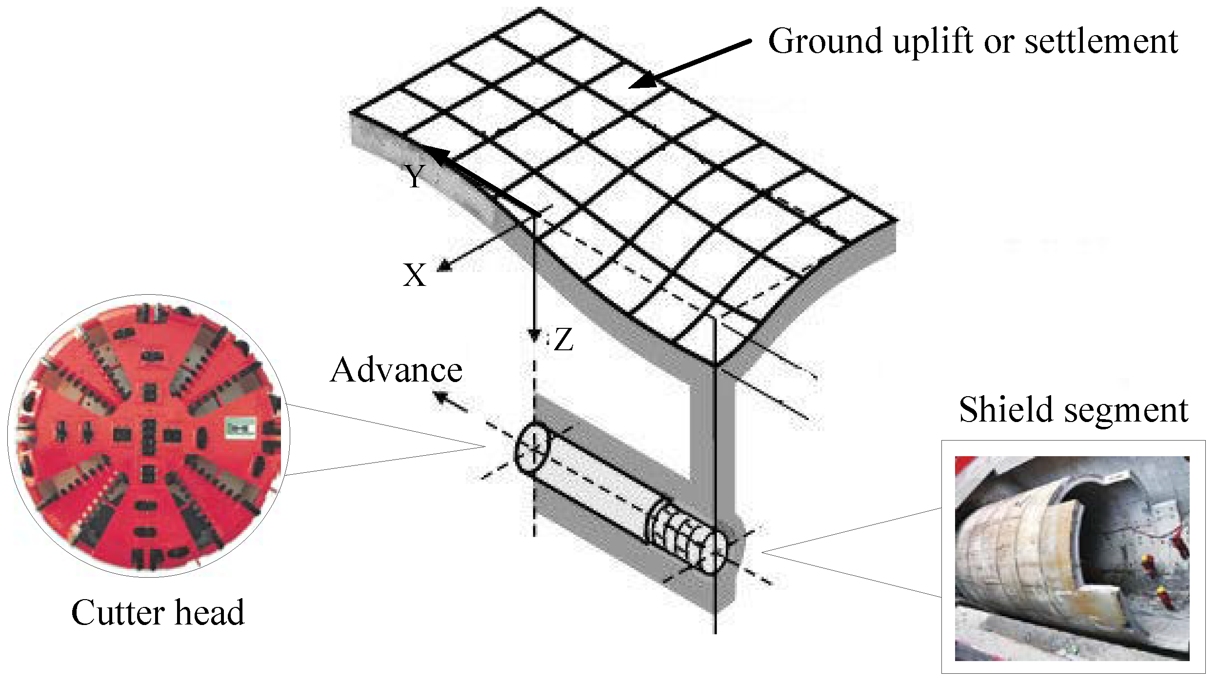
2. Engineering Background

The engineering project in this paper is an interval tunnel between Shizishan Station and Chuanshi Station in Chengdu Metro Line 7, China. The tunnel consists of two single-track tunnels with a total length of 970.4 m and a burial depth of 15 m, which is mainly located in weathered mudstone stratum and excavated by EPB (Earth Pressure Balanced) shield. The external diameter of shield and fabricated precast segment are 6 m and 6.28 m, respectively. The diagram of shield tunneling in diagram is shown in Figure 1.
In order to carry out the calculations, the parameters that need to be determined can be divided into two categories. The first category concerns the physical parameters of soil, such as elastic modules, Poisson’s ratio, etc. They are obtained from engineering geological reports and field experiments, as shown in Table 1. The second is the construction parameters of the shield machine, such as shield tunneling speed, strain rate of grouting layer, etc. The equipment used in this project is CREC153 EPB shield machine produced by China Railway Engineering Equipment Group, its parameters are shown in Table 2.

3. Ground Loss Effect Factors

Ground loss g is the primary cause of stratum settlement and deformation. During shield tunnel construction, the causes of ground loss include curved propulsion, shield steering adjustment, soil thrusting into the shield tail gap, head-down propulsion, head-up propulsion, and tunnel lining deformation. The ground loss can be calculated by using the Lee’s equation [36].
g = G P + U p + ω
where Gp is physical gap, it is the gap between the outer wall of the shield shell and the outer wall of the segment. In the field, synchronous grouting is used to decrease the physical gap, but due to the hydration reaction characteristics and the water permeation loss of cement slurry, there is still a residual gap Gp when the physical gap Gp is fully filled by grouting. Usually, Gp’ = Gp × βl, βl is slurry strain rate; Up is the plastic deformation of shield working face during tunnel excavation. Generally, Up = 0 when the EPB shield is used; ω is the additional ground loss induced by shield rectification, head-up propulsion, head-down propulsion and the soil consolidation in the tunneling disturbance zone. ω can be assumed to be 0 because the working face thrust of shield is equal to the soil pressure during most of the time.

3.1. Displacement Solution

Based on the Verruijt analytical formula [34,35], considering quantify ground loss with non-equivalent radial displacement, Loganathan [21] put forward a method for estimating stratum displacement caused by ground loss in undrained clays; the formula is as shown in Equation (2).
{ S z = R 2 { z H x 2 + ( z H ) 2 + ( 3 4 μ ) z + H x 2 + ( z + H ) 2 2 z [ x 2 ( z + H ) 2 ] [ x 2 + ( z + H ) 2 ] 2 } × ε x , z S x = R 2 x { 1 x 2 + ( z H ) 2 + ( 3 4 μ u ) x 2 + ( z + H ) 2 4 z ( z + H ) [ x 2 + ( z + H ) 2 ] 2 } × ε x , z
where R is tunnel external radius; H is burial depth of tunnel center; μ is Poisson’s ratio of soil; εx,z is the parameter of non-equivalent radial displacement, fitting by exponential function based on measured data, which can be expressed as Equation (3).
ε x , z = 4 g R + g 2 4 R 2 exp { | 1.38 x 2 ( H + R ) 2 + 0.69 z 2 H 2 | }
Considering that the displacement solution caused by ground loss derived by Loganathan is a two-dimensional solution, which is often a three-dimensional problem in actual engineering, it is necessary to extend the two-dimensional displacement solution to three-dimensional. The three-dimensional ground loss parameter εx,z,y can be extracted from the Sagaseta’ solution [20].
Sagaseta deduced the expression of ground displacement caused by tunnel construction by using the mirror source-sink method.
{ S x 0 = v l o s s 2 π x x 2 + H 2 [ 1 + y ( x 2 + y 2 + H 2 ) 1 2 ] S y 0 = v l o s s 2 π 1 ( x 2 + y 2 + H 2 ) 1 2 S z 0 = v l o s s 2 π H x 2 + H 2 [ 1 + y ( x 2 + y 2 + H 2 ) 1 2 ] S x 0 ( y ) = v l o s s π x x 2 + H 2 S z 0 ( y ) = v l o s s π H x 2 + H 2
where Vloss is ground loss. From Equation (4) it can be found:
{ S x 0 ( y ) = S x 0 ( y ) × 1 2 × [ 1 + y ( x 2 + y 2 + H 2 ) 1 2 ] S z 0 ( y ) = S z 0 ( y ) × 1 2 × [ 1 + y ( x 2 + y 2 + H 2 ) 1 2 ]
Equation (5) shows that the distribution of stratum displacement caused by shield construction (ground loss) along the Y axis satisfies the law of ½ × [1 + y/(x2 + y2 + z2)½]. Therefore, based on this law, the Loganathan’s solution is extended to the three-dimensional. It is noted that the coordinate system adopted in this paper is different from that used in the Sagaseta’s solution, so the distribution law should be revised, and its expression is as Equation (6):
ε y = 1 2 × [ 1 y ( x 2 + y 2 + H 2 ) 1 2 ]
The plane ground loss parameter εx,z is extended to three-dimensional parameter εx,z,y which can be seen as Equation (7). Then, three-dimensional stratum displacement solution, Equation (8) can be obtained by replacing εx,z in Equation (2).
ε x , y , x = ε y × ε x , z = [ 1 y ( x 2 + y 2 + H 2 ) 1 2 ] × 4 g R + g 2 8 R 2 exp { | 1.38 x 2 ( H + R ) 2 + 0.69 z 2 H 2 | }
{ S z = R 2 { z H x 2 + ( z H ) 2 + ( 3 4 μ ) z + H x 2 + ( z + H ) 2 2 z [ x 2 ( z + H ) 2 ] [ x 2 + ( z + H ) 2 ] 2 } × ε x , y , z S x = R 2 x { 1 x 2 + ( z H ) 2 + ( 3 4 μ ) x 2 + ( z + H ) 2 4 z ( z + H ) [ x 2 + ( z + H ) 2 ] 2 } × ε x , y , z

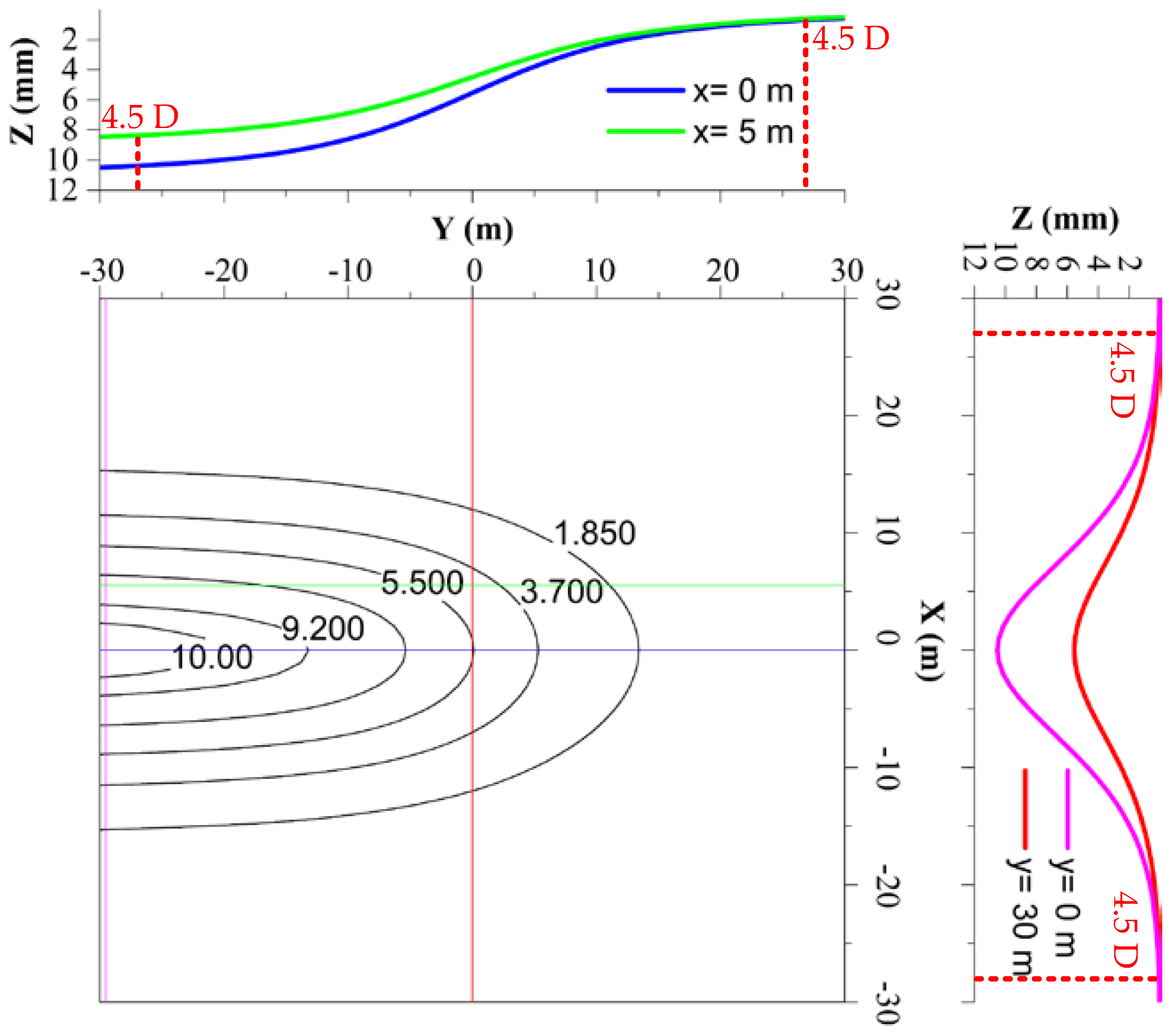
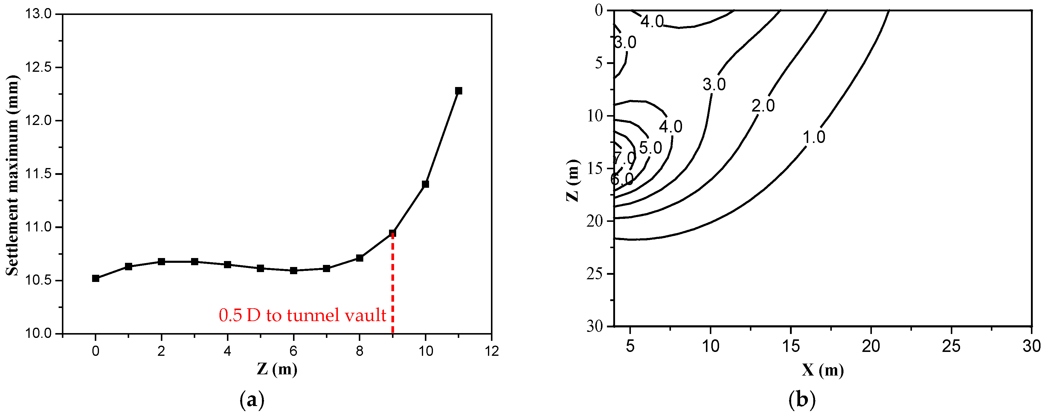
3.2. Quantitative Analysis

Ground loss g and several parameters of Table 1 can be brought into Equation (8) to calculate ground loss displacement, and the counter map of ground settlement are shown in Figure 2. As we can see it, ground settlement at 4.5 D (D for diameter of tunnel) behind shield tail is stable to maximum 10.51 mm, and its value at 4.5 D in front of shield tail is only 10% of maximum. Therefore, it can be considered that the influence range of ground loss is within 4.5 D behind and in front of shield tail. As for deep soil layer, when the vertical distance from tunnel vault is greater than 0.5 D, the settlement has little changes. However, while it is less than 0.5 D, the settlement increases rapidly, as shown in Figure 3a. This is because that with the redistribution of stress, a pressure arch will be formed around the tunnel. The soil in the arch is a loosening zone, which has a greater displacement, and the soil out of the arch tends to be stable. As we can see from Figure 3b, horizontal displacement of deep soil is mainly distributed in 1 D from the bottom of the tunnel.

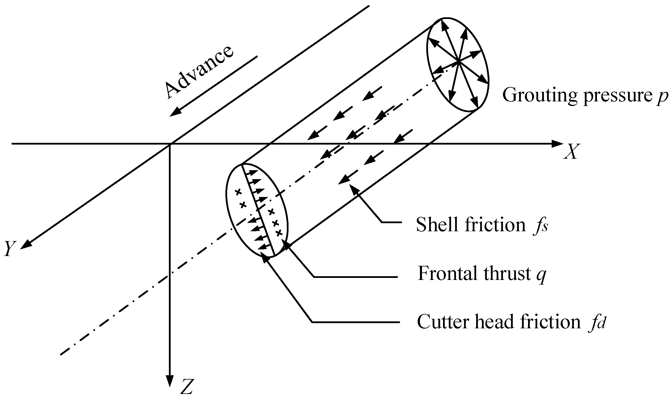
4. Mechanical Effect Factors

The shield machine has a complex mechanical interaction with the surrounding stratum when shield tunnel constructs. Based on the difference of sources and action modes, these mechanical effect factors can be divided into following categories, as Figure 4: Friction fd between the shield working face and the soil; Additional frontal thrust q on the shield working face; Shell Friction fs between the shield and the soil; Radial pressure p generated by synchronous grouting in shield tail gap.

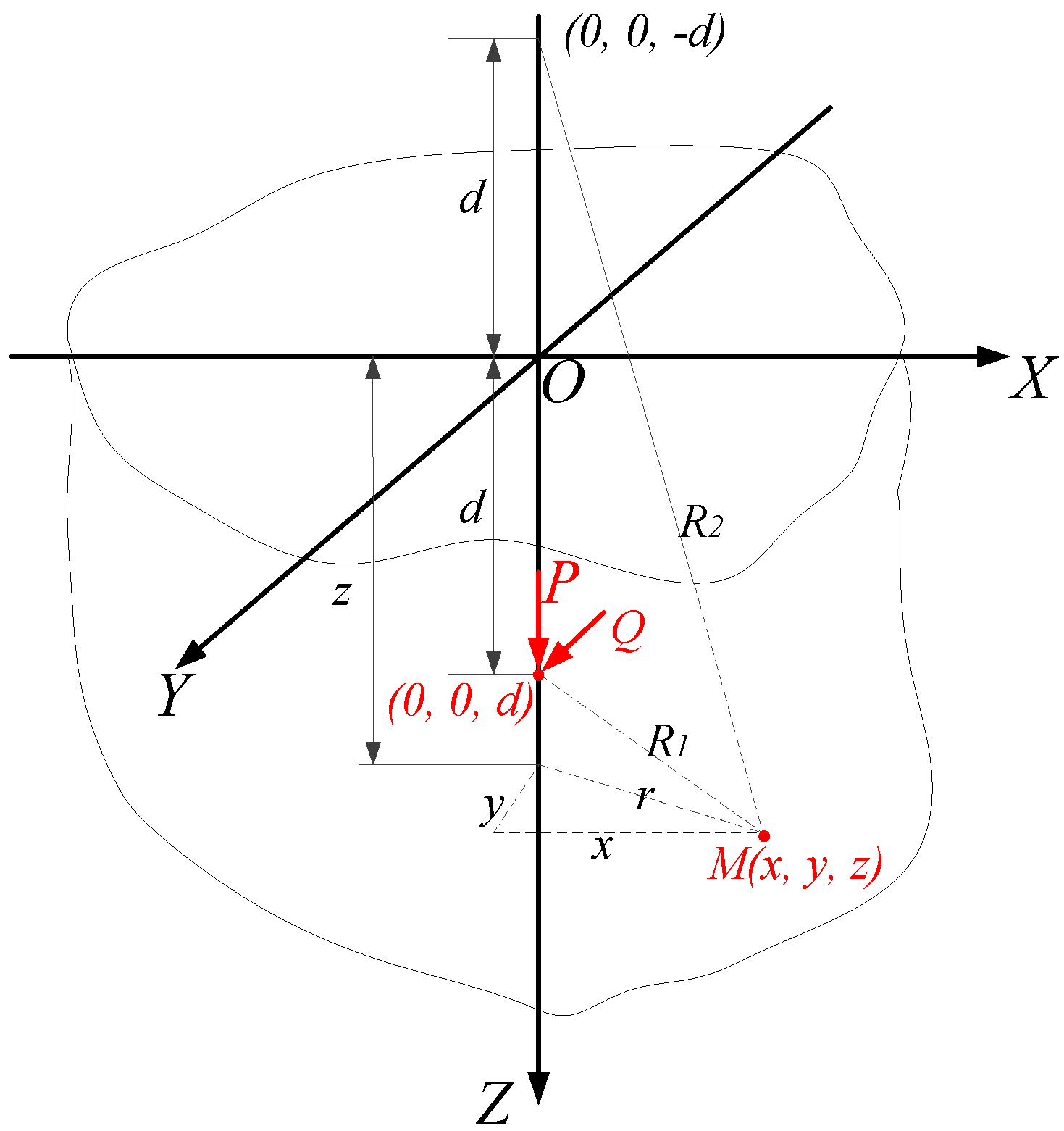
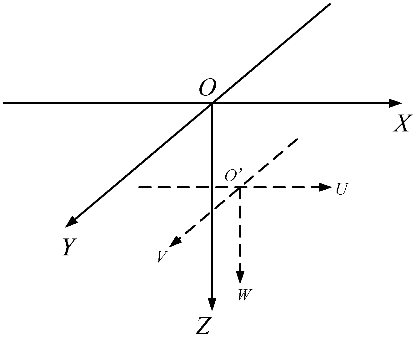
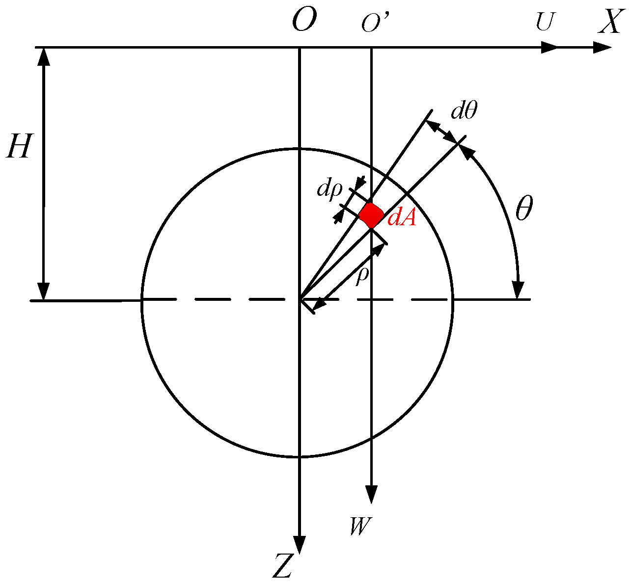
4.1. Mindlin’s Solutions

The displacement caused by point load at any point can be solved by using Mindlin theoretical solution in the elastic half-space shown in Figure 5 [25]. The above four categories of force can be decomposed into vertical and horizontal forces, then brought into Mindlin solution to calculate.
When there is a vertical concentrated load P at burial depth d, then the displacement Sx(y),V of x(y) direction and the displacement Sz,V of z direction at any point M (x, y, z) in space induced by the load P can be expressed as Equation (9):
{ S x ( y ) , V = P x ( y ) 16 π G ( 1 μ ) [ z d R 1 3 + ( 3 4 μ ) ( z d ) R 2 3 4 ( 1 μ ) ( 1 2 μ ) R 2 ( R 2 + z + d ) + 6 d z ( z + d ) R 2 5 ] S z , V = P 16 π G ( 1 μ )   [ 3 4 μ R 1 + 8 ( 1 μ ) 2 ( 3 4 μ ) R 2 + ( z d ) 2 R 1 3 + ( 3 4 μ ) ( z + d ) 2 2 d z R 2 3 + 6 d z ( z + d ) 2 R 2 5 ]
where μ is Poisson’s ratio; G is soil shear modulus.
When there is a horizontal concentrated load Q parallel to Y axis, pointing in the positive direction of the Y axis, then the displacement Sx,H of x direction, Sy,H of y, Sz,H of z at any point M (x, y, z) in space induced by the load Q can be expressed as Equation (10). While the horizontal concentrated load Q parallel to X axis, due to the symmetry of x and y, it only needs to exchange x and y in Equation (10).
{ S x , H = P x y 16 π G ( 1 μ ) [ 1 R 1 3 + 3 4 μ R 2 3 6 d z R 2 5 4 ( 1 μ ) ( 1 2 μ ) R 2 ( R 2 + z + d ) 2 S y , H = P 16 π G ( 1 μ ) [ 3 4 μ R 1 + 1 R 2 + y 2 R 1 3 + ( 3 4 μ ) y 2 R 2 3 + 2 d z R 2 3 ( 1 3 y 2 R 2 3 ) + 4 ( 1 μ ) ( 1 2 μ ) R 2 + z + d ( 1 y 2 R 2 ( R 2 + z + d ) ) ] S z , H = P y 16 π G ( 1 μ ) [ z d R 1 3 + ( 3 4 μ ) ( z d ) R 2 3 + 4 ( 1 μ ) ( 1 2 μ ) R 2 ( R 2 + z + d ) 6 d z ( z + d ) R 2 5 ]
Due to the location of load in Mindlin solution is at z axis, the coordinate of the formula above should be transformed to use when the location of load is at any point. The global coordinate system is xyz, let the local coordinate system be uvw and coordinate origin be O’ (m, n, k), shown in Figure 6. When coordinate is transformed, xyz are replaced by uvw, then let u = xm, v = yn, w = zk.

4.2. Quantitative Analysis of Additional Thrust q

When the shield machine advances, the whole machine is close to equilibrium state. However, large additional stresses still occur in the front of the cutter head, especially while plate-type panel cutter head with a small opening ratio is adopted. Wang built an extrusion model of cutter head and deduced the expression of additional thrust q based on the field monitoring data, as shown in Equation (11) [37].
q = 10.13 ( 1 μ ) E u π v ( 1 ξ ) 2 ( 1 + μ ) ( 3 4 μ ) D k ω + Δ p
where Eu is undrained elastic modulus; v is shield tunneling speed; ξ is cutter opening ratio; D is diameter of shield; k is closure number of cutters; ω is angular velocity of cutter head; Δp’ is extrusion pressure of cutters, generally takes 10–25 kPa.
Based on Equation (11) and parameters of Table 2, the additional thrust q is 280 kPa. This is similar to the measured value in previous studies, which is much larger than the 20–30 kPa generally considered. The additional thrust q is unit surface load parallel to Y axis. Based on the integral region in Figure 7 and Equation (10), let m = ρcos θ, n = 0, k = 0, depth of action of load element d = Hρsin θ, stratum displacement induced by additional thrust q can be obtained.
{ S x , H y , q = 0 R 0 2 π q ρ d ρ d θ ( x ρ cos θ ) y 16 π G ( 1 μ ) [ 1 R 1 3 + 3 4 μ R 2 3 6 ( H ρ sin θ ) z R 2 5 4 ( 1 μ ) ( 1 2 μ ) R 2 ( R 2 + z + ( H ρ sin θ ) ) 2 ] S z , H y , q = 0 R 0 2 π q ρ d ρ d θ y 16 π G ( 1 μ ) [ z ( H ρ sin θ ) R 1 3 + ( 3 4 μ ) ( z H + ρ sin θ ) R 2 3 + 4 ( 1 μ ) ( 1 2 μ ) R 2 ( R 2 + z + H ρ sin θ ) 6 ( H ρ sin θ ) z ( z + H ρ sin θ ) R 2 5 ]
where R 1 = r 2 + ( z H + ρ sin θ ) 2 ; R 2 = r 2 + ( z + H ρ sin θ ) 2 ; r = ( x ρ cos θ ) 2 + y 2 ; H is burial depth of tunnel center; μ is Poisson’s ratio of soil; ρ is the distance to the center of cutter head.
As shown in Figure 8, under the action of additional thrust q, ground uplifts in front of the cutter head, settlements behind the cutter head. Both reach maximum at 1 D and tend to be stable at 4.5 D away from the cutter head. The displacement is small by and large, for each 50 kPa increase in q, the maximum displacement increases by 0.025 mm. Figure 9 shows that the horizontal displacement caused by q of the cutter head mainly appears within the depth of 1.5 D when Y = 1.

4.3. Quantitative Analysis of Frictional Force fd

Based on the integral region shown in Figure 7, frictional force fd between the shield working face and the soil is expressed as Equation (12), which can be decomposed into horizontal load fdH and vertical load fdV, as Equation (13). The solution of total stratum displacement can be obtained by compositing the displacements of Equation (10).
f d = [ γ ( H ρ sin θ ) μ 1 μ + q ] × φ f
{ f d H = f d sin θ f d V = f d cos θ
{ S x f d = S x , H x , f d H + S x , V f d V S z f d = S z , H x , f d H + S z , V f d V
where φf is interface friction angle; q is additional frontal thrust on the working face; ρ is the distance to the center of cutter head; H is burial depth of tunnel center; μ is Poisson’s ratio of soil.
The contour map of ground settlement and horizontal displacement caused by frictional force fd is shown in Figure 10a,b. The distributions of displacement show good regularity. Although, as the displacement values and action range are too small (less than 0.01 mm) even in deep soil quantitative analysis need not be carried out.

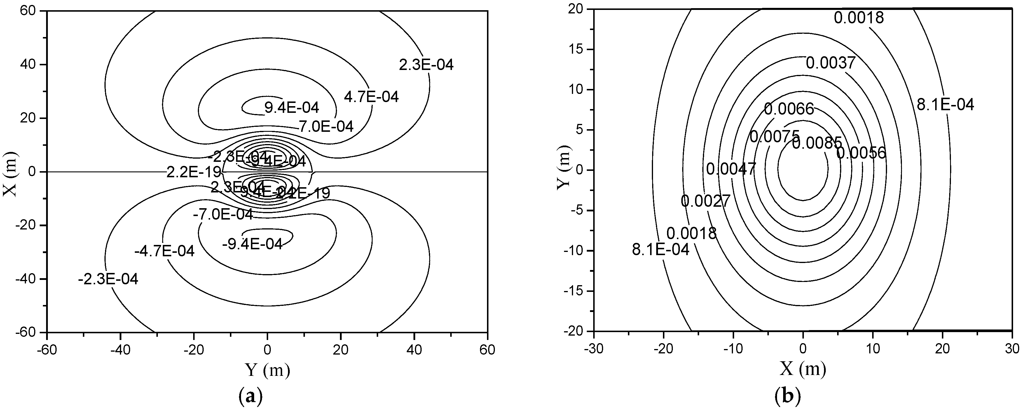
4.4. Quantitative Analysis of Frictional Force fs

As the characteristic of shell friction fs between the shield and the soil is like that between pile and soil, slip softening phenomenon should be considered in calculation of fs by Equation (15) [38,39,40]. Based on Equations (9) and (10) and the integral region in Figure 11, the displacement of fs can be calculated like fd above.
{ f s = β s σ θ tan δ σ θ = σ V sin 2 θ + σ H cos 2 θ
where βs is slip softening coefficient; σθ is radial stress; δ is interface friction angle; σV is vertical stress; σH is horizontal stress.
As we can see from Figure 12a,b, the ground settlement is symmetrically distributed along the Y axis, ground uplifts in front of the cutter head, settlements behind the cutter head. The horizontal displacement is symmetrically distributed along the diagonal line of X axis and Y axis.

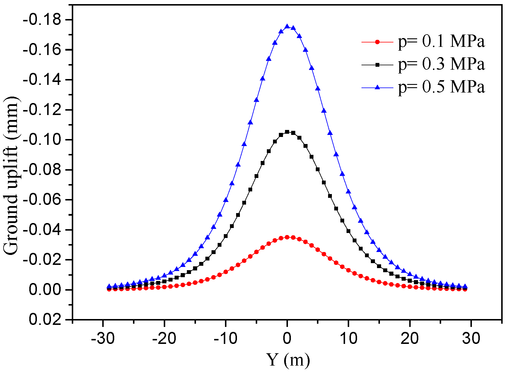
4.5. Quantitative Analysis of Synchronous Grouting Pressure p

Synchronized grouting at the shield tail can fill the shield tail gap in time and reduce ground loss, but on the other hand, the grouting will extrude the surrounding soil. The extrusion action can be obvious with poor water permeability and high grouting pressure, which may cause stratum uplift.
In practice, the distribution pattern of synchronous grouting pressure is complex. In order to simplify the calculation, the following assumptions are made: the grouting pressure distributes uniformly in the circumference; little slurry diffuses into surrounding stratum in a short time, that is, the force on stratum is the same as grouting pressure; the longitudinal length of grouting is taken as 1 m [41]. Based on Equations (9) and (10) and the integral region in Figure 13, the displacement of p can be calculated. As we can see from Figure 14 and Figure 15, the displacement values and distribution range are small. It is worth noting that ground uplift increases significantly with the increase of grouting pressure in Figure 16, so grouting pressure needs to be selected reasonably.

5. Verification by Field Monitoring Data

The stratum displacements induced by various effect factors and total displacement are shown in Table 3. The effect ratio of ground loss is over 95%, which plays a decisive role. The ratios to total of frictional force fd and fs are much less than 1%; they are too small to be considered. The ratios of additional thrust q and synchronous grouting pressure p are a little larger, but are no more than 3%. As shown in Figure 8 and Figure 16, the variations of these two factors make some small quantitative changes, but no qualitative differences. It shows that this conclusion has good universality for different working conditions. The total ground settlement is compared with field monitoring data in Figure 17. From this, we can see that there are some differences between them. For example, the calculating settlement maximum is 10.25 mm, while monitoring data is 9.7 mm. The difference rate is 5.3%, which belongs to acceptable error range. What is more, they have the same trend and the difference is stable. This is because that the elastic model is adopted in this paper, but in practice with the redistribution of stress, a pressure arch will be formed around the tunnel. The soil out of the arch is prevented from entering the loosening zone, which cause the field monitoring data to be slightly smaller than theoretical calculation result.

6. Conclusions

In order to relieve the increasing ground traffic pressure in the process of urbanization in China, it is inevitable to build more metro lines. The evaluation and control of the stratum displacement is a prominent problem during shield construction of city metro engineers. Based on the engineering project of an interval tunnel between Shizishan Station and Chuanshi Station in Chengdu Metro Line 7, China, this paper analyzed the action mechanism of stratum displacement induced by shield tunneling, and divided effect factors into two categories: ground loss factors and mechanical factors. Through the quantitative analysis of the effect factors, the following conclusions can be drawn:
(1).
The calculation results of this paper are applicable for shield tunneling in urban soft soil layer, but the calculation methods and thoughts have a good universality for different working conditions, it just needs necessary parameter adjustments. Combining the advantages of Loganathan method and mirror source-sink method, the three-dimensional displacement induced by ground loss are calculated. Based on the elastic half-space Mindlin model, the displacement at any point induced by four mechanical effect factors through coordinate transformation and different integral region is deduced. The total displacement is the sum of the two, which is verified by field monitoring data. The difference is stable and the difference rate is about 5.3%. This is because that the elastic model is adopted in this paper, but in practice with the redistribution of stress, a pressure arch will be formed around the tunnel. The soil out of the arch is prevented from entering the loosening zone, which causes the field monitoring data to be slightly smaller than theoretical calculation result. It is a methodological flaw, not a statistical one, and needs to be solved in future.
(2).
The displacement induced by ground loss is over 95% of the total displacement, which plays a decisive role. The key to controlling stratum disturbance is decreasing the ground loss. When the outer diameter of shield and segment is determined, the most effective measure is decreasing the strain of grouting layer. As the stratum uplift caused by grouting pressure is much smaller than the settlement caused by grouting layer strain, the grouting pressure or grouting volume can be increased appropriately to ensure the grouting filling rate.
(3).
The ratio of displacement caused by mechanical effect factors to total displacement is too small (less than 5%), even far less than the error caused by various simplified assumptions in theoretical calculation. In practice, this part of the displacement cannot be separated from the total displacement, it is difficult to verify its accuracy and validity by numerical simulation or field monitoring. Therefore, it is suggested that in calculation, the mechanical effect factors can be neglected as appropriate, and only the displacement caused by ground loss is considered, which can not only reduce the computational complexity and make it easy to use, but also can meet the requirements of engineering application accuracy.

Author Contributions

Y.Z. wrote the article; L.C. provided the parameters of project; H.Z. carried out the calculations and analyzed the calculation results; P.T. processed the field data; S.C. offered some useful suggestions for the preparation.

Funding

The study was supported by the National Natural Science Foundation of China (NSFC) under Grant No. 51508037.

Acknowledgments

We also highly appreciate the contribution of data collection from China Railway No. 9 Group Co., Ltd. Finally, the authors would like to thank reviewers for useful comments and editors for improving the manuscript.

Conflicts of Interest

The authors declare no conflict of interest.

References

  1. Zhang, H.; Chen, L.; Zhu, Y.; Zhou, Z.; Chen, S. Stress Field Distribution and Deformation Law of Large Deformation Tunnel Excavation in Soft Rock Mass. Appl. Sci. 2019, 9, 865. [Google Scholar] [CrossRef]
  2. Zhu, Y.; Chen, L.; Zhang, H.; Zhou, Z.; Chen, S. Physical and Mechanical Characteristics of Soft Rock Tunnel and the Effect of Excavation on Supporting Structure. Appl. Sci. 2019, 9, 1517. [Google Scholar] [CrossRef]
  3. Zeng, Y.H.; Liu, K.; Fang, Y.; Zhang, X.F.; Bai, Y. Fire Model Test on Temperature Field in the Rescue Station of an Extralong Railway Tunnel. Adv. Civ. Eng. 2019, 1–12. [Google Scholar] [CrossRef]
  4. Zhang, H.; Chen, L.; Chen, S.; Sun, J.; Yang, J. The spatiotemporal distribution law of microseismic events and rockburst characteristics of the deeply buried tunnel group. Energies 2018, 11, 3257. [Google Scholar] [CrossRef]
  5. Lin, F.; Chen, S.G.; Zhang, H. Study on type selection of shield equipment in different geological conditions. In Green Building, Materials and Civil Engineering; CRC Press: Boca Raton, FL, USA, 2014; pp. 409–412. [Google Scholar]
  6. Zhou, Z.L.; Chen, S.G.; Li, Y.S. Research on predicting and distribution of stratum displacement of double–tube parallel shield tunnel. J. Highw. Transp. Res. Dev. 2015, 32, 109–117. [Google Scholar]
  7. Zou, J.F.; Qian, Z.H.; Xiang, X.H.; Chen, G.H. Face Stability of a tunnel excavated in saturated nonhomogeneous soils. Tunn. Undergr. Space Technol. 2019, 83, 1–17. [Google Scholar] [CrossRef]
  8. Zhang, H.; Chen, S.G.; Deng, X.F. Analysis of the influence of shield driving parameters on ground settlements. Mod. Tunn. Tech. 2010, 47, 48–53. [Google Scholar]
  9. Liao, S.M.; Liu, J.H.; Wang, R.L.; Li, Z.M. Shield tunneling and environment protection in Shanghai soft ground. Tunn. Undergr. Space Technol. 2009, 24, 454–465. [Google Scholar] [CrossRef]
  10. Xie, X.Y.; Yang, Y.B.; Mei, J. Analysis of ground surface settlement induced by the construction of a large–diameter shield–driven tunnel in Shanghai, China. Tunn. Undergr. Space Technol. 2016, 51, 120–132. [Google Scholar] [CrossRef]
  11. Zhang, H.; Chen, S.G.; Tan, X.R. Research on the mechanical behavior of a segment of a shield tunnel adjacent to a pile foundation. Mod. Tunn. Tech. 2012, 49, 101–107. [Google Scholar]
  12. Zhang, H.; Chen, S.G.; Deng, X.F. Analysis on influence of shield tunneling on ground and bridge pile. Chin. J. Underg. Sp. Eng. 2011, 7, 552–557. [Google Scholar]
  13. Peck, R.B. Deep Excavations and tunnelling in soft ground. In Proceedings of the 7th International Conference on Soil Mechanics and Foundation Engineering, Mexico City, Mexico, 25–29 August 1969; Balkema A A: Rotterdam, The Netherlands, 1969; pp. 225–290. [Google Scholar]
  14. Celestino, T.B.; Gomes, R.A.M.; Bortolucci, A.A. Errors in group distortions due to settlement trough adjustment. Tunn. Undergr. Space Technol. 2000, 15, 97–100. [Google Scholar] [CrossRef]
  15. Vorster, T.E.B.; Klar, A.; Soga, K.; Mair, R.J. Estimating the effects of tunneling on existing pipelines. J. Geotech. Geoenviron. 2005, 131, 1399–1410. [Google Scholar] [CrossRef]
  16. Attewell, P.B.; Yeates, J.; Selby, A.R. Soil Movements Induced by Tunnelling and Their Effects on Pipelines and Structures; Thomson Science and Professional: 2nd Floor Aldgate House, 33 Aldgate High Street, London, UK, 1986. [Google Scholar]
  17. Osman, A.S.; Bolton, M.D.; Mair, R.J. Predicting 2D ground movement around tunnels in undrained clay. Geotech 2006, 56, 597–604. [Google Scholar] [CrossRef]
  18. New, B.M.; O’Reilly, M.P. Tunneling–induced ground movements, predicting their magnitude and effects. In Proceedings of the 4th Conference on Ground Movements and Structures; Pentech Press: London, UK, 1992; pp. 671–697. [Google Scholar]
  19. O’ Reilly, M.P.; New, B.M. Settlement above tunnels in the United Kingdom their magnitude and prediction. In Proceedings of the Tunneling’ 82 Symposium, London, UK, 7–11 June 1982; pp. 173–181. [Google Scholar]
  20. Sagaseta, C. Analysis of undrained soil deformation due to ground loss. Geotechnique 1987, 37, 301–320. [Google Scholar] [CrossRef]
  21. Loganathan, N.; Poulos, H.G. Analytical prediction for tunneling–induced ground movements in clays. J. Geotech. Geoenviron. 1998, 124, 846–856. [Google Scholar] [CrossRef]
  22. Federico, P.; Andrew, J.W. Ground movements due to shallow tunnels in soft ground: 1. analytical solutions. J. Geotech. Geoenviron. 2013, 140, 04013040. [Google Scholar]
  23. Kung, G.T.; Juang, C.H.; Hsiao, E.C.; Hashash, Y.M. Simplified model for wall deflection and ground–surface settlement caused by braced excavation in clays. J. Geotech. Geoenviron. 2007, 133, 731–747. [Google Scholar] [CrossRef]
  24. Peng, F.L.; Wang, H.L.; Tan, Y.X.; Zheng, L.; Li, Y.L. Field measurements and finite–element method simulation of a tunnel shaft constructed by pneumatic caisson method in shanghai soft ground. J. Geotech. Geoenviron. 2011, 137, 516–524. [Google Scholar] [CrossRef]
  25. Chakeri, H.; Ozcelik, Y.; Unver, B. Effects of important factors on surface settlement prediction for metro tunnel excavated by EPB. Tunn. Undergr. Space Technol. 2013, 36, 14–23. [Google Scholar] [CrossRef]
  26. Zhang, Z.G.; Huang, M.S. Geotechnical influence on existing subway tunnels induced by multiline tunneling in Shanghai soft soil. Comput. Geotech. 2014, 56, 121–132. [Google Scholar] [CrossRef]
  27. Son, M.; Cording, E.J. Estimation of building damage due to excavation–induced ground movements. J. Geotech. Geoenviron. 2005, 131, 162–177. [Google Scholar] [CrossRef]
  28. Ahmed, M.; Iskander, M. Analysis of tunneling–induced ground movements using transparent soil models. J. Geotech. Geoenviron. 2010, 137, 525–535. [Google Scholar] [CrossRef]
  29. Mindlin, R.D. Force at a point in the interior of a semiinfinite solid. Physics 1936, 7, 195–202. [Google Scholar] [CrossRef]
  30. Huang, M.S.; Zhang, C.R.; Li, Z. A simplified analysis method for the influence of tunneling on grouped piles. Tunn. Undergr. Space Technol. 2009, 24, 410–422. [Google Scholar] [CrossRef]
  31. Zhang, Z.G.; Huang, M.S.; Zhang, M.X. Theoretical prediction of ground movements induced by tunneling in multilayered soils. Tunn. Undergr. Space Technol. 2011, 26, 345–355. [Google Scholar] [CrossRef]
  32. Sun, H.S.; Lei, G.H.; Ng, C.W.W. Displacements under linearly distributed pressures by extended Mindlin’s equations. Comput. Geotech. 2013, 50, 143–149. [Google Scholar] [CrossRef]
  33. Antonio, B. Analytical solutions for shallow tunnels in saturated ground. J. Eng. Mech. 2001, 127, 1258–1266. [Google Scholar]
  34. Verruijt, A.; Booker, J.R. Surface settlements due to deformation of a tunnel in an elastic half plane. Geotechnique 1996, 46, 753–756. [Google Scholar] [CrossRef]
  35. Verruijt, A. Deformations of an elastic half plane with a circular cavity. Int. J. Solids Struct. 1998, 35, 2795–2804. [Google Scholar] [CrossRef]
  36. Lee, K.M.; Rowe, R.K.; Lo, K.Y. Subsidence owing to tunneling I: Estimating the gap parameter. Can. Geotech. J. 1992, 29, 929–940. [Google Scholar] [CrossRef]
  37. Zhang, Q.Q.; Li, S.C.; Li, L.P.; Chen, Y.J. Simplified method for settlement prediction of pile groups considering skin friction softing and end resistance hardening. Chin. J. Rock Mech. Eng. 2013, 32, 615–624. [Google Scholar]
  38. Potyondy, J.G. Skin friction between various soils and construction materials. Geotechnique 1961, 11, 339–353. [Google Scholar] [CrossRef]
  39. Alonso, E.E.; Josa, A.; Iedesma, A. Negative skin friction on Piles: A simplified analysis and prediction procedure. Geotechnique 1984, 34, 341–357. [Google Scholar] [CrossRef]
  40. Wang, H.X. Effect of cutterhead compressing the front soil and influence of head aperture ratio on contact pressure of EPB shield to the front soil. Chin. Civ. Eng. J. 2009, 42, 113–118. [Google Scholar]
  41. Li, Z.M.; Liao, S.M.; Dai, Z.R. Theoretical study on synchronous grouting filling patterns and pressure distribution of EPB shield tunnels. Chin. J. Geotech. Eng. 2010, 32, 1752–1757. [Google Scholar]
Figure 1. The diagram of shield tunneling in stratum.
Applsci 09 03028 g001
Figure 2. Counter map of ground settlement.
Applsci 09 03028 g002
Figure 3. Displacement of stratum: (a) Variation curve of settlement maximum; (b) Counter map of horizontal displacement.
Applsci 09 03028 g003
Figure 4. Four mechanical effect factors.
Applsci 09 03028 g004
Figure 5. Mindlin model. Where M (x, y, z) is any point in the infinite half space; P is a vertical concentrated load; Q is a horizontal concentrated load; d is the burial depth of concentrated load; R 1 = r 2 + ( z d ) 2 ; R 2 = r 2 + ( z + d ) 2 ; r = x 2 + y 2 .
Applsci 09 03028 g005
Figure 6. Coordinate transformation.
Applsci 09 03028 g006
Figure 7. Integral region of q.
Applsci 09 03028 g007
Figure 8. Longitudinal ground settlement caused by q.
Applsci 09 03028 g008
Figure 9. Horizontal displacement of stratum caused by q.
Applsci 09 03028 g009
Figure 10. Ground movements caused by fd: (a) Settlement; (b) Horizontal displacement.
Applsci 09 03028 g010
Figure 11. Integral region of fs.
Applsci 09 03028 g011
Figure 12. Ground movements caused by fs: (a) Settlement; (b) Horizontal displacement.
Applsci 09 03028 g012
Figure 13. Integral region of p.
Applsci 09 03028 g013
Figure 14. Ground uplift caused by p.
Applsci 09 03028 g014
Figure 15. Horizontal displacement of stratum caused by p.
Applsci 09 03028 g015
Figure 16. Ground uplift of different p.
Applsci 09 03028 g016
Figure 17. Total calculating displacement and field monitoring data.
Applsci 09 03028 g017
Table 1. Physical parameters of soil.
MaterialUnit Weight (kN/m3)Thickness (m)Poisson’s RatioCohesion (kPa)Friction AngleElastic Modules (MPa)
Topsoil202.10.34514°5.94
Intermediary weathered mudstone23.437.90.1730018°180
Table 2. Construction parameters of shield machine.
ParameterShield Tunneling Speed (mm/min)Rotation Speed of Cutter Head (r/min)Cutter Opening Ratio (%)Closure Number of CuttersDiameter of Shield (mm)
Value803.553646280
Length of Main Machine (mm)Diameter of Segment (mm)Synchronous Grouting Pressure (MPa)Strain Rate of Grouting Layer (%)Slip Softening CoefficientInterface Friction Angle (°)
842760000.38.40.96.5
Table 3. The displacements induced by various effect factors.
Effect FactorsGround Settlement Maximum (mm)Ratio to TotalHorizontal Displacement in Stratum (mm)Ratio to Total
q−0.120.010.200.03
fd<0.01<0.010.04<0.01
fs±0.04<0.010.03<0.01
p−0.180.020.100.01
Ground loss10.511.027.300.95
total10.251.007.671.00

