Abstract
An optical fiber sensing system integrating a fiber Bragg grating (FBG) sensor, a long-period fiber grating (LPFG) optical filter and a photodetector is presented to monitor the dynamic response of a structure subjected to base excitation and impact loading. The FBG sensor is attached to a test specimen and connected to an LPFG filter. As the light reflected from the FBG sensor is transmitted through the long-period fiber grating filter, the intensity of the light is modulated by the wavelength, which is affected by the strain of the FBG. By measuring the intensity of the light using a photodetector, the wavelength reflected from the FBG sensor can be demodulated, thus leading to the determination of the strain in the structure. To demonstrate its effectiveness, the proposed sensing system was employed to measure the dynamic strain of a beam subjected to mechanical testing. The mechanical tests comprised three load scenarios: base excitation by a shaker at resonant frequency, impact loading by a hammer and shock test on a drop table. To monitor the dynamic strain during the test and validate the accuracy of the measurement of the FBG sensor, strain gauge was used as reference. Experimental results show good correlation between the measurements of FBG sensor and strain gauge. The present work provides a fast response and easy-to-implement optical fiber sensing system for structural health monitoring based on real-time dynamic strain measurements.
1. Introduction
Sensing technologies for real-time monitoring of engineering structures are very important, since in-service monitoring can lead to the improved safety and performance of engineering structures. Traditional sensors such as the strain gauge and the load cell are mostly based on electrical working principles to measure physical quantities such as strain, force or temperature. The main drawbacks of these sensors can be attributed to the sensitivity, cross talk, non-compatibility with harsh environments and their sizes [1]. Optical fiber sensors with small size, light weight, good sensitivity, and that are easy to be surface bonded or embedded are considered ideal sensors for structure health monitoring. The most distinguished characteristics of the optical fiber sensor is its unique capability to act as both the sensing unit and light transmission medium, allowing data acquisition equipment to be installed away from the field [2]. Fiber Bragg grating (FBG) sensors based on reflecting particular wavelengths of light with the advantages of high accuracy, corrosion resistance and convenience in forming sensor networks have received extensive attention. Li et al. [3] proposed a new type of fiber Bragg grating sensor to monitor bridge cable force. Gao et al. [4] presented a highly sensitive and compact FBG sensor for simultaneous measurement of refractive index and temperature. Luyckx et al. [5] used FBG sensors to quantitatively measure multi-axial strain fields of cross-ply laminates loaded along the three principal mechanical axes. Mulle et al. [6] employed longitudinally and transversely embedded FBGs to monitor the hot-press molding process of glass-fiber-reinforced polypropylene (GFPP) laminates. Bai et al. [7] used two cascaded FBGs to measure both the acoustic and magnetic properties simultaneously. Zhao et al. [8] proposed a novel integrated optical fiber sensor for temperature, pressure and flow measurements. Mieloszyk and Ostachowicz [9] demonstrated the capability of embedded FBG sensors in adhesive bonded composite materials for the detection of moisture contamination. Vendittozzi et al. [10] investigated the effect of metal coating thickness on the temperature sensitivity of FBG sensor from cryogenic to room temperature.
The effect of vibration on engineering structures caused by various phenomena can have serious consequences for their strength and safety. Staino et al. [11] reported that vibration was considered one of the major concerns with respect to structural and mechanical failure, resulting in a significant reduction in the operational efficiency and life cycle of wind turbines. Adhesively bonded joints are commonly employed in automobile, aerospace and civil structures. The strength of joints and dynamic properties of the bonded structure can be severely weakened and affected by vibrating loads [12]. Blade fatigue induced by vibration is one of the most common causes of failures in gas turbines, reported to be up to 42% of total gas turbine failures [13]. Civil engineering structures such as high-rise buildings and suspension bridges are especially susceptible to the vibration due to the earthquake or high wind loads [14]. Vibrations not only result in the fatigue and failure of engineering structures, but also induce wear, tear and noise pollution [15]. To explore the vibrating behavior of structures, a reliable sensor for accurate measurement of the vibration is essential. Vibration sensors can be used for monitoring the conditions of rotating machinery, such as overheating, inadequate lubrication, excessive loading or bearing wear [16]. A variety of sensors are employed for the measurement of a vibrating structure. Among them, strain gauges can be used to measure either strain or vibrational amplitude [17], and a gyroscope was employed to determine rotation angle or angular velocity [18], while a laser vibrometer was used to detect bending and torsional displacements [19]. There is one major drawback for all these sensors. A lumped mass is introduced into the structure due to the incorporation of the sensor. This may alter the structural integrity and dynamic properties of the structure [20]. In contrast, FBG sensors with small size and light weight cannot introduce a notable effect on the vibrational characters of structures. Chuang et al. [21] proposed a displacement sensing system using FBG sensor to experimentally measure the dynamic and transient responses of a phononic crystal (PC) beam subjected to impact loading. Jin et al. [20] measured the flow-induced vibrations using fiber-optic grating sensors. Jang and Kim [22] presented a methodology of impact-induced delamination assessment using FBG sensor. Li et al. [23] investigated the temperature sensitivity of FBG sensors coated with metals during a dynamic cooling process. Davis and Kersey [24] presented an interrogation technique based on a wavelength division coupler to detect the wavelength shift of FBG sensor. Hung et al. [25] integrated the FBG and LPFG to form a novel optical fiber sensing system for real-time gas detection. Jorge et al. [26] reviewed optical fiber sensing configurations and interrogation techniques including FBG, LPFG, micro-interferometers, multimode interference for refractive index measurement. Ng and Chiang [27] investigated the thermal effects on the transmission spectra of LPFGs both theoretically and experimentally. Tripathi et al. [28] developed a temperature insensitive refractive-index sensor using two concatenated dual-resonance LPFGs. Liao et al. [29] proposed an interrogation method integrated FBG sensor with Mach-Zehnder interferometer for simultaneous measurements of refractive index and temperature. Cao et al. [30] employed the FBG sensor incorporation with Sagnac loop to measure the temperature and refractive index simultaneously. Park et al. [31] demonstrated real-time monitoring of a dynamic FBG strain sensor for structural health monitoring using a Fourier-domain mode-locked (FDML) fiber laser. Zou et al. [32] measured dynamic strain using two wavelength-matched FBG sensors interrogated with a cascaded LPFG. Zou and Dong [33] used a tunable twin-core fiber as an edge filter to demodulate the FBG sensor for temperature measurement. Li et al. [34] proposed an interrogation system for FBG sensing based on the InGaAs linear image sensor. Recently, Micro Electro-Mechanical System (MEMS) accelerometers have received a lot of attention for structural health monitoring in civil engineering applications [35]. Such sensors are considered to demonstrate high portability and durability with a limited cost. Cigada et al. [36] and Sun et al. [37] presented comparative experimental studies of a cost ratio of MEMS accelerometers in comparison with traditional piezoelectric accelerometers. Benevicius et al. [38] employed MEMS accelerometers for the dynamic measurements of human body motions. Jimenez et al. [39] used MEMS accelerometers to monitor the vibration of smart machine rotors. However, the cost of FBG sensors is higher than that of electric strain gauges. Nevertheless, the advantages of FBG, such as immunity to electromagnetic interference, suitability for applications in multiplexed and distributed system, capability for long-distance transmission, and better resolution and sensitivity in comparison with the strain gauge provide an alternative choice for users, in particular for applications in structural health monitoring.
In this study, the fiber Bragg grating sensor is integrated with a long-period fiber grating (LPFG) filter and a photodetector to measure the transient and vibration responses of structures subjected to a variety of mechanical testing. The mechanical tests comprised three load scenarios: base excitation by a shaker at resonant frequency, impact loading by a hammer, and shock test on a drop table. The dynamic strain measured by the fiber Bragg grating sensor is validated with the strain gauge. Good agreement between the two sensors demonstrates the capability of FBG sensor in measuring the transient and vibration responses of the structures. The aim of the present work is to develop a fast response and easy-to-implement optical fiber sensing system for structural health monitoring based on real time dynamic strain measurements.
2. Optical Fiber Sensing System
An FBG sensor is formed when a spatially periodic modulation of the core refractive index along a single-mode fiber is created by exposing the optical fiber to an ultraviolet laser beam. As a broadband optical source impinges upon Bragg gratings, a narrow-band spectral peak is reflected, and all other wavelengths are transmitted without change, resulting in a dip in the transmitted spectrum, as shown in Figure 1.
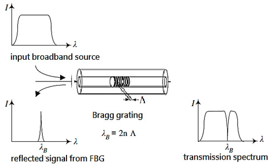
Figure 1.
Transmission and reflectance spectrum from fiber Bragg grating.
The Bragg wavelength reflected from the FBG sensor is related to the grating period and the effective refractive index , as follows:
An FBG sensor with a constant grating period and refractive index will reflect light at a single Bragg wavelength. Change in the grating period and index of refraction due to the strain and temperature will lead to a shift of the Bragg wavelength. At a constant temperature, the load-induced Bragg wavelength shifts for the light propagating along the two eigenaxes are described by Sirkis [40] using the following equations:
where are the principal strains in the optical fiber and represents the axial direction; and are the strain-optic Pockel’s constants. When the transverse strains are equal and related to the longitudinal strains by the Poisson’s ratio of the optical fiber, i.e., . Equation (2a,b) become equivalent, leading to a single Bragg wavelength shift as follows.
This shows that FBG sensors are wavelength-modulated sensors. Using Equation (3), the longitudinal strain in the sensor can be determined by the measured Bragg wavelength shift.
Long-period fiber gratings (LPFG) are formed by introducing a periodic modulation of the refractive index with a grating period on the order of hundreds of microns along the core of a single-mode fiber. LPFG can couple the fundamental guided core mode to the forward propagating cladding modes of a fiber. Since the coupling is wavelength-selective, LPFG acts as a wavelength-dependent band stop filter. For the band stop filter, the largest rejection ratio is its resonance peak wavelength. The resonance peak wavelength of an LPFG can be determined using the phase matching condition as follows [41]:
where and are the effective indices of the core and cladding, respectively; is the grating period. The transmission spectrum of the LPFG used in this study is the 5th coupling mode, as shown in Figure 2.
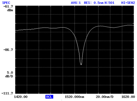
Figure 2.
Transmission spectrum of LPFG filter.
A wavelength meter is commonly used to detect the wavelength. However, the slow response of the wavelength meter is not suitable for dynamic and transient measurements. In this work, the shift of the FBG wavelength is converted to the change of the light intensity measured by a photodetector. The quick response of the photodetector—within microseconds—can be used to measure the dynamic and transient responses. The interrogation scheme for the Bragg wavelength of the FBG sensor is based on a matched LPFG. The principle of using a matched LPFG to interrogate the signal encoded by the Bragg wavelength from a FBG sensor is based on the measurement of the optical intensity. A schematic diagram of the integrated optical fiber sensing system is shown in Figure 3. The optical system consists of a broadband light source, 2 × 1 coupler, FBG sensor, LPFG optical filter and a photodetector. When the light of a broadband spectrum is guided through the optical fiber to the FBG, a narrow band of Bragg wavelength is reflected back from the FBG sensor. In this work, LPFG is used as an optical filter to convert the wavelength shift of the FBG into a change of light intensity. The light intensity is transferred to a voltage signal through a photodetector, leading to the determination of the strain applied to the FBG sensor.
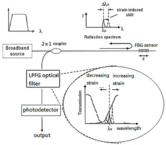
Figure 3.
Schematic diagram of the integrated optical fiber sensing system.
3. Strain-Induced Light Intensity Variation
It is well known that the resonant wavelength of LPFG can be affected by the temperature. To compensate the temperature, Ng et al. [42] proposed a model that mounted a bent LPFG on a beam with a suitable thermal expansion coefficient. The effect of temperature on the resonance wavelength of LPFG can be significantly reduced. An alternate method to compensate the temperature effect on the LPFG was reported by Ng and Chiang [27]. The temperature sensitivity of LPFG can be eliminated by balancing the thermo-optic coefficients of the fiber core and cladding. In this work, LPFG is connected with FBG in series. FBG is attached onto the structure subjected to mechanical loading. LPFG is free standing and kept in the environment with constant temperature to avoid the influence of the temperature on the resonant wavelength of LPFG. The shift of Bragg wavelength induced by the strain in the FBG sensor is converted to the change of the light intensity through an LPFG filter. The light intensity is measured by a photodetector and recorded in the voltage signal. To calibrate the relationship between the strain and the light intensity, experimental tests of a cantilever beam subjected to a loading at its free end were conducted. In the middle of the cantilever beam, an FBG sensor and a strain gauge were adhered to the top and bottom surfaces, respectively. The reflected Bragg wavelength () of the FBG sensor used in this study without applied strain is shown in Figure 4. The center wavelength of the FBG is located in the right half of LPFG band filter (as shown in Figure 2). Thus, the light intensity is increases linearly with the increase in strain. A schematic diagram of FBG-LPFG spectra is illustrated in Figure 5. The cantilever beam is made of copper with Young’s modulus and density of 120 GPa and , respectively. The length, width and thickness of the beam are 0.285 m, 0.02 m and 0.001 m, respectively. The cantilever beam is loaded at its free end with various displacements ranging from 5 mm to 30 mm. The strain (measured by strain gauge) and light intensity (measured by photodetector) are recorded and plotted in Figure 6. Three tests were conducted to demonstrate the reproducibility. The results show a linear relationship between the strain and light intensity variation as follows.
where light intensity variation is normalized by , the light intensity is reflected from the FBG sensor without applied strain.
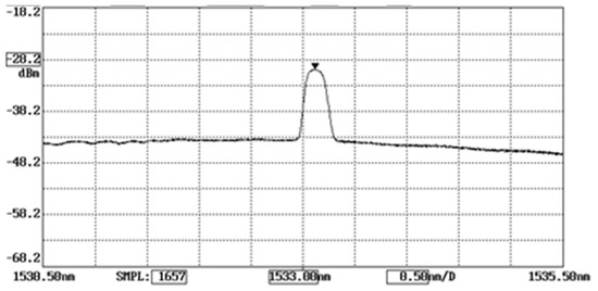
Figure 4.
Wavelength of FBG sensor.
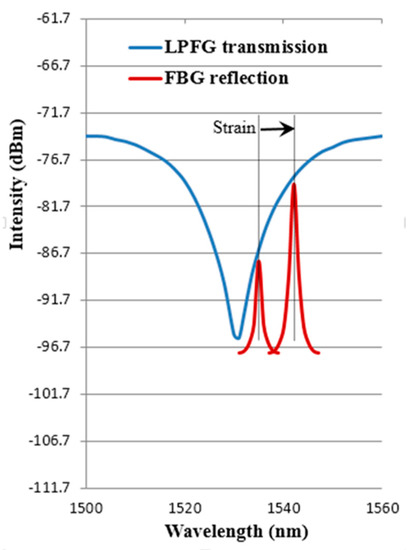
Figure 5.
Schematic diagram of FBG-LPFG spectra.
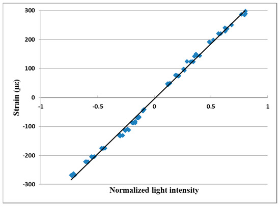
Figure 6.
Relation between the strain and normalized light intensity.
A good linear correlation between the strain and light intensity variation with standard deviation of 2.7% demonstrates that the proposed optical fiber sensing system can be used to detect the strain by measuring the light intensity through a photodetector. The proposed FBG sensing system consists of FBG, LPFG and photodetector. The sensitivity and resolution of the sensing system are dependent on the characteristic of these sensing units. In this work, the sensitivities of FBG and LPFG are and 3.25 dBm/nm, respectively, while the responsivity of photodetector (EOT 3010, Electro-Optic Technology, Inc., Traverse City, MI, USA) is 1.1 A/W at 1550 nm. Experimental tests showed that the sensitivity of the proposed sensing system is , which is close to the results (3) reported by Davis and Kersey [24] using the demodulation technique based on a wavelength division coupler. The optical fiber sensing system is fast response, easy to implement, and capable of monitoring the transient and vibration responses of a structure.
4. Shock and Vibration Tests
To validate the accuracy of the optical fiber sensor, experimental tests were conducted by subjecting a beam to base excitation, impact and drop tests. In the following tests, the FBG sensor is attached on a cantilever beam subjected to bending. The bending strain can be transferred from the beam to the FBG sensor, resulting in a shift of the Bragg wavelength reflected from the FBG sensor. The bending strain in the cantilever is position dependent. The main influence exerted by the position of the FBG in the cantilever beam is that the strain of the FBG varies with the position of the FBG on the beam. In this work, the FBG sensor was placed at the center of the beam. The effects of bending on the FBG include strain-induced wavelength shift and curvature-induced power loss. In this work, the bending curvature of the cantilever is small; therefore, the power loss can be neglected.
4.1. Base Excitation
The beam is the same as in the previous section. The clamped end is connected to a shaker, as shown in Figure 7, which makes the beam vibrate. The shaker is able to excite the test specimen with four different frequencies simultaneously. The natural frequency of a cantilever beam can be determined by using the following equations.
where βi is the solution of Equation (6a); ρ, E, A, L, and I represent the density, Young’s modulus, cross-section area, length and moment of inertia of the cantilever beam, respectively.
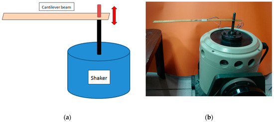
Figure 7.
Base excitation test on a cantilever beam. (a) schematic diagram; (b) experimental setup.
The first five natural frequencies calculated from Equation (6) for the cantilever beam are 7.37 Hz, 46.21 Hz, 129.39 Hz, 253.63 Hz and 419.23 Hz, respectively. In the following tests, the cantilever beam is subjected to base excitation with various frequencies.
4.1.1. Single Frequency Base Excitation
The cantilever beam is excited by a shaker with a frequency of 7 Hz, which is approximate to the first natural frequency of 7.37 Hz. An FBG sensor is attached at the center of the cantilever beam. Once the light intensity reflected from the FBG sensor has been measured, we then extract the strain using Equation (5). The strain measured by the FBG sensor is compared with the result of strain gauge as shown in Figure 8. It shows that a good agreement is achieved with an average difference of 3.7%. The same experimental test was conducted by Her and Yang [43]. The vibrational response was measured using a Mach-Zehnder interferometric optical sensor, as shown in Figure 9. It can be observed that a reasonable agreement is obtained between the FBG sensor and Mach-Zehnder interferometric optical sensor.
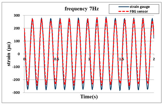
Figure 8.
Vibrational response of a cantilever beam subjected to single frequency base excitation.
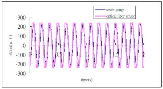
Figure 9.
Vibrational response measured by Mach-Zehnder interferometric optical sensor [43].
4.1.2. Dual Frequency Base Excitation
The cantilever beam is excited by a shaker with two different frequencies—46 Hz and 50 Hz—simultaneously. Figure 10 plots the vibrational response of the cantilever beam subjected to base excitation with dual frequencies. The chirp effect can be observed in the dynamic response since the dual frequencies are close to each other. A large difference is observed in the transient period due to a small strain. The sensitivity of the FBG sensor is 5 better that of the strain gauge with a resolution of 10 . Thus, the dynamic strain measured by the proposed FBG sensor is more accurate than the strain gauge. In the steady oscillation with large strain, the dynamic response measured by the FBG sensor is in good agreement with the strain gauge. The average difference between the FBG and strain gauge is 10.6%.
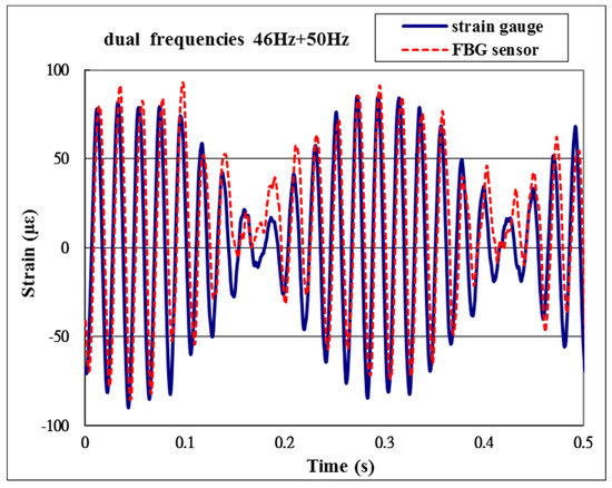
Figure 10.
Vibrational response of a cantilever beam subjected to dual frequencies base excitation.
4.2. Impact Test
The cantilever beam is impacted by a hammer, as shown in Figure 11. The dynamic strains of the cantilever beam measured by the FBG and strain gauge are plotted in Figure 12. It can be observed that the transient responses measured by the FBG sensor are in close agreement with the results measured by the strain gauge. The average difference between the FBG and strain gauge is 4.7%. The frequency response of the cantilever beam can be obtained by taking the fast Fourier transform (FFT) of the time response as shown in Figure 13. The natural frequencies (7.47 Hz and 46.98 Hz) deduced from the frequency response are in good agreement with the theoretical prediction (7.37 Hz and 46.21 Hz) using Equation (6).
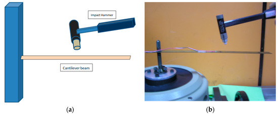
Figure 11.
Cantilever beam impacted by a hammer. (a) schematic diagram; (b) experimental setup.
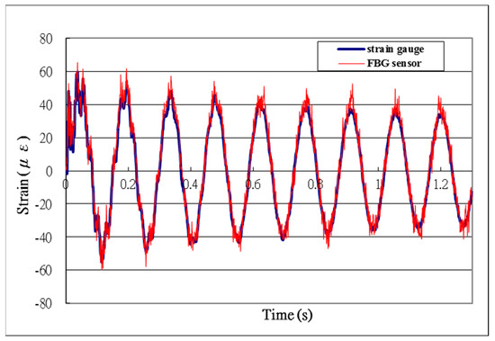
Figure 12.
Transient response of a cantilever beam subjected to impact loading.
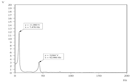
Figure 13.
Frequency responses of the cantilever beam (x: frequency; y: amplitude).
4.3. Drop Test
The free-fall drop table (model DP-1200-60, King Ton Inc., New Taipei City, Taiwan), as shown in Figure 14, was employed to perform the drop test. The impact impulse exerted on the test specimen by the drop table can be adjusted using different target materials. There are three different types of impact impulses, including half sine pulse, square pulse and trapezoid pulse, provided by the drop table. In this work, the half sine impulse was adopted through the use of four half-spheres of Teflon as the target material, as shown in Figure 15. The test specimen made of copper is fixed on the drop table through a steel fixture. The two ends of the beam are clamped on the fixture. Between the beam and the drop table, there is a 20 mm standoff to allow beam bending. The table was dropped from a height of 300 mm along the four guiding rods onto four half-spheres of Teflon. An accelerometer was attached on the drop table to measure the acceleration response of the table during the drop test. The acceleration of the drop table shown in Figure 16 indicates that the beam was subjected to a half sine impulse during the drop test. The transient response of the beam was measured by both the strain gauge and FBG sensor as shown in Figure 17. It can be observed that the strain measured by the FBG sensor is in a good agreement with the strain gauge. The average difference between the FBG and strain gauge is 4.2%. This demonstrates that the FBG sensor is capable of monitoring the transient response of a structure subjected to shock and impact loadings.
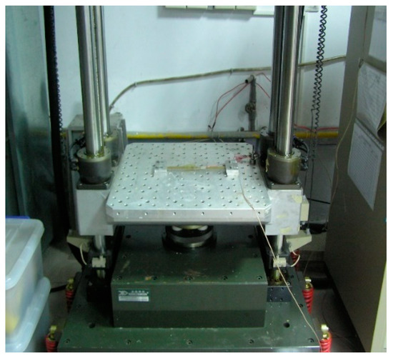
Figure 14.
Free-fall drop table.
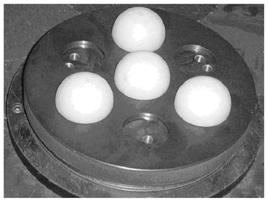
Figure 15.
Four half-spheres served as the impact target.
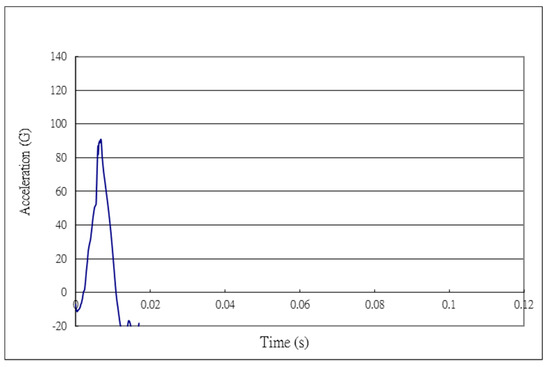
Figure 16.
Acceleration of the drop table.
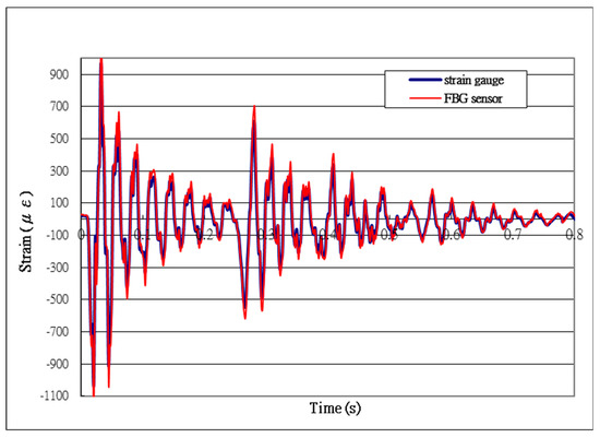
Figure 17.
Transient response of a beam subjected to the drop test.
5. Conclusions
Fiber Bragg grating sensors have been proved to be well suited to structure health monitoring over conventional electrical sensors with the capability of multiplexed strain measurements. In this work, an optical fiber sensing system consisting of an FBG sensor, an LPFG filter, and a photodetector was successfully utilized to measure the transient and vibration responses of a structure subjected to shock and vibration loadings. The shift of wavelength reflected from the fiber Bragg grating sensor induced by the applied strain is converted to a light intensity variation through a long period fiber grating optical filter. Strain measurements of a beam subjected to base excitation, drop and impact tests were presented and the results were validated with the output of strain gauge. The present study demonstrates that dynamic strain measurements using the FBG sensor integrated with an LPFG optical filter and a photodetector can be used to monitor the transient and vibration responses of structures. The aim of the present work is to provide a fast-response and easy-to-implement sensing system for structural health monitoring based on real-time dynamic strain measurements. The experimental setup and measuring technique presented in this study are simple and easy to implement. It is helpful and useful in terms of the practical applications in industry.
Author Contributions
Conceptualization, S.-C.H.; Methodology, S.-C.C.; Validation, S.-C.C.; Formal analysis, S.-C.H.; Investigation, S.-C.H.; Writing—Original draft preparation, S.-C.H.; Writing—Review & editing, S.-C.H.; Visualization, S.-C.C.; Supervision, S.-C.H.; Project administration, S.-C.H.; Funding acquisition, S.-C.H.
Funding
This research was funded by Ministry of Science and Technology of the R.O.C grant number MOST 107-2221-E-155-029 and The APC was funded by Ministry of Science and Technology of the R.O.C.
Conflicts of Interest
The authors declare no conflict of interest.
References
- Hoe, B.V.; Lee, G.; Bosman, E.; Missinne, J.; Kalathimekkad, S.; Maskery, O.; Webb, D.J.; Sugden, K.; Daele, P.V.; Steenberge, G.V. Ultra Small Integrated Optical Fiber Sensing System. Sensors 2012, 12, 12052–12069. [Google Scholar]
- Wang, J.-N.; Tang, J.-L. Feasibility of Fiber Bragg Grating and Long-Period Fiber Grating Sensors under Different Environmental Conditions. Sensors 2010, 10, 10105–10127. [Google Scholar] [CrossRef] [PubMed]
- Li, X.X.; Ren, W.X.; Bi, K.M. FBG force-testing ring for bridge cable force monitoring and temperature compensation. Sens. Actuators A Phys. 2015, 223, 105–113. [Google Scholar] [CrossRef]
- Gao, S.; Zhang, W.; Zhang, H.; Geng, P.; Lin, W.; Liu, B.; Bai, Z.; Xue, X. Fiber modal interferometer with embedded fiber Bragg grating for simultaneous measurements of refractive index and temperature. Sens. Actuators B Chem. 2013, 188, 931–936. [Google Scholar] [CrossRef]
- Luyckx, G.; Voet, E.; Lammens, N.; De Waele, W.; Degrieck, J. Residual strain-induced birefringent FBGs for multi-axial strain monitoring of CFRP composite laminates. NDT E Int. 2013, 54, 142–150. [Google Scholar] [CrossRef]
- Mulle, M.; Wafai, H.; Yudhanto, A.; Lubineau, G.; Yaldiz, R.; Schijve, W.; Verghese, N. Process monitoring of glass reinforced polypropylene laminates using fiber Bragg gratings. Compos. Sci. Technol. 2016, 123, 143–150. [Google Scholar] [CrossRef]
- Bai, X.; Hu, M.; Gang, T.; Rong, Q. Simultaneous acoustic and magnetic measurement using cascaded fibre Bragg grating. Opt. Fiber Technol. 2018, 45, 376–382. [Google Scholar] [CrossRef]
- Zhao, Q.; Zheng, H.K.; Lv, R.Q.; Gu, Y.F.; Zhao, Y.; Yang, Y. Novel integrated optical fiber sensor for temperature, pressure and flow measurement. Sens. Actuators A Phys. 2018, 280, 68–75. [Google Scholar] [CrossRef]
- Mieloszyk, M.; Ostachowicz, W. Moisture contamination detection in adhesive bond using embedded FBG sensors. Mech. Syst. Signal Process. 2017, 84, 1–14. [Google Scholar] [CrossRef]
- Vendittozzi, C.; Felli, F.; Lupi, C. Modeling FBG sensors sensitivity from cryogenic temperatures to room temperature as a function of metal coating thickness. Opt. Fiber Technol. 2018, 42, 84–91. [Google Scholar] [CrossRef]
- Staino, A.; Basu, B.; Nielsen, S. Actuator control of edgewise vibrations in wind turbine blades. J. Sound Vib. 2012, 331, 1233–1256. [Google Scholar] [CrossRef]
- Pang, J.; Du, Y.; Wu, K.; Hu, P.; Li, W. Fatigue analysis of adhesive joints under vibration loading. J. Adhes. 2013, 89, 899–920. [Google Scholar] [CrossRef]
- Madhavan, S.; Jain, R.; Sujatha, C.; Sekhar, A. Vibration based damage detection of rotor blades in a gas turbine engine. Eng. Fail. Anal. 2014, 46, 26–39. [Google Scholar] [CrossRef]
- Rama Mohan Rao, A.; Sivasubramanian, K. Optimal placement of actuators for active vibration control of seismic excited tall buildings using a multiple start guided neighborhood search (MSGNS) algorithm. J. Sound Vib. 2008, 311, 133–159. [Google Scholar] [CrossRef]
- Sharma, S.K.; Gaur, H.; Kulkarni, M.; Patil, G.; Bhattacharya, B.; Sharma, A. PZT–PDMS composite for active damping of vibrations. Compos. Sci. Technol. 2013, 77, 42–51. [Google Scholar] [CrossRef]
- Zook, J.; Herb, W.R.; Bassett, C.; Stark, T.; Schoess, J.N.; Wilson, M.L. Fiber-optic vibration sensor based on frequency modulation of light-excited oscillators. Sens. Actuators A Phys. 2000, 83, 270–276. [Google Scholar] [CrossRef]
- Andjelic, M.; Popp, K. Stability effects in a normal triangular cylinder array. J. Fluids Struct. 1989, 3, 165–185. [Google Scholar] [CrossRef]
- Bhadbhade, V.; Jalili, N.; Mahmoodi, S.N. A novel piezoelectrically actuated flexural/torsional vibrating beam gyroscope. J. Sound Vib. 2008, 311, 1305–1324. [Google Scholar] [CrossRef]
- Trethewey, M.; Sommer, H.; Cafeo, J. A dual beam laser vibrometer for measurement of dynamic structural rotations and displacements. J. Sound Vib. 1993, 164, 67–84. [Google Scholar] [CrossRef]
- Jin, W.; Zhou, Y.; Chan, P.; Xu, H. A fibre-optic grating sensor for the study of flow-induced vibrations. Sens. Actuators A Phys. 2000, 79, 36–45. [Google Scholar] [CrossRef]
- Chuang, K.C.; Yuan, Z.W.; Guo, Y.; Lv, X.F. A self-demodulated fiber Bragg grating for investigating impact-induced transient responses of phononic crystal beams. J. Sound Vib. 2018, 431, 40–53. [Google Scholar] [CrossRef]
- Jang, B.W.; Kim, C.G. Real-time estimation of delamination occurrence induced by low-velocity impact in composite plates using optical fiber sensing system. Compos. Struct. 2018, 189, 455–462. [Google Scholar] [CrossRef]
- Li, Y.; Yang, K.; Li, X. Temperature sensing characteristics of metal coated FBG during dynamic cooling process. Opt. Fiber Technol. 2018, 45, 368–375. [Google Scholar] [CrossRef]
- Davis, M.; Kersey, A. All-fibre Bragg grating strain-sensor demodulation technique using a wavelength division coupler. Electron. Lett. 1994, 30, 75–77. [Google Scholar] [CrossRef]
- Hung, S.S.; Chang, H.C.; Chang, I.N. A Portable Array-Type Optical Fiber Sensing Instrument for Real-Time Gas Detection. Sensors 2016, 16, 2087. [Google Scholar] [CrossRef]
- Jorge, P.A.S.; Silva, S.O.; Gouveia, C.; Tafulo, P.; Coelho, L.; Caldas, P.; Viegas, D.; Rego, G.; Baptista, J.M.; Santos, J.L.; et al. Fiber Optic-Based Refractive Index Sensing at INESC Porto. Sensors 2012, 12, 8371–8389. [Google Scholar] [CrossRef]
- Ng, M.N.; Chiang, K.S. Thermal effects on the transmission spectra of long-period fiber gratings. Opt. Commun. 2002, 208, 321–327. [Google Scholar] [CrossRef]
- Tripathi, S.M.; Bock, W.J.; Kumar, A.; Mikulic, P. Temperature insensitive high-precision refractive-index sensor using two concatenated dual-resonance long-period gratings. Opt. Lett. 2013, 38, 1666–1668. [Google Scholar] [CrossRef]
- Liao, C.R.; Wang, Y.; Wang, D.N.; Yang, M.W. Fiber In-Line Mach–Zehnder Interferometer Embedded in FBG for Simultaneous Refractive Index and Temperature Measurement. IEEE Photonics Technol. Lett. 2010, 22, 1686–1688. [Google Scholar] [CrossRef]
- Cao, Y.; Zhang, H.; Miao, Y.; Ma, Z.; Li, B. Simultaneous measurement of temperature and refractive index based on microfiber Bragg Grating in Sagnac loop. Opt. Fiber Technol. 2019, 47, 147–151. [Google Scholar] [CrossRef]
- Park, J.; Kwon, Y.S.; Ko, M.O.; Jeon, M.Y. Dynamic fiber Bragg grating strain sensor interrogation with real-time measurement. Opt. Fiber Technol. 2017, 38, 147–153. [Google Scholar] [CrossRef]
- Zou, H.; Liang, D.; Zeng, J. Dynamic strain measurement using two wavelength-matched fiber Bragg grating sensors interrogated by a cascaded long-period fiber grating. Opt. Lasers Eng. 2012, 50, 199–203. [Google Scholar] [CrossRef]
- Zou, Y.; Dong, X. Demodulation of the FBG temperature sensor with the tunable twin-core fiber. Microw. Opt. Technol. Lett. 2011, 53, 81–84. [Google Scholar] [CrossRef]
- Li, G.; Zhang, H.; Liu, B.; Zhang, J.; Yuan, S.; Kai, G.; Dong, X. The interrogation system for FBG sensing based on the InGaAs linear image sensor. Microw. Opt. Technol. Lett. 2008, 50, 1101–1104. [Google Scholar] [CrossRef]
- Bedon, C.; Bergamo, E.; Izzi, M.; Noè, S. Prototyping and Validation of MEMS Accelerometers for Structural Health Monitoring—The Case Study of the Pietratagliata Cable-Stayed Bridge. J. Sens. Actuator Netw. 2018, 7, 30. [Google Scholar] [CrossRef]
- Cigada, A.; Lurati, M.; Redaelli, M.; Vanali, M. Mechanical Performance and Metrological Characterization of MEMS Accelerometers and Application in Modal Analysis. In Proceedings of the IMAC XXV International Modal Analysis Conference, Orlando, FL, USA, 19–22 February 2007; pp. 236–244. [Google Scholar]
- Sun, Z.; Chen, D.; Chen, J.; Deng, T.; Li, G.; Xu, C.; Wang, J. A MEMS Based Electrochemical Seismometer with Low Cost and Wide Working Bandwidth. Procedia Eng. 2016, 168, 806–809. [Google Scholar] [CrossRef]
- Benevicius, V.; Ostaševičius, V.; Gaidys, R. Identification of capacitive MEMS accelerometer structure parameters for human body dynamics measurements. Sensors 2013, 13, 11184–11195. [Google Scholar] [CrossRef]
- Jiménez, S.; Cole, M.O.; Keogh, P.S. Vibration sensing in smart machine rotors using internal MEMS accelerometers. J. Sound Vib. 2016, 377, 58–75. [Google Scholar] [CrossRef]
- Sirkis, J.S. Unified approach to phase-strain-temperature models for smart structure interferometric optical fiber sensors: Part 1, development. Opt. Eng. 1993, 32, 752. [Google Scholar] [CrossRef]
- Falate, R.; Frazão, O.; Rego, G.; Fabris, J.L.; Santos, J.L. Refractometric sensor based on a phase-shifted long-period fiber grating. Appl. Opt. 2006, 45, 5066–5072. [Google Scholar] [CrossRef]
- Ng, M.N.; Chen, Z.; Chiang, K.S. Temperature compensation of long-period fiber grating for refractive-index sensing with bending effect. IEEE Photonics Technol. Lett. 2002, 14, 361–362. [Google Scholar]
- Her, S.C.; Yang, C.M. Dynamic strain measured by Mach-Zehnder interferometric optical fiber sensors. Sensors 2012, 12, 3314–3326. [Google Scholar] [CrossRef] [PubMed]


© 2019 by the authors. Licensee MDPI, Basel, Switzerland. This article is an open access article distributed under the terms and conditions of the Creative Commons Attribution (CC BY) license (http://creativecommons.org/licenses/by/4.0/).