Article

DC-Microgrid Operation Planning for an Electric Vehicle Supply Infrastructure

Department of Electrical and Information Engineering, Politecnico di Bari, 70125 Bari, Italy
*
Author to whom correspondence should be addressed.
Appl. Sci. 2019, 9(13), 2687; https://doi.org/10.3390/app9132687
Submission received: 15 May 2019 / Revised: 19 June 2019 / Accepted: 30 June 2019 / Published: 1 July 2019
(This article belongs to the Special Issue Intelligent Energy Management of Electrical Power Systems)

Abstract

:
The integration of electric vehicles (EVs) in power systems can be encouraged by charging station diffusion. These stations can perform smart charging processes, and can take advantage of the involvement of distributed generation sources in a microgrid framework. Furthermore, since photovoltaic batteries and EVs are sources based on direct current (DC), the realization of a DC microgrid structure is promising, though challenging. In this paper, a mixed-integer linear procedure for determining optimal operation planning of a DC-based electric vehicle supply infrastructure is proposed. The procedure aims at optimizing daily operational costs, based on forecast of photovoltaic production and EV exploitation. Peculiar aspects of energy storage devices and of the DC microgrid framework are accounted for through a non-linear iterative procedure. The proposed approach is applied to a test DC microgrid on different operation days and its effectiveness is compared to non-linear formulation solved by means of a genetic algorithm.

1. Introduction

The diffusion of electric vehicles (EVs) is likely to experience a sharp increase, as predicted by several studies and scenario evaluations of transport and energy stakeholders. In particular, power system operators are guided by several policies aimed at reducing the environmental impact of transport [1].
A remarkable support to EV diffusion is given by technological improvements. The newest battery technologies ensure pocket-size units and the ability to provide a longer duration of travel and for wider distances to be covered. For charging stations, the interchangeability has been improved thanks to connector standardization [2], while the realization of more powerful plug systems helps reduce waiting times. Although EV intelligence controls the charging process to preserve battery life, the electric grid operator is rather interested in controlling the EV charge in order to reduce the counter-effects caused by massive requests at limited intervals and concentrated in specific locations. Thus, the concept of smart charging has gained significant ground [3,4], and the communication ability between EVs and the power system has remarkably improved. In this sense, for EV smart charge to have effects on the power system, the figure of the EV aggregator is introduced [5].
In order to improve the positive interactions with the power system, the integration of EV charging stations with distributed generation (DG) facilities based on renewables is a field of interest for industry and research [6]. In fact, the combined operation with DG can ensure renewable energy supply to EVs, reducing grid power purchases. Moreover, the addition of energy storage devices can improve the exploitation of local sources by EVs, even in the absence of temporal synchronization [7]. This coordinated control of different sources is one of the most promising uses for the development of smart microgrids for EV needs.
Furthermore, since photovoltaic systems, batteries for EVs, and local storage are based on direct current (DC), they can easily constitute DC microgrids [8,9]. DC microgrids represent an interesting development of the power industry, since they ensure high controllability and cause less problems with respect to alternating-current power system integration (e.g., inertia and frequency, reactive power), although the development of DC systems with increasing sizes and voltage levels is still challenging. Moreover, EV connection to DC microgrids opens the field to efficient vehicle-to-grid (V2G) applications, enabling EV bidirectional energy exchanges analogous to storage devices when parked.
One of the functions of a DC microgrid controller is the operational programming, which is called upon to elaborate, with suitable advance notice (generally on daily basis), the optimal power setpoints of all controllable devices, according to inputs (renewable source and load forecast, EV usage for mobility, economic parameters) and taking into account device technical limitations. After this stage, the real time operation control is aimed at verifying the correct DC microgrid function that is able to sustain possible the variation of inputs or other unplanned events (e.g., unintentional islanding) [10,11]. In the framework of day-ahead operation programming of microgrids, including EVs, different approaches are found in the literature.
In some works, EV charging duration and intensity are considered as known inputs in programming procedures. In particular, in one previous study [12] a stochastic generation of plug-in hybrid EV usage is exploited in an optimal management model solved with the modified symbiotic organism search (MSOS) algorithm and compared with the genetic algorithm (GA) on two test systems. Another study [13] includes charging station features in the determination of EV charging scenarios in mixed-integer linear programming (MILP) microgrid optimization. Moreover, in another study [14] network theory for managing EVs is embedded in a complex energy hub (involving AC and DC, as well as thermal and cooling parts) aimed at determining optimal bidding through risk measures. In another study [15], EV charging is a random variable in a robust optimization approach based on MILP.
Other papers focus on EV controllable charge. In one study [16], the operation of microgrid components, including EVs, is determined by solving a non-linear programming problem with the objectives of minimum cost, emissions, and load variation, comparing a standard particle swarm optimization algorithm with advanced ones. In another study [17], maximum revenue and maximum EV requirement satisfaction are compared as objectives for EV management in a smart city environment. In another study [18], a model based on Poisson distribution of EV arrivals is embedded in a robust optimization approach. Finally, a sequential energy management strategy procedure involving either smart charging or immediate charge in a DC microgrid, including only EV stations, is described in a previous study [19].
A performance comparison of EV charge and V2G in day-ahead operation planning for minimum grid exchange in a microgrid is proposed in a previous study [20], considering different EV models and drawing suitable indicators. In another study [21], the effects of an EV management strategy exploiting load variation in a microgrid for placing charge and discharge actions is investigated. In another study [22], the optimization of a microgrid with or without EVs able to perform V2G and demand response is carried out considering operational costs and EV battery degradation costs.
With regard to V2G approaches, in a previous study [23] a minimum-cost objective is posed, considering reserve constraints in a MILP environment with EV priority according to forecast use, whereas in another study [24] a function including costs, battery degradation, and energy (not supplied estimation) is considered, involving a transformation of AC load flow relations and a solution with a modified bat algorithm. In another study [25], the influence of V2G in a multi-energy microgrid with different EV users is considered by accounting for EV aggregators. In another study [26] the effect of uncertainty is shown by stochastic scenarios of EV and load in a microgrid optimization procedure with AC load flow decoupling, reporting sensibilities on parameter variation. In one study [27] a Monte-Carlo selection of best results of optimal operation is carried out by means of proper fitness functions, exploiting a GA solution. In another study [28], two different approaches are exploited in the presence of accurate or inaccurate EV usage forecasting, involving optimization versus multi-agent auctions. In one study [29] a multi-objective procedure, including cost and power fluctuations, is proposed, accounting for different EV operation modes and drawing V2G incentives using a multi-stage memetic algorithm to find a solution. The energy management for EV integration in a workplace microgrid with a multi-agent optimization scheme is described in a previous study [30].
Photovoltaic (PV) powered EV station programming is dealt with in a previous study [31], modeling different attitudes to smart charging of EVs. In another study [32], a DC microgrid with PV and EV charging stations is proposed, including cost and energy circulation of batteries, and solved with non-dominated sorting genetic algorithm (NSGA-II). In another study [33], an optimization model, including cost and an EV preference indicator, is considered for a system including PV, storage, and EVs with V2G. In another study [34], optimized control of an EV station integrated with PV and storage is proposed, involving contracts with EVs, battery degradation, and unsupplied demand costs with AC load flow. Stochastic dynamic programming for an EV station, including PV, storage, and fuel cells, is reported in one study [35], comparing this with deterministic programming. Authors of a previous study [36] account for stochastic estimation of PV and EV parking in the day-ahead method, adding a real time model for predictive control.
Energy management of a DC microgrid presents peculiar aspects and functions, as reported by previous authors [37,38,39]. In-line with this framework, a general control structure is illustrated in a previous study [40]. In another study [41], an optimization model with voltage network constraints is depicted, whereas semidefinite programming is exploited in a previous study [42] to deal with non-linear features. A simplified linear model of DC microgrid for integration in optimal bidding procedure with risk measures is proposed in another study [43]. In one study [44], a procedure based on fuzzy logic is embedded in real-time power control of a DC microgrid, whereas real time optimal power management of a DC microgrid is adopted in another study [45]. Real-time control of a DC microgrid based on dynamic models is proposed in other studies [46,47].
Among various approaches investigated in the literature, a limited focus is devoted to specific aspects of DC microgrids when V2G is enabled. In particular, in operation programming, few details are given on economic relations with EVs and on actual operational features of converters.
In this paper, a mixed-integer linear procedure for determining optimal operation planning of an electric vehicle supply infrastructure structured as a DC microgrid is proposed. The procedure aims at optimizing daily operational cost, including the viewpoint of a microgrid operator and EV owners, according to predictions of PV production and EV utilization for mobility needs. A set of indicators of EV usage is drawn. The proposed approach is applied to a test DC microgrid on different days of operation and its effectiveness is compared to non-linear formulation solved by means of a genetic algorithm.
The main contributions of the proposed approach can be synthesized as follows:
-
A model of degradation costs and capacity for energy storage devices is included;
-
Specific features of active power losses in DC microgrids and in converters are taken into account;
-
The economic objective involves a microgrid and an EV aggregator;
-
An iterative procedure is exploited in order to consider non-linear realistic models and keep linear programming properties;
-
Performance indicators related to EV exploitation for electric system integration are adopted to prove procedure validity.
The paper is organized as follows. In Section 2 the proposed methodology is illustrated, according to the nomenclature reported in the appendix, along with a reference non-linear approach. In Section 3 the test system is described, while the performed tests and remarkable indices are discussed in Section 4. Conclusions are presented in Section 5.

2. Methodology

2.1. General Assumptions

The optimization procedure for DC microgrid day-ahead programming is based on Mixed-Integer Linear Programming (MILP) and it is aimed at determining the power exchange plan for each device at each timestep. The state variable vector x can be defined as follows:
x = [ x r e T , x i n t T ] T ,
where x r e includes all real variables and x i n t all integer ones; the superscript T stands for transpose.
As for the sizing method described in a previous study [48], the model is supposed to be applied to a DC microgrid, including a photovoltaic plant, N b storage systems, and N e v electric vehicles, usually operated in grid connected mode. In this framework, power exchange levels pertaining to each component in each timestep represent the real state variables, encompassed in the vector x r e with dimensions ( ( 3 N b + 3 N e v + 2 ) N t ) × 1 , as follows:
x r e = [ ( P g i n ) T , ( P g o u t ) T , ( P b c ) T , ( P b d ) T , ( S b ) T , ( P e v c ) T , ( P e v d ) T , ( S e v ) T ] T ,
where P g i n and P g o u t are N t × 1 vectors of P g i n ( t ) and P g o u t ( t ) , respectively, whereas P b c , P b d , and S b are ( N b N t ) × 1 vectors of P i c ( t ) , P i d ( t ) , and S i ( t ) , respectively, and P e v c , P e v d , and S e v are ( N e v N t ) × 1 vectors of P j c ( t ) , P j d ( t ) , and S j ( t ) , respectively.
The vector x i n t includes binary variables aimed at defining the direction of power exchanges in each timestep, and has a total dimension of ( ( N b + N e v + 1 ) N t ) × 1 :
x i n t = [ v g T , v b T , v e v T ] T .
where v g is the N t × 1 vector of v g ( t ) , v b is the ( N b N t ) × 1 vector of v i ( t ) , and v e v is the ( N e v N t ) × 1 vector of v j ( t ) , respectively.

2.2. Mixed Integer Linear Problem Formulation

The general formulation of the MILP problem is reported in Equation (4), where f ( x ) is the linear objective function, A and b are the coefficient matrix and the known term vector of the inequality constraints, respectively; A e q and b e q are the coefficient matrix and the known term vector of the equality constraints, respectively; x _ and x ¯ , respectively, are the lower and upper boundary vectors of the state variables:
min x f ( x ) s . t . { A x b A e q x = b e q x _ x x ¯
In order to determine the optimal power value for each component, the proposed methodology aims at minimizing net cost of microgrid operation in a combined viewpoint, including the microgrid operator and the EV owners [25]. Therefore, the objective function is defined as follows:
f ( x ) = Δ T t = 1 N t { c g ( t ) P g i n ( t ) r g ( t ) P g o u t ( t ) + i = 1 N b w i ( P i c ( t ) + P i d ( t ) ) +    + j = 1 N e v [ ( w j r j ( t ) ) P j d ( t ) + ( w j + c j ( t ) ) P j c ( t ) ] }
where the first two terms represent the cost for energy purchase and the revenue for power delivery at the grid connection point, whereas the third term accounts for the wearing cost of storage systems associated with both charge and discharge. The last term in Equation (5) is linked to EVs, and takes into account proper wearing costs, the revenue for EV discharge, and the cost for EV charge, considering the presence of an intermediate entity between EVs and the microgrid.
Many of the unitary costs in Equation (5) are defined by proper tariff schemes. The wearing cost of storage system w i is defined as a function of the maximum number of cycles Φ i at the desired level of depth-of-discharge D O D i [49], as per the following expression:
w i = ( 1 Φ i , 0 1 Φ i ) K i ,
where K i is the purchasing and installation cost of the i-th storage system and Φ i , 0 is the maximum number of cycles at the full discharge rate. The degradation cost of EV batteries w j is defined in the same way.
The following constraints hold:
P g i n ( t ) v g ( t ) P ¯ g t ,
P g o u t ( t ) ( 1 v g ( t ) ) P ¯ g t ,
P i c ( t ) v i ( t ) P ¯ i c i , t ,
P i d ( t ) ( 1 v i ( t ) ) P ¯ i d i , t ,
P j c ( t ) v j ( t ) P ¯ j c j , t ,
P j d ( t ) ( 1 v j ( t ) ) P ¯ j d j , t ,
0 P g i n ( t ) P ¯ g t ,
0 P g o u t ( t ) P ¯ g t ,
0 P i c ( t ) P ¯ i c i , t ,
0 P i d ( t ) P ¯ i d i , t ,
S _ i ( t ) S i ( t ) S ¯ i ( t ) i , t ,
0 P j c ( t ) P ¯ j c j , t ,
0 P j d ( t ) P ¯ j d j , t ,
S _ j ( t ) S j ( t ) S ¯ j ( t ) j , t ,
[ h g ( t ) ( 1 α g ( t ) ) ] P g i n ( t ) [ 1 h g ( t ) ( 1 + α g ( t ) ) ] P g o u t ( t ) + + i = 1 N b [ [ h i ( t ) ( 1 α i ( t ) ) ] P i d ( t ) [ 1 h i ( t ) ( 1 + α i ( t ) ) ] P i c ( t ) ] + + j = 1 N e v [ [ h j ( t ) ( 1 α j ( t ) ) ] P j d ( t ) [ 1 h j ( t ) ( 1 + α j ( t ) ) ] P j c ( t ) ] + + [ h P V ( t ) ( 1 α P V ( t ) ) ] P P V ( t ) = 0    t
S i ( t ) = S i ( t 1 ) + η i c ( t ) P i c ( t ) Δ T 1 η i d ( t ) P i d ( t ) Δ T ρ i Δ T i , t [ 0 , 1 ] ,
S i ( 0 ) = S i i n i i ,
S i ( N t ) = S i ( 0 ) i ,
S j ( t ) = S j ( t 1 ) + η j c ( t ) P j c ( t ) Δ T 1 η j d ( t ) P j d ( t ) Δ T ρ j Δ T Δ S j ( t ) j , t ,
S j ( 0 ) = S j i n i j ,
S j ( N t ) = S j ( 0 ) j .
In particular, Equations (7) and (8) are inequality constraints imposing the unidirectional power flow at the grid connection (either withdrawal or injection) for each timestep. Analogous formulations are assumed for charge and discharge power of storage devices in Equations (9) and (10) and of EVs in Equations (11) and (12). Moreover, Equations (13) and (14) represent the operating limits of power exchange at point of common coupling, and Equations (15)–(17) impose boundaries on charge power, discharge power, and state-of-charge (SOC) of storage. In Equation (17), battery SOC limits are a function of time, due to a proper model of capacity reduction depending on battery aging. Residual capacity of the i-th battery at time t E i ( t ) can be determined from nominal capacity E i n o m as a function of the total number of cycles experienced by the battery in its operation lifetime until the selected interval φ i ( t ) , as follows [50]:
E i ( t ) = E i n o m a i exp ( b i φ i ( t ) ) ,
where coefficients a i and b i depend on the selected battery type. The number of cycles φ i ( t ) , which is kept lower than Φ i to avoid replacement, is related to battery charge and discharge, depending on the imposed depth-of-discharge D O D i . Therefore, in Equation (17), S ¯ i ( t ) = E i ( t ) and S _ i ( t ) = E i ( t ) D O D i .
Analogously to batteries, EV exploitation limits are imposed by Equations (18)–(20), accounting for aging as well, although the upper limits of charge and discharge power are null for the expected EV driving intervals.
The equality constraint in Equation (21) ensures the power balance at common DC bus described in Equation (21). In this equation, parameters h and α represent inverter efficiency and cable losses coefficient, respectively, for the connection of devices indicated by the subscripts. Moreover, the update of SOC is imposed, respecting initial and final values, written for batteries in Equations (22)–(24) and for EVs in Equations (25)–(27). In particular, Δ S j ( t ) represents the amount of energy exploited for mobility by the j-th EV at the t-th time step, determined according to proper forecast. The value of Δ S j ( t ) is generally not null, only in EV driving intervals.
Some parameters, such as the converter efficiency, storage efficiency, storage capacity, and cable losses, show a non-linear dependence on the operating point of the device, which can be defined by the exchanged active power. In order to account for these features in the proposed MILP formulation, an iterative methodology is proposed, as sketched in Figure 1. In particular, the methodology starts from the vector u 0 of initial values of parameters (e.g., nominal efficiency, battery capacity of the previous day), and by solving the MILP problem in Equation (4) the initial solution x 0 is obtained. Therefore, the methodology includes, for each iteration k, the update of parameter vector u k (e.g., through proper efficiency curves) and a new solution of the MILP problem in Equation (4), obtaining the state variable vector at k-th iteration x k using u k . A convergence criterion is placed on the difference of the problem solution, determined as the sum of absolute values of differences of each component of the solution vector between two iteration steps, which does not have to overcome a specified threshold ε .
At the end of the analysis, the number of cycles experienced throughout the day by storage devices φ i ( N t ) and EVs φ j ( N t ) , along with relevant values of residual capacity S i ( N t ) and S j ( N t ) , respectively, are determined in order to serve as the starting point for the analysis of the next day.

2.3. Reference Non-Linear Approach

In order to prove the validity of the proposed MILP-based approach, the solutions and algorithm performance will be compared with a non-linear formulation. In this case, the state variables vector x includes only real state variables x r e , and integer variables are discarded. However, constraints involving the integer variables in the MILP problem are reformulated in a non-linear way, so that blocks in Equations (7) and (8), Equations (9) and (10), and Equations (11) and (12) are replaced by the following expressions in Equations (29), (30), and (31), respectively.
P g i n ( t ) P g o u t ( t ) = 0 t ,
P i c ( t ) P i d ( t ) = 0 i , t ,
P j c ( t ) P j d ( t ) = 0 j , t .
Moreover, the microgrid balance in Equation (21) and SOC update relations in Equations (22) and (25) become non-linear equality constraints, since the non-linearity of parameters—the inverter efficiency, storage efficiency, and cable loss coefficient—is dealt with through proper polynomial convex functions of the operating condition of each device.

3. System under Study

The proposed MILP-based algorithm and the reference non-linear formulation are applied to evaluate the optimal scheduling of the DC microgrid proposed as the backbone of the Electric Vehicle Supply Infrastructure (EVSI). The EVSI is a modular solution integrating renewable sources and storage for intelligent charging processes of EVs [51]. As introduced in a previous study [52], its structure includes a common DC bus, where all devices are interfaced with proper converters.
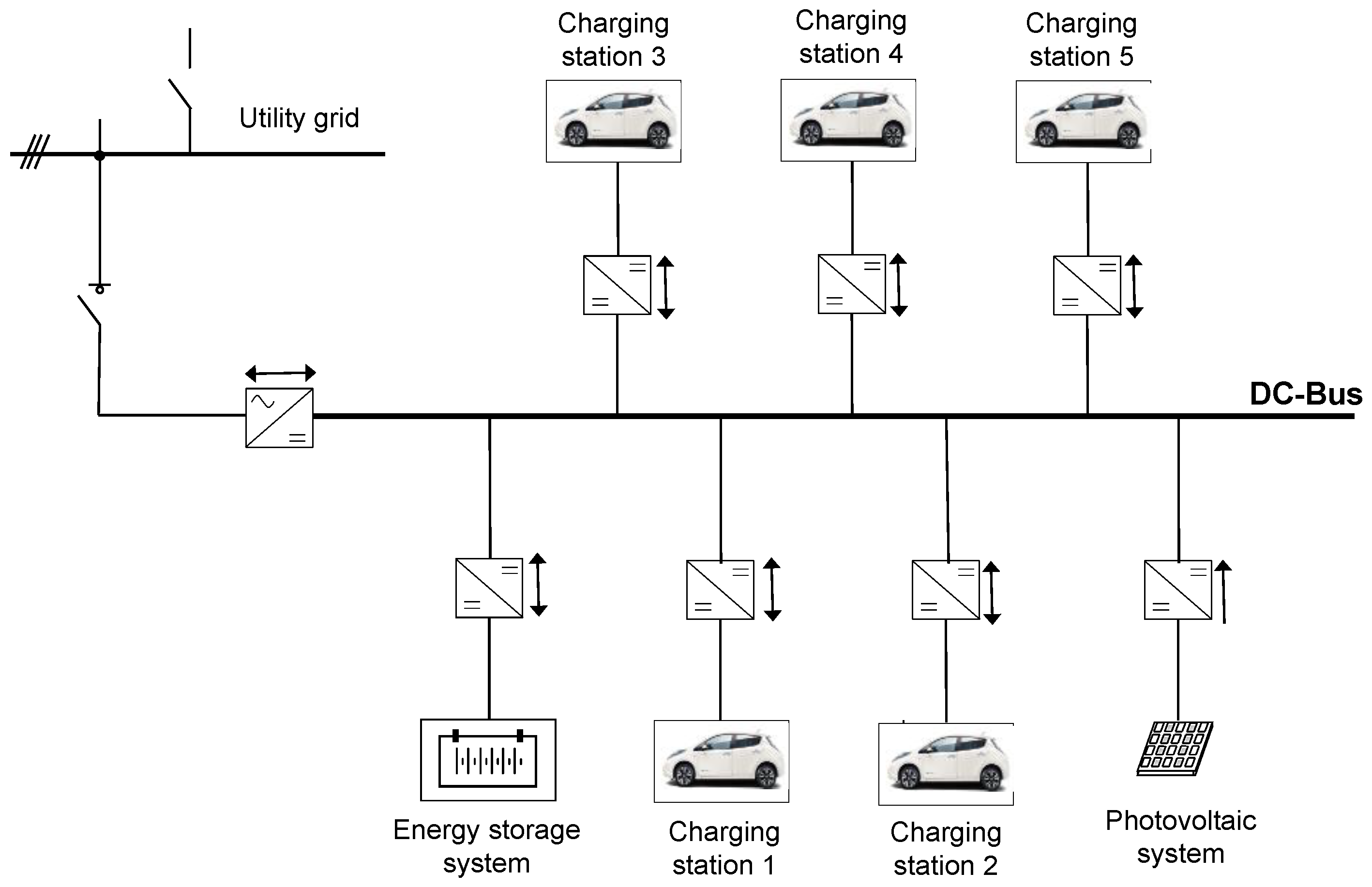
In particular, the DC microgrid under study comprises a PV plant, including polycrystalline modules, an energy storage system (ESS) based on Li-Ion batteries, a connection with the AC utility grid, and five charging stations for vehicles, according to the scheme reported in Figure 2. A bidirectional AC/DC converter is exploited to connect the utility grid and the EVSI, while six different bidirectional DC/DC converters connect the ESS and the EVs to the DC bus. Additionally, a unidirectional DC/DC converter interfaces the PV system.
The DC microgrid test case is aimed to reproduce the conditions to be realized in the framework of Bari Port Authority, Italy. Table 1 shows the installed sized for the DC microgrid devices, determined according to a proper sizing procedure as developed in a previous study [48], with a further increase in PV and ESS size to improve the reliability of the system.
With regard to the operating range of the devices, a variation between maximum capacity and 20% of capacity is assumed for EVs, whereas the limits are more stringent for the ESS (95% maximum, 25% minimum) in order to take into account an energy reserve that can be used for further regulation services in real time.

4. Tests and Results

The proposed procedure is implemented in MatLAB2015b® environment, considering 96 time steps of 15-minutes duration within each day. In particular, the optimization tool intlinprog is exploited to solve the proposed iterative MILP. Simulations are carried out on a workstation HP Z440 equipped with an Intel Xeon 3.50 GHz processor with 16 GB RAM.
The MILP problem-solving starts from the solution of the linear relaxed problem (without integer constraints on variables) according to the interior-point method. Then, a cut generation is used to restrict the linear solution, and finally, the branch-and-bound technique is adopted to generate two subproblems using proper heuristics and to evaluate the most suitable solution according to the best projection on improving lower or upper bounds [53]. As for the settings, the relative tolerances of the integer and non-integer variables are set to 0.0001 and 0.001, respectively.
Regarding non-linear problems, classical solution techniques are highly dependent on initial condition, since local solutions can be found instead of global ones. To overcome this issue, a metaheuristic approach, such as the genetic algorithm, can be exploited to generate and compare multiple solutions. In the following, the reference non-linear problem is, therefore, solved by means of the optimization tool ga in MatLAB framework.
The solution starts from the initial population in the first run of the linearized problem and further feasible populations up to 100 individuals are created in the feasible space. The fitness of individuals is, therefore, evaluated according to the Augmented Lagrangian function to account for non-linear constraints [54], and exploiting square root of rank as a fitness measure. Therefore, the next generation is given for 80% by crossover, where the selection of parents is based on Roulette heuristic, whereas 20% of individuals comes from mutation. Each process is governed by a Gaussian distribution with feasibility region adaption. The feasibility tolerance with respect to non-linear constraints is set to 0.001, and the maximum objective function tolerance is set to 0.001.

4.1. Test Cases: Different Operation Days

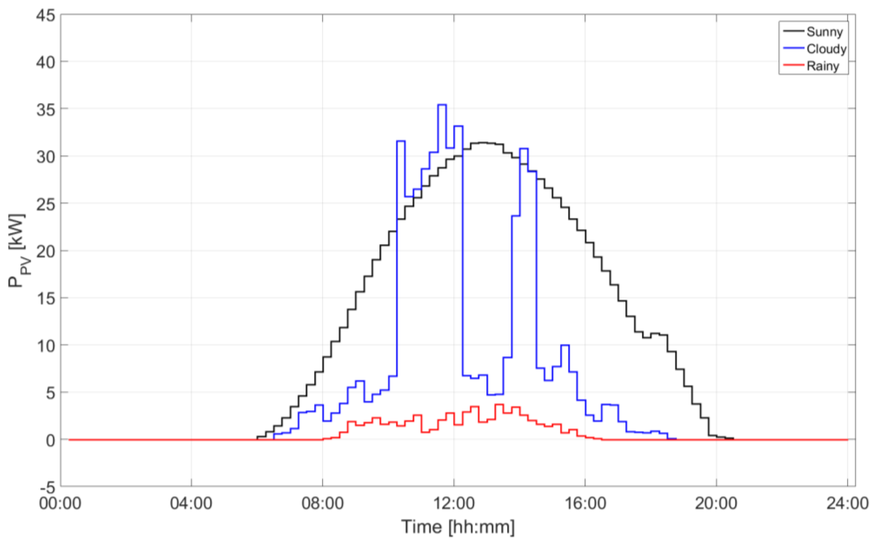
The proposed approach is tested for three typical days: a sunny day, a cloudy day, and a rainy day. These conditions are estimated according to historical data of a weather station close to the envisaged microgrid location [55]. Each day is affected by different availability of solar radiation, determined on the horizontal plane according to a proper forecast procedure, therefore power production level P P V ( t ) is estimated according to the Liu-Jordan model of solar radiation [56] and PV panel efficiency. The resulting trends are reported in Figure 3.
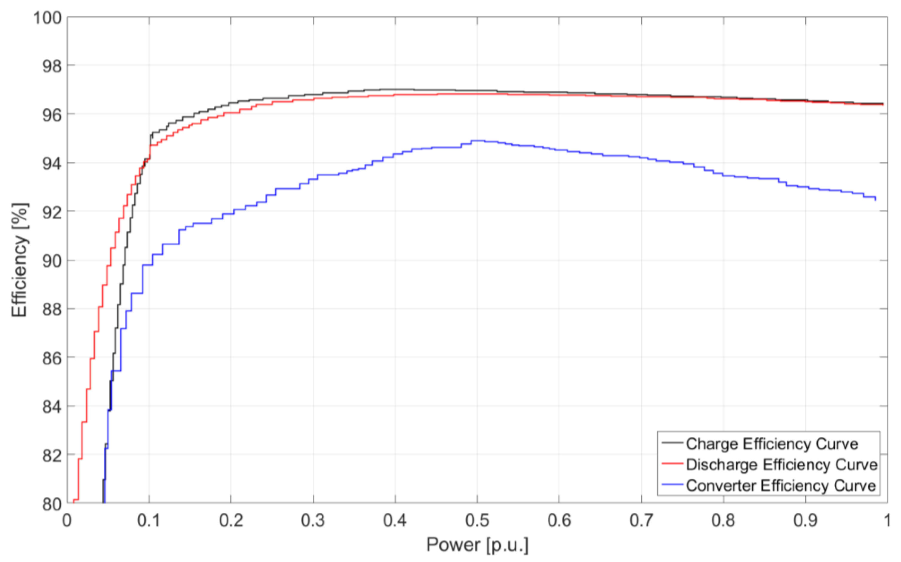
Parameters used in the study are further reported in Table 2, including nominal efficiencies of converters and loss coefficients of connections, depending on different cable lengths. For the sake of simplicity, step-wise approximations of non-linear characteristics for bidirectional DC/DC converter (in charge and discharge) and AC/DC converter efficiency with respect to flowing power, exploited in the iterative solution methodology sketched in Figure 1, are depicted in Figure 4.
Moreover, starting from the data collection of current exploitation of fuel-based service cars within Bari Port Authority, the pattern of EV usage is derived for the specified model. In particular, the traveling intervals and the mobility needs for each journey are estimated through a stochastic procedure from the collected data for each vehicle, depending on seasonality, on the day of the week, and accounting for the possibility of different numbers of journeys during the day. This process leads to the EV usage patterns reported in Figure 5. It can be seen that the service use of EVs is usually concentrated between 10:00 and 19:00. In order to obtain EV power consumption for mobility, an average of 0.12 kWh/km is considered for a 24-kWh size EV battery.
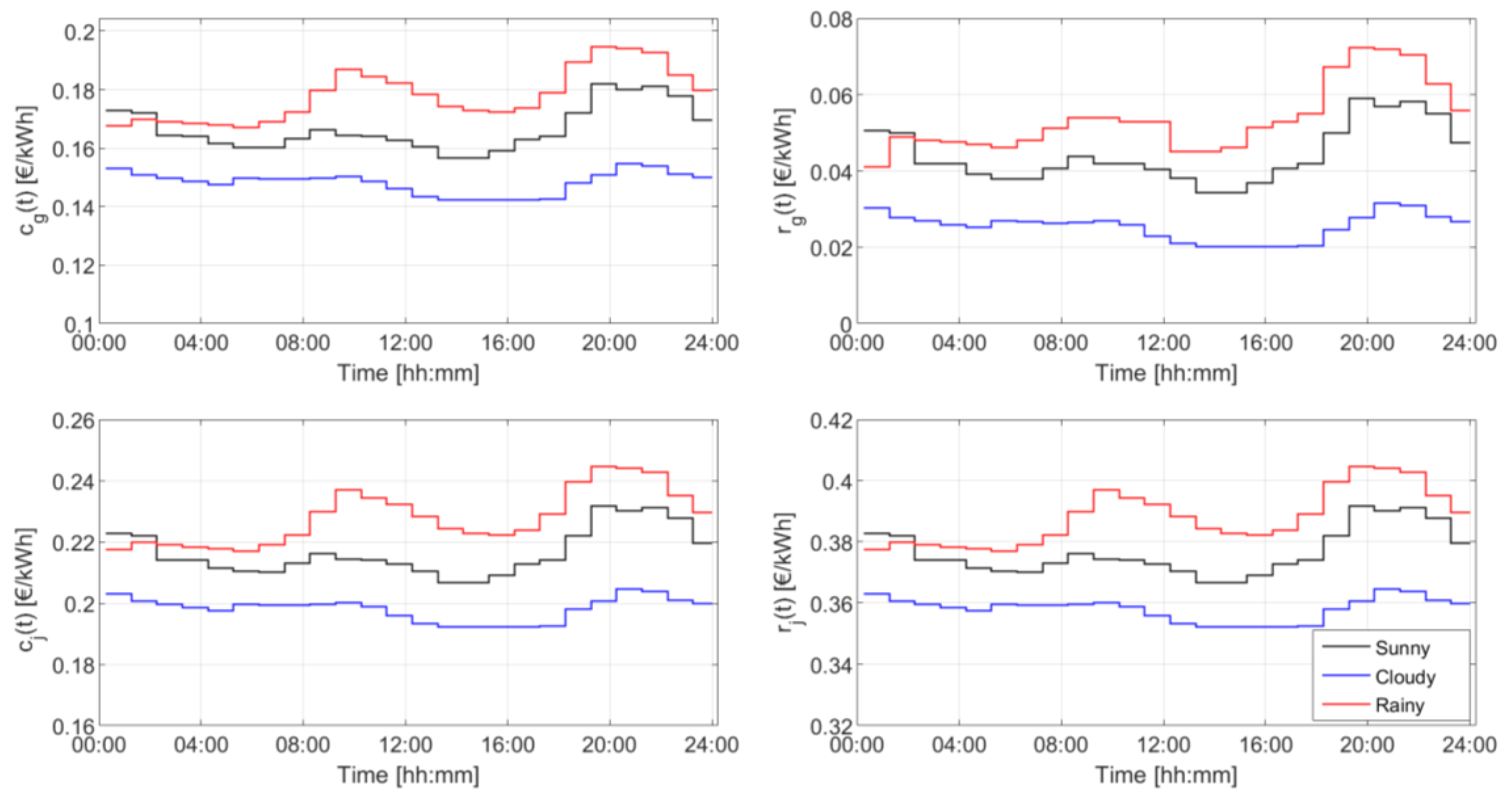
Finally, trends of cost coefficient over the considered days are reported in Figure 6. It can be observed that costs of power purchase from the grid c g ( t ) vary in the range 0.12–0.2 €/kWh. Additionally, r g ( t ) is in the range 0.02–0.08 €/kWh. As for EV utilization, the charge cost c j ( t ) is between 0.18 and 0.25 €/kWh and the premium for discharge r j ( t ) is higher, in the range of 0.32–0.4 €/kWh. In any case, the cost coefficients are higher on rainy days and lower on cloudy days, and they follow analogous trends, with peaks in the morning (10:00–12:00) and evening (19:00–22:00).

4.2. Results, Indicators, and Discussion

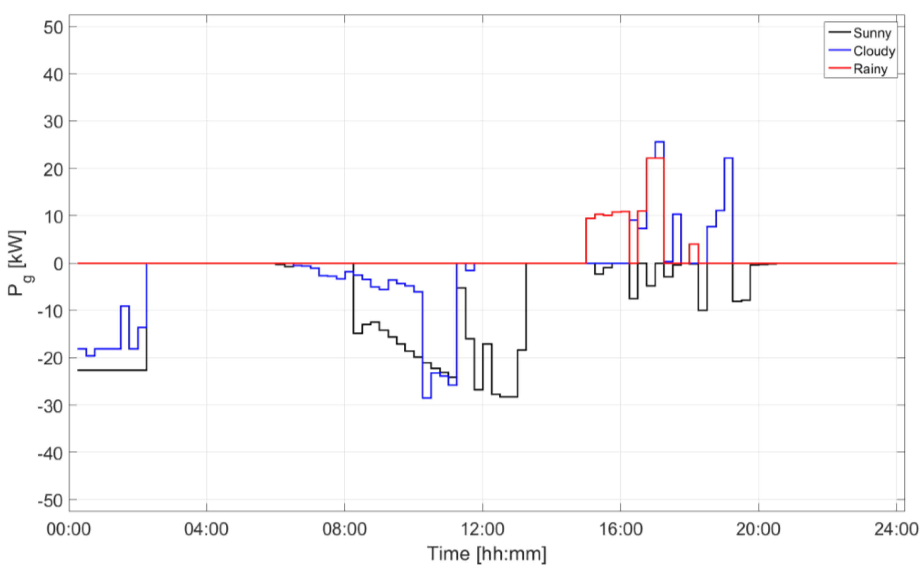
The amount of power exchange at the utility grid interface is shown in Figure 7, before application of loss coefficients. In particular, the represented quantity is P g i n ( t ) P g o u t ( t ) . It is noted that on the sunny day, the DC microgrid exports power between 08:00 and 14:00 due to high PV production, and export is observed also in the intervals 16:00–20:00 and 00:00–02:00, in order to take advantage of the lower price differences, even in the absence of renewable internal production. The behavior on the cloudy day is similar, except for the late afternoon, where power purchase from the utility is observed. On the rainy day, no power delivery is observed, and energy is withdrawn from the grid in the period 15:00–18:00 due to lower internal production. In any case, the power exchange level does not exceed 30 kW, although the maximum level is fixed at 50 kW.
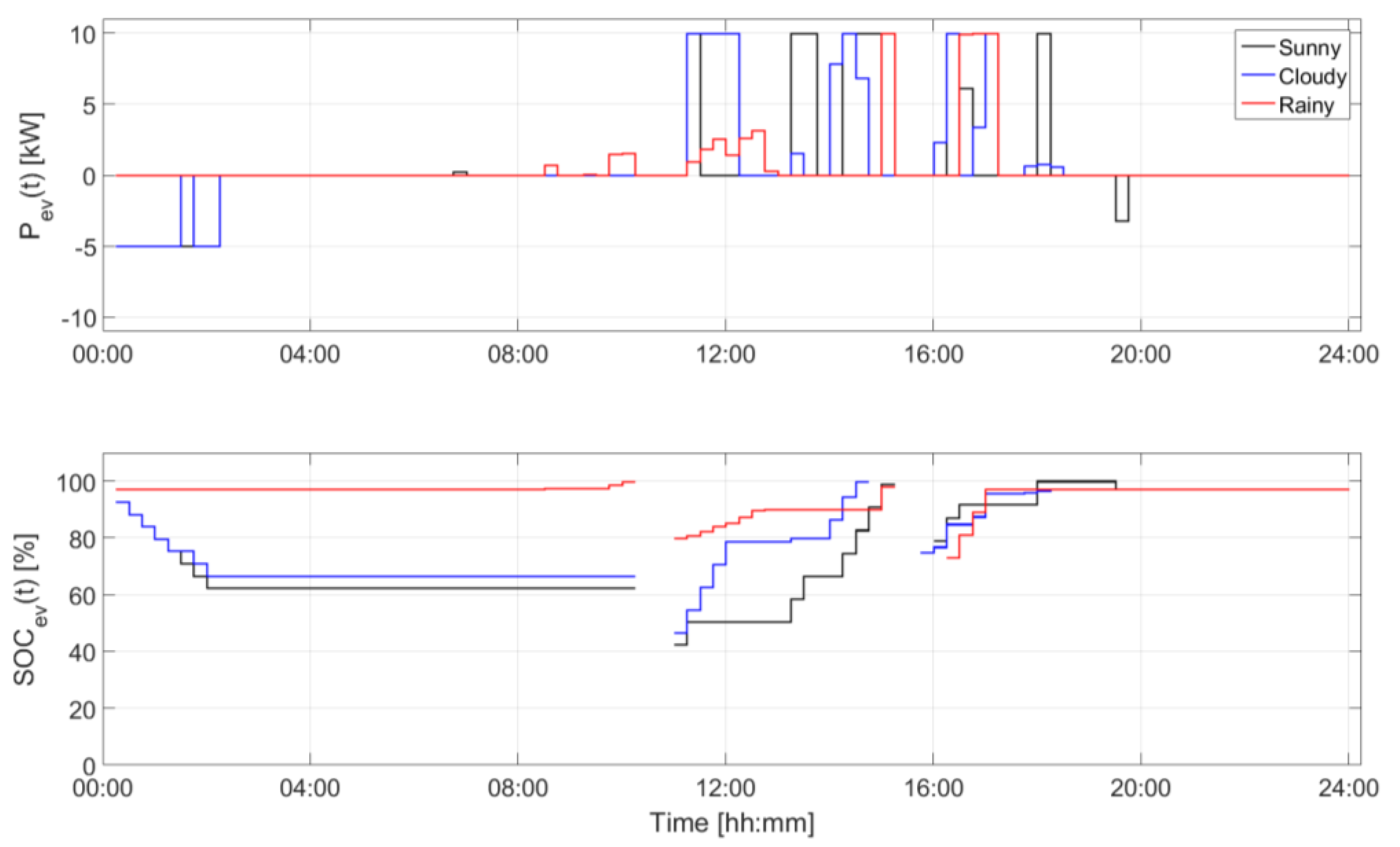
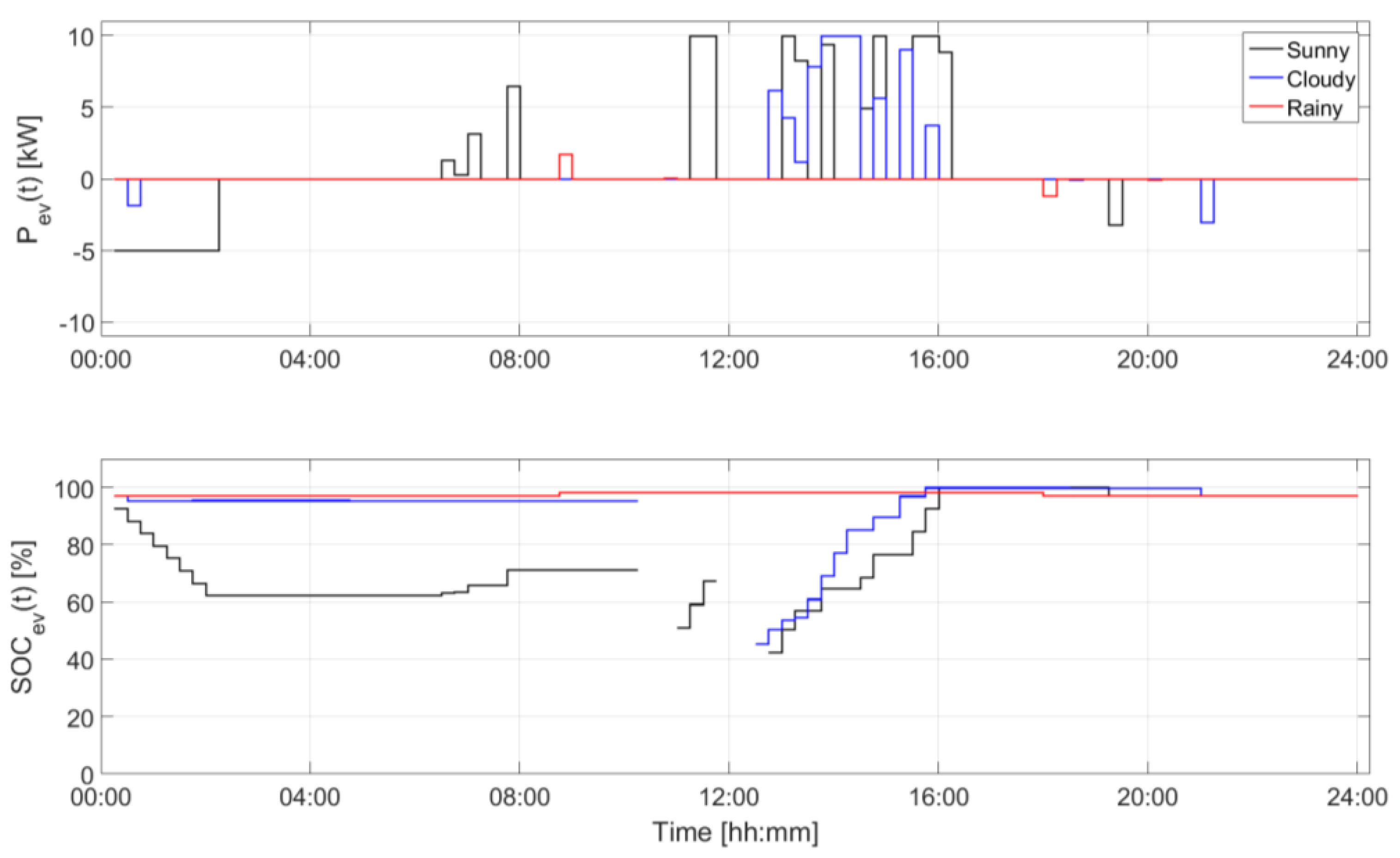
For the sake of comparison, in Figure 8 and Figure 9 the behaviors of EV1 and EV2 are reported for the three considered days in terms of exchanged power before losses, assuming positive values for charge and negative for discharge (i.e., P j c ( t ) P j d ( t ) ), and of state of charge. In the considered conditions, all EVs should attain a SOC of 95% at the end of the day. From the figures it can be noted that the EVs perform early discharge in the first hours of sunny and cloudy days (reaching 5 kW) due to high initial SOC. Therefore, they take advantage of PV availability in short parking intervals to perform intense though not continuous charge. In fact, in the charge stage, they can reach the maximum rate of 10 kW in many intervals, although some alternating behavior is seen in order to efficiently exploit PV production. At the end of the afternoon, SOC is maximum, and a slight discharge is performed. On rainy days, the early discharge is not present and EVs perform only the necessary charge to cover their mobility needs. This is evident for EV2, which is not supposed to be driven on the rainy day, whose battery is kept almost unexploited in order to prevent wearing.
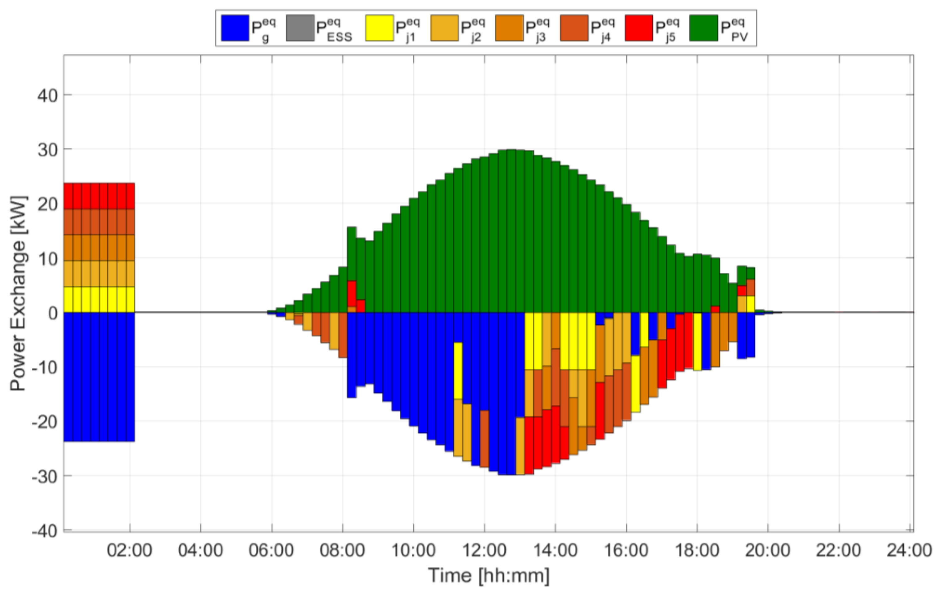
Figure 10 represents the power balance at each time interval for the case of the sunny day. It can be noted that the high PV energy production is mainly delivered to the external grid during the peak price interval (08:00–14:00) and it is used to charge the EVs in the afternoon. During the night, the EVs inject some of their stored energy into the main grid, yielding a revenue. The energy storage system has negligible influence on the algorithm results, because it involves only cost terms (due to the degradation cost of the batteries), and the procedure does not select it, since it is not convenient at current costs. On the cloudy day, as can be derived from Figure 7, the lower PV production causes a lower injection in the main grid, while on the rainy day the PV production is fully used to charge the EVs.
In order to compare the performances of the proposed algorithm with the reference non-linear approach, a set of techno-economic indices is defined and evaluated. In particular, with the aim of analyzing EV behavior, total daily revenue from EV discharge R j d and total daily cost for EV charge C j c are determined using the terms contained in the objective function in Equation (5), as follows:
R j d = t = 1 N t r j ( t ) P j d ( t ) Δ T j ,
C j c = t = 1 N t c j ( t ) P j c ( t ) Δ T j .
Two further indicators are defined. The daily discharge-to-charge ratio γ j indicates the performed EV discharge energy with respect to the total daily charge energy, as described in Equation (34), and is equal to 0 if the EV does not discharge. The average rate of discharge β j relates the EV discharge with the maximum possible rate across the whole day, as reported in Equation (34). Due to the assumption of keeping the same SOC at the beginning and at the end of the day, β j can reach at most 0.5 in the presence of continuous and full discharge, which is the most stressful condition for an EV battery. Finally, the number of cycles performed over the day by each EV, φ j , is drawn.
γ j = t = 1 N t P j d ( t ) Δ T t = 1 N t P j c ( t ) Δ T ,
β j = 1 N t t = 1 N t P j d ( t ) P ¯ j d 100 .
In Table 3, these values are reported for the five EVs and the two algorithms. It can be observed that the contribution of the EVs on the rainy day is lower than in the other two scenarios, since in the absence of excess renewable production, the procedure prefers to limit grid power withdrawal and to use the energy stored in the on-board batteries only for travel, reducing cost and battery wear. In all cases, EV utilization costs exceed relevant revenues, even though on the sunny day this difference is lower. An intense charging/discharging activity is observed on both sunny and cloudy days, where γ j assumes average values between 0.3 and 0.5, with peaks of 0.9 for EV4 when it is not called to travel; however, the average discharge intensity β j is usually below 10% of maximum.
Occasional differences between the proposed procedure and the reference non-linear solution are observed, due to the ability of the stochastic solution process in the GA algorithm to inspect a wider range of the solution space. However, these differences seldom reach 10% on single quantities. It can be noted as well that no EV experiences more than 1 cycle per day. Moreover, the number of cycles in the GA is slightly lower on sunny and cloudy days, thus yielding a less stressful operation of EV batteries than in the MILP case, whereas on rainy days the number is very limited due to lower availability of the PV source.
From a more general point of view, it can be remarked that the proposed indicators give synthetic, immediate, and effective information on EV performances. Therefore, they can be usefully exploited for different subjects (microgrid operator, EV aggregator, and owners) in order to improve the awareness of EVs contributions to energy management tasks, of their exploitation levels, and of relevant economic effects.
In addition to the previous comparison, global microgrid performances are compared by means of overall economic figures, such as total objective function value, as well as total cost C g i n and total revenue R g o u t for energy exchange with the external network, defined as follows:
C g i n = t = 1 N t c g ( t ) P g i n ( t ) Δ T ,
R g o u t = t = 1 N t r g ( t ) P g o u t ( t ) Δ T .
Results are reported in Table 4, where it can be noted that the operation of the microgrid always involves global costs, that are reduced on the sunny day due to energy delivery to the network, whereas cloudy and rainy days show similar global economic efforts, since the wearing cost due to intense EV exploitation counterbalances the reduction of costs for energy purchase. The difference of reported indices between the two procedures is usually below 2% and reaches 9% on the sunny day due to different optimal EV usage values.
As for computational performances, total simulation time and iteration number are reported in Table 5. It can be noted that the reference non-linear problem takes roughly 2 hours to reach the solution, whereas the proposed iterative MILP approach takes less than 1 minute in each case. Therefore, it can be remarked that the proposed MILP iterative procedure allows one to obtain affordable optimal solutions with reduced computational effort and in a reasonable time. Moreover, the number of iterations increases with the worsening of the weather, because only more expensive energy sources are available in this situation. Finally, it can also be noted that the number of generations (in the GA approach) is higher than the iterations in the MILP approach.

5. Conclusions

In this paper, a procedure for optimal operation planning of a DC microgrid for supplying EVs has been proposed. Forecast of PV production and EV mobility needs are used to pursue minimum daily operation cost, including the economic perspective of the microgrid operator and EV owners. For this purpose, a mixed-integer linear programming approach has been exploited, and proper non-linear models of energy storage devices and of DC microgrid peculiarities have been accounted for through an iterative procedure. The proposed approach has been applied to a test DC microgrid, and compared to non-linear formulation. has been solved by means of a genetic algorithm. Different days of operation have been considered, with varying levels of PV production and EV usage, and performances are evaluated in terms of economic results, computational efforts, and EV utilization indices. Simulations have proved that the proposed approach yields comparable solutions with respect to non-linear formulation, with remarkably low computational time. Therefore, the proposed MILP approach has been found to be affordable and fast enough to cope with the time requirements of system operation programming. The approach has also proved to account for DC microgrid peculiarities in an efficient way, demonstrating its applicability in a realistic environment, pointing out limited exploitation of energy storage due to current wear cost. Moreover, the individualization of proper indices for EV exploitation can foster their integration into energy management processes, as well as the application of bidirectional energy exchange through V2G. Future evolutions of the work could include the formulation of several objectives, for instance including load demand peak shaving or the provision of network ancillary services, as well as further security constraints in the procedure in order to efficiently prepare for possible islanding. Moreover, this procedure is aims to be the starting point to develop real-time operation strategies in the presence of variations from day-ahead forecasts.

Author Contributions

M.D., S.B., and G.F. provided the research framework and literature analysis. B.A., L.D.B., and M.T. developed the model. B.A., M.D., and S.B. cared for data collection. B.A., S.B., and G.F. set up the solution procedure. B.A. and L.D.B. performed the simulations. G.F. and M.T. formalized the nomenclature. L.D.B. and G.F. wrote the paper. M.D. and M.T. edited the paper. M.D. and M.T. cared for the funding of the project.

Funding

This document has been created in the context of the CONNECT project. The CONNECT project has received funding from the ECSEL Joint Undertaking under Grant Agreement no. 737434-2 and from the national programs and funding authorities of Germany, Italy, Slovakia, Spain, and The Netherlands. The ECSEL JU has no liability in respect to this document, which merely represents the authors’ views.

Conflicts of Interest

The authors declare no conflict of interest. The funders had no role in the design of the study; in the collection, analyses, or interpretation of data; in the writing of the manuscript, or in the decision to publish the results.

Nomenclature

Indices and auxiliaries
N b Number of storage systems
N e v Number of electric vehicles
N t Number of time steps
i Storage index
j Electric vehicle index
t Time step index
f ( x ) Objective function [€]
Δ T Time step duration [h]
k Iteration index
k m a x Maximum number of iterations
ε Solution convergence threshold
Input parameters
r g ( t ) Unitary revenue for the energy injected into the utility grid at time step t [€/kWh]
r j ( t ) Unitary revenue for the discharge energy of the j-th EV at time step t [€/kWh]
c g ( t ) Unitary cost for the energy withdrawal from the grid at time step t [€/kWh]
c j ( t ) Unitary cost for the charge energy of the j-th EV at time step t [€/kWh]
w i ( t ) Degradation cost of the i-th storage [€/kWh]
w j ( t ) Degradation cost of the j-th EV [€/kWh]
P ¯ g Maximum power exchange with utility grid [kW]
P ¯ i c ,    P ¯ i d Maximum charge/discharge power for the i-th storage [kW]
P ¯ j c , P ¯ j d Maximum charge/discharge power for the j-th EV [kW]
S ¯ i , S _ i Max/min SOC of the i-th storage [kWh]
S ¯ j , S _ j Max/min SOC of the j-th EV [kWh]
P P V ( t ) Photovoltaic production power at time step t [kW]
η i c ( t ) , η i d ( t ) Charge/discharge efficiency of the i-th storage at time step t
η j c ( t ) , η j d ( t ) Charge/discharge efficiency of the j-th EV at time step t
ρ i Self-discharge of the i-th storage [kW]
S i i n i Initial SOC of the i-th storage [kWh]
ρ j Self-discharge of the j-th EV [kW]
S j i n i Initial SOC of the j-th EV [kWh]
Δ S j ( t ) SOC reduction of the j-th EV for mobility needs in the time step t [kWh]
State variables
P g i n ( t ) Power withdrawn from AC grid at time step t [kW]
P g o u t ( t ) Power injected into the AC grid at time step t [kW]
P i c ( t ) Charge power of the i-th storage at time step t [kW]
P i d ( t ) Discharge power of the i-th storage at time step t [kW]
P j c ( t ) Charge power of the j-th EV at time step t [kW]
P j d ( t ) Discharge power of the j-th EV at time step t [kW]
S i ( t ) SOC of the i-th storage at time step t [kWh]
S j ( t ) SOC of the j-th EV at time step t [kWh]
v g ( t ) Binary variable of the grid power exchange state (1 if the microgrid is draining power from the external grid, 0 if the microgrid is injecting power)
v i ( t ) Binary variable of the i-th storage charging state (1 charging, 0 discharging)
v j ( t ) Binary variable of the j-th EV charging state (1 charging, 0 discharging)

References

  1. Urbanelli, A.; Sallati, A.; Ciasca, F.; Aluisio, B.; Vergine, C.; Zeni, L.; Petrucci, M.; Forte, G.; Trovato, M. Electric vehicle grid impacts—Opportunities and evaluation on the Italian Transmission Grid. In Proceedings of the 2018 AEIT International Annual Conference, Bari, Italy, 3–5 October 2018; pp. 1–6. [Google Scholar] [CrossRef]
  2. International standard IEC 62196-1. Plugs, Socket-Outlets, Vehicle Connectors and Vehicle Inlets—Conductive Charging of Electric Vehicles—Part 1: General Requirements, 3rd ed.; International Electrotechnical Commission: Geneva, Switzerland, 2014. [Google Scholar]
  3. Abousleiman, R.; Scholer, R. Smart Charging: System design and implementation for interaction between plug-in electric vehicles and the power grid. IEEE Trans. Transp. Electrif. 2015, 1, 18–25. [Google Scholar] [CrossRef]
  4. Moghaddam, Z.; Ahmad, I.; Habibi, D.; Phung, Q.V. Smart Charging Strategy for Electric Vehicle Charging Stations. IEEE Trans. Transp. Electrif. 2018, 4, 76–88. [Google Scholar] [CrossRef]
  5. González Vayá, M.; Andersson, G. Optimal bidding strategy of a plug-in electric vehicle aggregator in day-ahead electricity markets under uncertainty. IEEE Trans. Power Syst. 2015, 30, 2375–2385. [Google Scholar] [CrossRef]
  6. Bhatti, A.R.; Salam, Z.; Aziz, M.J.B.A.; Yee, K.P.; Ashique, R.H. Electric vehicles charging using photovoltaic: Status and technological review. Renew. Sust. Energy Rev. 2016, 54, 34–47. [Google Scholar] [CrossRef]
  7. Sbordone, D.; Bertini, I.; Di Pietra, B.; Falvo, M.C.; Genovese, A.; Martirano, L. EV fast charging stations and energy storage technologies: A real implementation in the smart micro grid paradigm. Electr. Power Syst. Res. 2015, 120, 96–108. [Google Scholar] [CrossRef]
  8. Ashique, R.H.; Salam, Z.; Bin Abdul Aziz, M.J.; Bhatti, A.R. Integrated photovoltaic-grid dc fast charging system for electric vehicle: A review of the architecture and control. Renew. Sust. Energy Rev. 2017, 69, 1243–1257. [Google Scholar] [CrossRef]
  9. Kaur, S.; Kaur, T.; Khanna, R.; Singh, P. A State of the art of DC microgrids for Electric Vehicle Charging. In Proceedings of the 4th IEEE ISPC 2k17 Conference, Solan, India, 21–23 September 2017; pp. 381–386. [Google Scholar] [CrossRef]
  10. Aboli, R.; Ramezani, M.; Falaghi, H. Joint optimization of day-ahaed and uncertain near real-time operation of microgrids. Electr. Power Syst. Res. 2019, 107, 34–46. [Google Scholar] [CrossRef]
  11. Wu, D.; Zeng, H.; Lu, C.; Boulet, B. Two-Stage Energy Management for Office Buildings With Workplace EV Charging and Renewable Energy. IEEE Trans. Transp. Electrif. 2017, 3, 225–237. [Google Scholar] [CrossRef]
  12. Kamankesh, H.; Agelidis, V.G.; Kavousi-Fard, A. Optimal scheduling of renewable micro-grids considering plug-in hybrid electric vehicle charging demand. Energy 2016, 100, 285–297. [Google Scholar] [CrossRef]
  13. Diaz-Cachinero, P.; Munoz-Hernandez, J.I.; Contreras, J. A Linear Model for Operating Microgrids with Renewable Resources, Battery Degradation Costs and Electric Vehicles. In Proceedings of the 2018 EEM International Conference, Lodz, Poland, 27–29 June 2018; pp. 1–5. [Google Scholar] [CrossRef]
  14. Zhao, T.; Xiao, J.; Koh, L.H.; Wang, P.; Ding, Z. Strategic Day-ahead Bidding for Energy Hubs with Electric Vehicles. In Proceedings of the 2018 IEEE EI2 Conference, Beijing, China, 20–22 October 2018; pp. 1–6. [Google Scholar] [CrossRef]
  15. Bahramara, S.; Golpira, H. Robust optimization of micro-grids operation problem in the presence of electric vehicles. Sustain. Cities Soc. 2018, 37, 388–395. [Google Scholar] [CrossRef]
  16. Lu, X.; Zhou, K.; Yang, S.; Liu, H. Multi-objective optimal load dispatch of microgrid with stochastic access of electric vehicles. J. Cleaner Prod. 2018, 195, 187–199. [Google Scholar] [CrossRef]
  17. Kuran, M.S.; Carneiro Viana, A.; Iannone, L.; Kofman, D.; Mermoud, G.; Vasseur, J.P. A Smart Parking Lot Management System for Scheduling the Recharging of Electric Vehicles. IEEE Trans. Smart Grid 2015, 6, 2942–2953. [Google Scholar] [CrossRef]
  18. Li, W.; Zhang, T.; Wang, R. Energy management model of charging station micro-grid considering random arrival of electric vehicles. In Proceedings of the 2018 IEEE International Conference on Energy Internet, Beijing, China, 21–25 May 2018; pp. 1–6. [Google Scholar] [CrossRef]
  19. Tabari, M.; Yazdani, A. An Energy Management Strategy for a DC Distribution System for Power System Integration of Plug-In Electric Vehicles. IEEE Trans. Smart Grid 2016, 7, 659–668. [Google Scholar] [CrossRef]
  20. Van der Kam, M.; Van Sark, W. Smart charging of electric vehicles with photovoltaic power and vehicle-to-grid technology in a microgrid; a case study. Appl. Energy 2015, 152, 20–30. [Google Scholar] [CrossRef] [Green Version]
  21. Zhang, Y.; Teng, Y.; Zhang, Z.; Li, J.; Jiang, R.; Huang, Q. Scheduling Optimization of Microgrid Considering Electric Vehicles. In Proceedings of the 2017 IEEE International Conference on Power and Renewable Energy, Chengdu, China, 20–23 September 2017; pp. 742–746. [Google Scholar] [CrossRef]
  22. Aliasghari, P.; Mohammadi-Ivatloo, B.; Alipour, M.; Abapour, M.; Zare, K. Optimal scheduling of plug-in electric vehicles and renewable microgrid in energy and reserve markets considering demand response program. J. Cleaner Prod. 2018, 186, 293–303. [Google Scholar] [CrossRef]
  23. Honarmand, M.; Zakariazadeh, A.; Jadid, S. Integrated scheduling of renewable generation and electric vehicles parking lot in a smart microgrid. Energy Convers. Manage. 2014, 86, 745–755. [Google Scholar] [CrossRef]
  24. Tabatabaee, S.; Mortazavi, S.S.; Niknam, T. Stochastic scheduling of local distribution systems considering high penetration of plug-in electric vehicles and renewable energy sources. Energy 2017, 121, 480–490. [Google Scholar] [CrossRef]
  25. Aluisio, B.; Conserva, A.; Dicorato, M.; Forte, G.; Trovato, M. Optimal operation planning of V2G-equipped Microgrid in the presence of EV aggregator. Electr. Power Syst. Res. 2017, 152, 295–305. [Google Scholar] [CrossRef]
  26. Mortaz, E.; Valenzuela, J. Microgrid energy scheduling using storage from electric vehicles. Electr. Power Syst. Res. 2017, 143, 554–562. [Google Scholar] [CrossRef]
  27. Chen, C.; Duan, S. Optimal Integration of Plug-In Hybrid Electric Vehicles in Microgrids. IEEE Trans. Ind. Inform. 2014, 10, 1917–1926. [Google Scholar] [CrossRef]
  28. Kumar Nunna, H.S.V.S.; Battula, S.; Doolla, S.; Srinivasan, D. Energy Management in Smart Distribution Systems With Vehicle-to-Grid Integrated Microgrids. IEEE Trans. Smart Grid 2018, 9, 4004–4016. [Google Scholar] [CrossRef]
  29. Nong, J.; Zhang, Y.; Wang, N.; Xu, W. Coordinated Dispatch Strategy of Virtual Power Plant Considering Electric Vehicle and Battery Management. In Proceedings of the 2018 37th CCC Conference, Wuhan, China, 25–27 July 2018; pp. 8798–8802. [Google Scholar] [CrossRef]
  30. Lakshminarayanan, V.; Pramanick, S.; Rajashekara, K.; Ben-Brahim, L.; Gastli, A. Optimal energy management scheme for electric vehicle integration in microgrid. In Proceedings of the 2017 IEEE NAPS Conference, Morgantown, WV, USA, 17–19 September 2017; pp. 1–6. [Google Scholar] [CrossRef]
  31. Tushar, W.; Yuen, C.; Huang, S.; Smith, D.B.; Poor, H.V. Cost Minimization of Charging Stations With Photovoltaics: An Approach With EV Classification. IEEE Trans. Intell. Transp. Syst. 2016, 17, 156–169. [Google Scholar] [CrossRef]
  32. Lu, X.; Liu, N.; Chen, Q.; Zhang, J. Multi-objective Optimal Scheduling of a DC Micro-grid Consisted of PV System and EV Charging Station. In Proceedings of the 2014 IEEE ISGT Asia Conference, Kuala Lumpur, Malaysia, 20–23 May 2014; pp. 487–491. [Google Scholar] [CrossRef]
  33. Yao, L.; Damiran, Z.; Lim, W.H. Optimal Charging and Discharging Scheduling for Electric Vehicles in a Parking Station with Photovoltaic System and Energy Storage System. Energies 2017, 10, 550. [Google Scholar] [CrossRef]
  34. Yan, Q.; Zhang, B.; Kezunovic, M. Optimized Operational Cost Reduction for an EV Charging Station Integrated With Battery Energy Storage and PV Generation. IEEE Trans. Smart Grid 2019, 10, 2096–2106. [Google Scholar] [CrossRef]
  35. Liao, Y.-T.; Lu, C.N. Dispatch of EV Charging Station Energy Resources for Sustainable Mobility. IEEE Trans. Transp. Electrif. 2015, 1, 86–93. [Google Scholar] [CrossRef]
  36. Guo, Y.; Xiong, J.; Xu, A.; Su, W. Two-Stage Economic Operation of Microgrid-Like Electric Vehicle Parking Deck. IEEE Trans. Smart Grid 2016, 7, 1703–1713. [Google Scholar] [CrossRef]
  37. Lotfi, H.; Khodaei, A. AC versus DC Microgrid Planning. IEEE Trans. Smart Grid 2017, 8, 296–304. [Google Scholar] [CrossRef]
  38. Shah, T.; Ansari, Z.A. An Overview of Intelligent Energy Management System for DC Microgrid: System and Communication Architecture and Application in Power Distribution System. In Proceedings of the 2018 IEEE 13th International Conference on Industrial and Information Systems (ICIIS), Rupnagar, India, 1–2 December 2018. [Google Scholar] [CrossRef]
  39. Shuai, Z.; Fang, J.; Ning, F.; Shen, Z.J. Hierarchical structure and bus voltage control of DC microgrid. Renew. Sustain. Energy Rev. 2018, 82, 3670–3682. [Google Scholar] [CrossRef]
  40. Sechilariu, M.; Locment, F.; Trigueiro Dos Santos, L. A Conceptual Framework for Full Optimal Operation of a Grid-Connected DC Microgrid. In Proceedings of the 2018 IEEE International Conference on Industrial Electronics for Sustainable Energy Systems (IESES), Hamilton, New Zealand, 31 January–2 February 2018; pp. 296–301. [Google Scholar] [CrossRef]
  41. Zia, M.F.; Elbouchikhi, E.; Benbouzid, M. Optimal operational planning of scalable DC microgrid with demand response, islanding, and battery degradation cost considerations. Appl. Energy 2019, 237, 695–707. [Google Scholar] [CrossRef]
  42. Gil-Gonzalez, W.; Montoya, O.D.; Holguin, E.; Garces, A.; Grisales-Noreña, L.F. Economic dispatch of energy storage systems in dc microgrids employing a semidefinite programming model. J. Energy Storage 2019, 21, 1–8. [Google Scholar] [CrossRef]
  43. Tavakoli, M.; Shokridehaki, F.; Akorede, M.R.; Marzband, M.; Vechiu, I.; Pouresmaeil, E. CVaR-based energy management scheme for optimal resilience and operational cost in commercial building microgrids. Electr. Power Energy Syst. 2018, 100, 1–9. [Google Scholar] [CrossRef]
  44. Al-Sakkaf, S.; Kassas, M.; Khalid, M.; Abido, M.A. An Energy Management System for Residential Autonomous DC Microgrid Using Optimized Fuzzy Logic Controller Considering Economic Dispatch. Energies 2019, 12, 1457. [Google Scholar] [CrossRef]
  45. Iovine, A.; Rigaut, T.; Damm, G.; De Santis, E.; Di Benedetto, M.D. Power management for a DC MicroGrid integrating renewables and storages. Control Eng. Pract. 2019, 85, 59–79. [Google Scholar] [CrossRef]
  46. Deshmukh, R.R.; Ballal, M.; Suryawanshi, H.M.; Mishra, M.K. An Adaptive Approach for Effective Power Management in DC Microgrid Based on Virtual Generation in Distributed Energy Sources. IEEE Trans. Industr. Inform. 2019, 1. [Google Scholar] [CrossRef]
  47. Nougain, V.; Panigrahi, B.K. Real Time Energy Management System and Control Strategy for DC Microgrid. In Proceedings of the 2018 8th IEEE India International Conference on Power Electronics (IICPE), Jaipur, India, 13–15 December 2018. [Google Scholar] [CrossRef]
  48. Aluisio, B.; Dicorato, M.; Ferrini, I.; Forte, G.; Sbrizzai, R.; Trovato, M. Optimal sizing procedure for Electric Vehicle Supply Infrastructure based on DC microgrid with station commitment. Energies 2019, 12, 1901. [Google Scholar] [CrossRef]
  49. Ortega-Vazquez, M.A. Optimal scheduling of electric vehicle charging and vehicle-to-grid services at household level including battery degradation and price uncertainty. IET Gener. Transm. Distrib. 2014, 8, 1007–1016. [Google Scholar] [CrossRef]
  50. Landi, M.; Gross, G. Measurement techniques for online battery state of health estimation in vehicle-to-grid applications. IEEE Trans. Instrum. Meas. 2014, 63, 1224–1234. [Google Scholar] [CrossRef]
  51. Aluisio, B.; Dicorato, M.; Forte, G.; Trovato, M. A Monte-Carlo Based procedure for optimal sizing of integrated Electric Vehicle Supply Infrastructure. In Proceedings of the IEEE ISGT Europe 2017 Conference, Turin, Italy, 26–29 September 2017; pp. 1–6. [Google Scholar] [CrossRef]
  52. Aluisio, B.; Dicorato, M.; Ferrini, I.; Forte, G.; Trovato, M. AC and DC solutions for Electric Vehicle microgrid: Sizing and reliability analysis. In Proceedings of the IEEE 2018 EEEIC/I&CPS Europe International Conference, Palermo, Italy, 12–15 June 2018; pp. 1–6. [Google Scholar] [CrossRef]
  53. Nemhauser, G.L.; Wolsey, L.A. Integer and Combinatorial Optimization; John Wiley & Sons Inc.: Hoboken, NJ, USA, 1999. [Google Scholar]
  54. Fortin, M.; Glowniski, R. Augmented Lagrangian Methods: Applications to the Numerical Solution of Boundary-Value Problems, 1st ed.; North-Holland: Amsterdam, The Netherlands, 2000. [Google Scholar]
  55. Available online: www.wunderground.com, weather stations network (accessed on 31 January 2018).
  56. Duffie, J.A.; Beckman, W.A. Solar Engineering of Thermal Processes, 4th ed.; John Wiley & Sons, Inc.: Hoboken, NJ, USA, 2013. [Google Scholar]
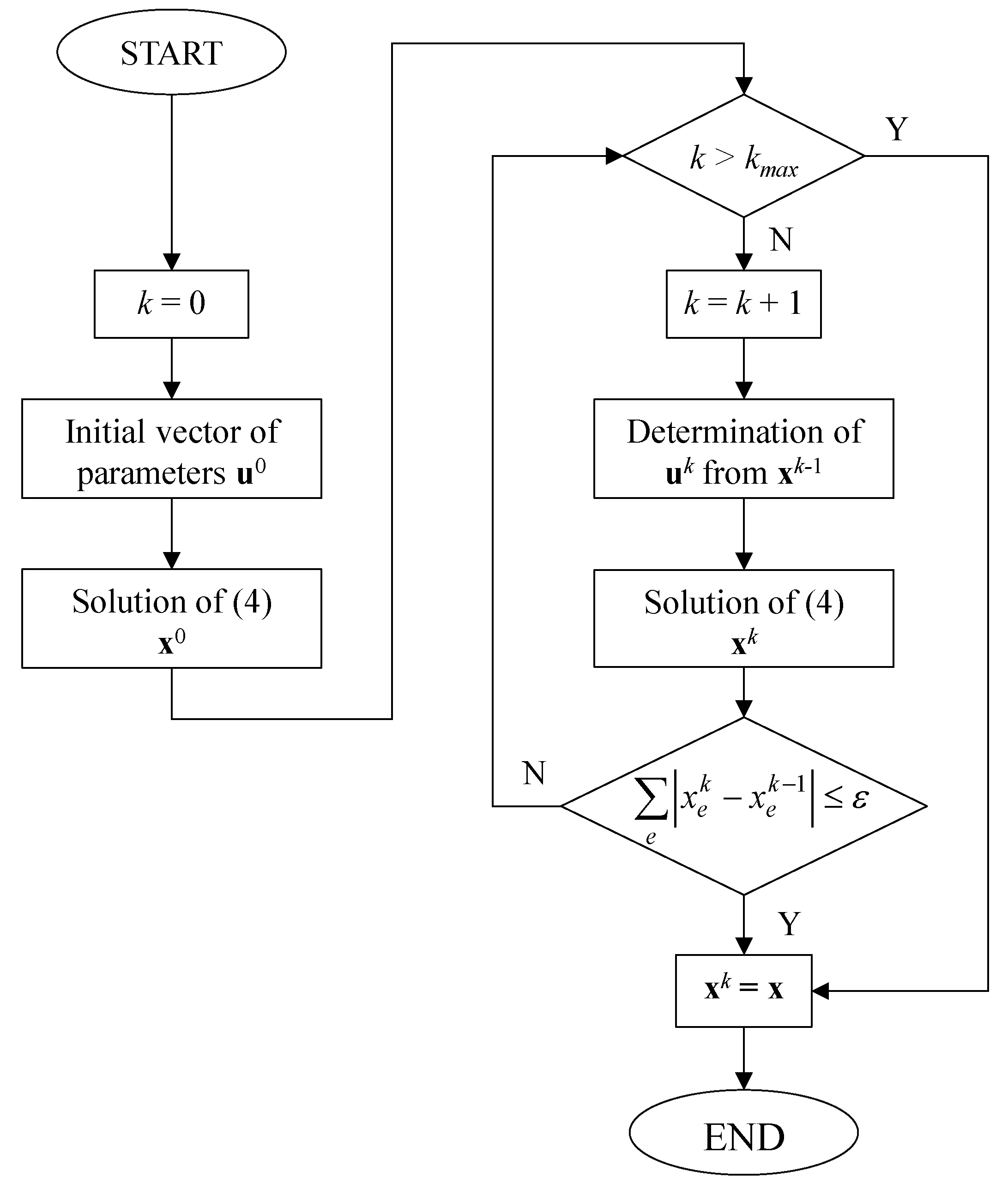
Figure 1. Flowchart of the iterative methodology to account for non-linear parameters in the mixed integer linear programming (MILP) algorithm.
Applsci 09 02687 g001
Figure 2. Grid scheme of the test direct-current (DC) microgrid.
Applsci 09 02687 g002
Figure 3. Forecasted output of the photovoltaic system for the three different days.
Applsci 09 02687 g003
Figure 4. Converter efficiency curves.
Applsci 09 02687 g004
Figure 5. Forecasted EV exploitation patterns on the three different days.
Applsci 09 02687 g005
Figure 6. Unitary cost trends on the three different days.
Applsci 09 02687 g006
Figure 7. Power exchanged with the utility grid in the three days.
Applsci 09 02687 g007
Figure 8. Power exchange between the test microgrid and EV 1 and the related SOC on the three days.
Applsci 09 02687 g008
Figure 9. Power exchange between the test microgrid and EV 2 and the related SOC on the three days.
Applsci 09 02687 g009
Figure 10. Microgrid power balance on the sunny day.
Applsci 09 02687 g010
Table 1. Test system. Sizes of installed devices.
DeviceInstalled Size (kW)Installed Size (kWh)State of Charge Max/Min (p.u.)Converter Size (kW)
Photovoltaic (PV)40------40
Energy storage system (ESS)30600.95/0.2530
Charging station (CS) ---------10
Utility grid---------50
Electric vehicle (EV)---241.0/0.2---
Table 2. Test system. Nominal Parameters.
ParameterSymbolNominal Value
EV charge efficiency η j c 0.95
EV discharge efficiency η j d 0.95
Grid converter efficiency h g 0.93
DC/DC converter efficiency h i ,    h j ,    h P V 0.965
Storage charge efficiency η i c 0.9
Storage discharge efficiency η i d 0.9
Connection losses coefficient α 0.035÷0.055
Table 3. Techno-economic performances of EVs for the three typical days.
Proposed Iterative MILPReference Non-Linear with GA
EV 1EV 2EV 3EV 4EV 5EV 1EV 2EV 3EV 4EV 5
R j d
[€]
Sunny4.144.143.934.144.854.154.153.844.24.48
Cloudy3.170.453.623.453.173.190.53.273.463.17
Rainy00.13000.300.150.060.020.31
C j c
[€]
Sunny5.045.3854.744.835.25.525.074.854.74
Cloudy4.563.274.542.014.584.663.364.432.074.69
Rainy3.190.11.783.520.223.30.111.823.550.22
γ j
[p.u.]
Sunny0.450.420.440.480.550.440.410.420.470.52
Cloudy0.370.070.430.920.370.370.080.40.90.36
Rainy00.74000.8200.770.0200.83
β j
[%]
Sunny998.57910.579.039.038.359.139.76
Cloudy7.291.038.337.957.297.331.167.537.957.3
Rainy00.28000.6400.320.140.040.65
φ j Sunny0.640.640.600.640.760.640.640.590.650.70
Cloudy0.500.080.580.550.500.500.090.520.550.50
Rainy0.000.020.000.000.050.000.030.010.050.05
Table 4. Techno-economic performances of the microgrid for the three typical days.
Proposed Iterative MILPReference Non-Linear with GA
R g o u t
[€]
Sunny6.776.66
Cloudy1.951.92
Rainy0.000.00
C g i n
[€]
Sunny0.000.00
Cloudy4.204.28
Rainy4.824.90
f ( x )
[€]
Sunny8.669.53
Cloudy16.4017.06
Rainy15.8816.08
Table 5. Computational performances of solution algorithms for the three typical days.
Proposed Iterative MILPReference Non-Linear with GA
Simulation time [s]Sunny26.067216.76
Cloudy28.947222.93
Rainy44.117217.23
Iteration number
or Generation number
Sunny412
Cloudy513
Rainy1016