Article

Predictive Speed-Control Algorithm Based on a Novel Extended-State Observer for PMSM Drives

1
College of Automation, Qingdao University, Qingdao 266071, China
2
School of Control Science and Engineering, Shandong University, Jinan 250061, China
*
Author to whom correspondence should be addressed.
Appl. Sci. 2019, 9(12), 2575; https://doi.org/10.3390/app9122575
Submission received: 28 April 2019 / Revised: 8 June 2019 / Accepted: 21 June 2019 / Published: 25 June 2019
(This article belongs to the Section Electrical, Electronics and Communications Engineering)

Abstract

:
To enhance the control performance of permanent-magnet synchronous motor (PMSM) drive systems, achieving high-precision motion control, a generalized predictive control (GPC) method based on a novel extended-state observer (ESO) is investigated for the speed control of PMSM. In this paper, the controller design consists of two steps. Firstly, according to the continuous time model of PMSM, using the Taylor series expansion, the predictive value of motor speed in finite time is derived, and the single-loop speed controller by combining the speed loop and q - axis current loop is obtained through the defined cost function. The structure of the controller is simple compared to other forms. Secondly, considering the uncertainty of the load torque and the model uncertainties, a novel extended-state observer is designed to compute the actual torque, and the observed value is introduced to the GPC controller. The simulation and experimental results show that the proposed GPC+ESO control method has superior dynamic performance and strong robustness.

1. Introduction

Permanent-magnet synchronous motors (PMSMs) are extensively used in the field of electric vehicle (EV) drive systems, robots, and CNC machine tools, because of its advantages in compact structure, reliability, high efficiency, and power density. The traditional proportional integral (PI) controller with cascade control structure is most commonly used for speed control of PMSMs. PI control method is simple and reliable, and the controller can be turned without knowledge of the mathematical model. However, in above applications, excellent dynamic response and high-precision tracking performance are the most important requirements. Simultaneously, due to the existence of inevitable model uncertainties and external disturbances, the general linear control methods cannot satisfy the requirement in high-performance applications of PMSM control systems. To improve the performance of the control system, many advanced nonlinear control methods have been developed in recent years, such as linearization control [1], adaptive control [2,3], sliding mode control [4,5], fuzzy control [6], and neural network control [7,8]. These control methods can improve the performance of the motor in different aspects.
Recently, as a practical and advanced industrial control technology, model predictive control (MPC) has attracted wide attention. MPC requires the explicit use of a dynamic model to predict process outputs of the future, then the future control action is obtained according to optimization of a target function or a cost function at each sampling time [9]. The application of MPC in PMSM has been mentioned in [10,11]. In [10], according to the linear discrete time model of PMSM, a predictive control method is used in the speed and current loop, and a disturbance model is embedded in the speed loop to improve the robustness of the motor. In [11], a novel predictive controller is proposed which combines the speed and current loop together, and through optimizing a cost function consisting of a future speed tracking and d - q axis current error, the future control action can be derived. They are all studies based on the discrete time model of system, and the control strategies based on online optimization suffer from a heavy computational burden. In addition to above predictive methods, a generalized predictive control method for nonlinear system based on the continue time model is reported [12,13] and used in PMSM control systems [14,15]. Because there is no need for online optimization, the amount of calculation is decreased. In [14], a nonlinear predictive controller for PMSM is designed, and the load torque as a disturbance variable is estimated by an observer. In [15], the predictive control is applied in the speed and current loop, respectively, then a disturbance observer is designed to estimate the parametric uncertainties and the load torque value. According to the above literature, the MPC method is applied to the controller design and enhances the control performance of PMSM drive systems.
Although the mentioned predictive control methods above have many advantages in motor control, MPC is still a model-based control method, and it does not work for the parameter variations and external load disturbance. To achieve an accurate control of the motor, the disturbances should be accurately estimated and compensated. There are many observers for disturbances estimation, such as unknown input observer [16], disturbance observer [17,18], extended-state observer [19,20,21]. The applications of the observer for PMSM drive systems are presented in [18,19]. In [18], the sliding mode disturbance observer is used to restrain external disturbance which can improve the anti-disturbance capability of the PMSM drive systems. In [19], an extended-state observer is applied to the speed controller of PMSM to estimate disturbance.
In this paper, according to the continue time predictive control theory, a novel predictive speed controller based on the extended-state observer is proposed for PMSM, which combines the speed loop and the q - axis current loop together. The predictive controller has only one adjusted parameter, and it simplifies the design of the controller. Meanwhile, a novel extended-state observer is designed to observe the load disturbance, which is used for the predictive controller. Finally, the effectiveness of the proposed approach is verified by simulation and experiment in LINKS-RT platform, and the results prove that the novel controller can achieve good speed tracking and strong robustness for the disturbance in different conditions.
This paper is organized as follows. Section 2 provides a mathematical model of PMSM. Section 3 introduces the design of generalized predictive controller. A novel extended-state observer is proposed to estimate the load disturbance in Section 4. Section 5 shows the simulation and experimental results. The conclusion is presented in Section 6.

2. The Mathematical Model of PMSM

The mathematical model of the PMSM in the d - q axis rotor reference frame can be expressed as
L d d i d d t = R s i d + n p ω L q i q + u d L q d i q d t = R s i q n p ω L d i d n p ω Φ + u q J d ω d t = n p L d L q i d i q + Φ i q τ L B ω
where L d , L q are d - axis and q - axis stator inductance, i d , i q , u d , u q are the stator current and voltage in d - q axis reference frame. R s is the stator resistance of the motor. n p is the number of pole pairs. ω is the mechanical angular speed of the motor. Φ is the rotor flux. J is the moment of inertia. τ L is the load torque. B is friction coefficient.
The control objection is to design a speed controller for PMSM, which combines the speed loop and q - axis current loop together, and the controller can realize the speed tracking. For this purpose, define the state variable, input variable and output variable as x = i q ω T , u = u q , y = ω , respectively. Then the last two formula of Equation (1) can be described as
x ˙ = f ( x ) + g 1 x u y = ω = g 2 x x
where g 1 ( x ) = 1 L q 0 T , g 2 ( x ) = 0 1 , f ( x ) = R s i q L q n p ω L d i d L q n p ω Φ L q n p L d L q i d i q + Φ i q J τ L J B ω J
The control system diagram of PMSM is shown in Figure 1. The overall control system includes predictive speed controller, extended-state observer for the disturbance, PI controller for the d - axis current control, inverter, space vector pulse width modulation (SVPWM) and PMSM. As seen from Figure 1, i d = 0 control is used in this paper, and the PI controller is adapted in d - axis current loop and the predictive controller is adapted for the speed control. The whole speed-control algorithm is proposed to realize accurate speed tracking and strong robustness for the disturbances.

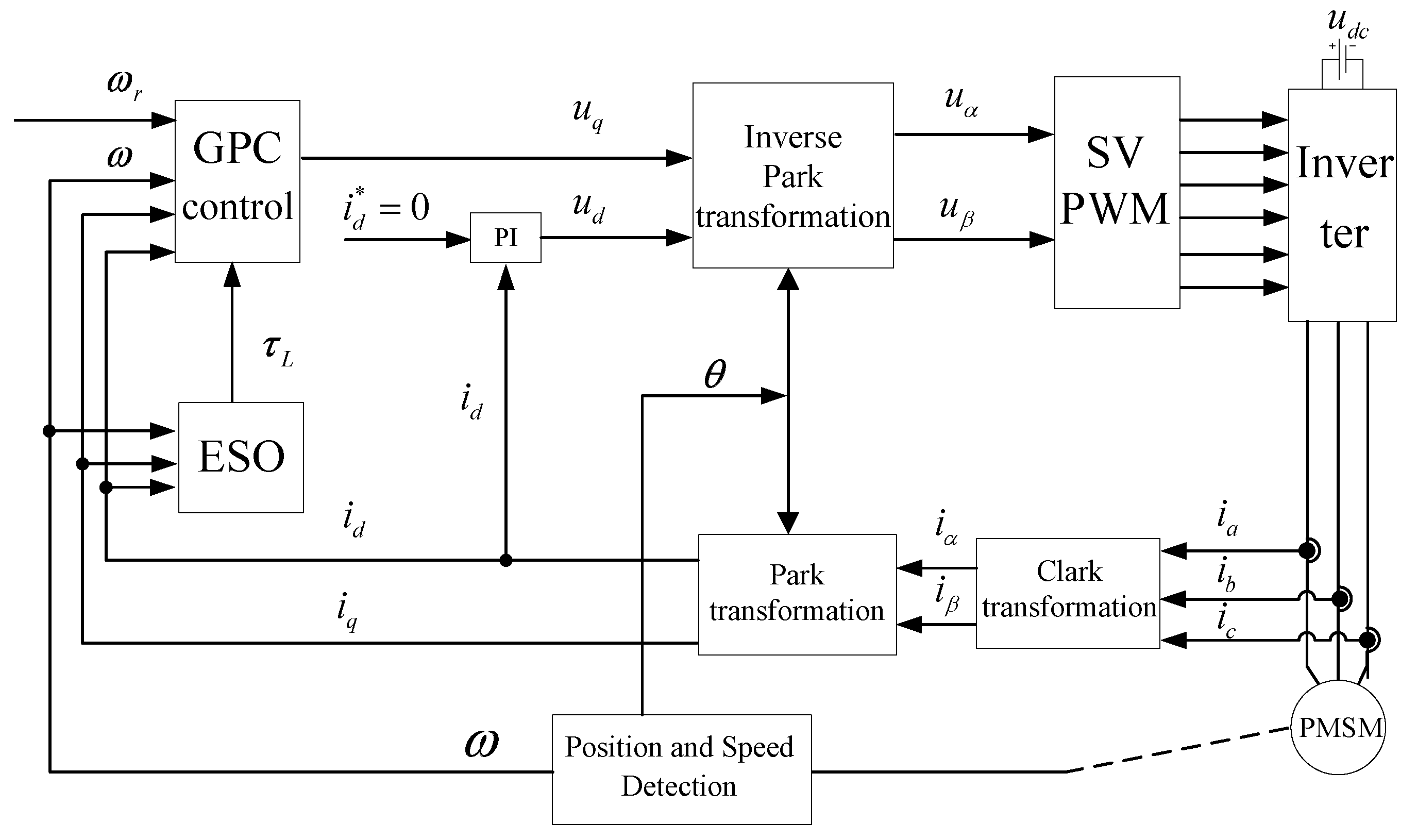
3. The Design of Predictive Controller

To achieve the speed tracking control, a predictive speed controller is designed in this section. Firstly, define the cost function as follows [15].
J = 1 2 0 T r y ^ t + τ y r t + τ T y ^ t + τ y r t + τ d τ
where T r is the predictive horizon, and y ^ t + τ , y r t + τ are respectively represent the predictive output and reference output.
The input relative degree ρ of the output y is defined as the order of its derivative that reveals the input u. According to the nominal system (2), the input relative degree of the output y is equal to 2. The control order r is chosen to zero. Repeated differentiation up to ρ + r times of the output y ^ t with respect to time
y ^ t = L f 0 ω y ^ ˙ t = L f 1 ω y ^ ¨ t = L f 2 ω + L g 1 L f ω u
According to the literature [12], L f 0 ω = ω , L f 1 ω = ω x f x = 0 1 f 1 x f 2 x = f 2 x , L f 2 ω = L f 1 L f 1 ω = n p L d - L q i d + Φ J f 1 x - B J f 2 x , L g 1 L f ω = n p L d - L q i d + Φ L q J , L g 1 L f ω u = n p L d - L q i d + Φ L q J u q .
The Taylor series expansion of the predictive output y ^ t + τ to ρ + r can be expressed as
y ^ t + τ = y ^ t + τ y ^ ˙ t + τ 2 2 y ^ ¨ t
Then, the Equation (5) can be further written as
y ^ t + τ = 1 τ τ 2 2 y ^ t y ^ ˙ t y ^ ¨ t
Assume
Γ τ = 1 τ τ 2 2 , Y ¯ t = y ^ t y ^ ˙ t y ^ ¨ t
Then
y ^ t + τ = Γ τ Y ¯ t
Similarly, the Taylor series expansion of the reference output is
y ^ r t + τ = Γ τ Y ¯ r t
where Y ¯ r t = y r t y ˙ r t y ¨ r t T . Let Γ T r = 0 T r Γ T τ Γ τ d τ , and the elements of the matrix can be represented as
Γ ¯ T r i , j = 1 i 1 ! j 1 ! i + j 1 ! T r i + j 1 , i , j = 1 , 2 , 3
Then the cost function is modified to
J = 1 2 Y ¯ t Y ¯ r t T Γ T r Y ¯ t Y ¯ r t
To make the minimum cost function J, then let J u = 0 [13], the predictive control law can be formulated as
u = G 1 x K M ρ + L f 2 ω y ¨ r
where
G x = L g 1 L ρ 1 ω = L g 1 L f 1 ω = L g 1 n p L d L q i d i q + Φ i q J τ L J B ω J = n p L d L q i d + Φ J L q
M ρ = h x y r t L f 1 ω y r 1 t = ω ω r f 2 x
where ω r is the reference speed. K R 1 × 2 is the first row of matrix Γ ¯ r r 1 Γ ¯ ρ r T , and
Γ ¯ T r = Γ ¯ ρ ρ Γ ¯ ρ r Γ ¯ ρ r T Γ ¯ r r
where Γ ¯ ρ ρ R 2 × 2 , Γ ¯ ρ r R 2 × 1 , Γ ¯ r r R 1 × 1 . Then, K can be get as
K = 10 3 T r 2 5 2 T r
As can be seen in Equation (11), the load torque is included in the predictive control law. When the drive system exists in the load disturbance, it is obvious that the anti-interference performance of the GPC controller will be affected. To solve this problem, a novel extended-state observer is introduced in next section.

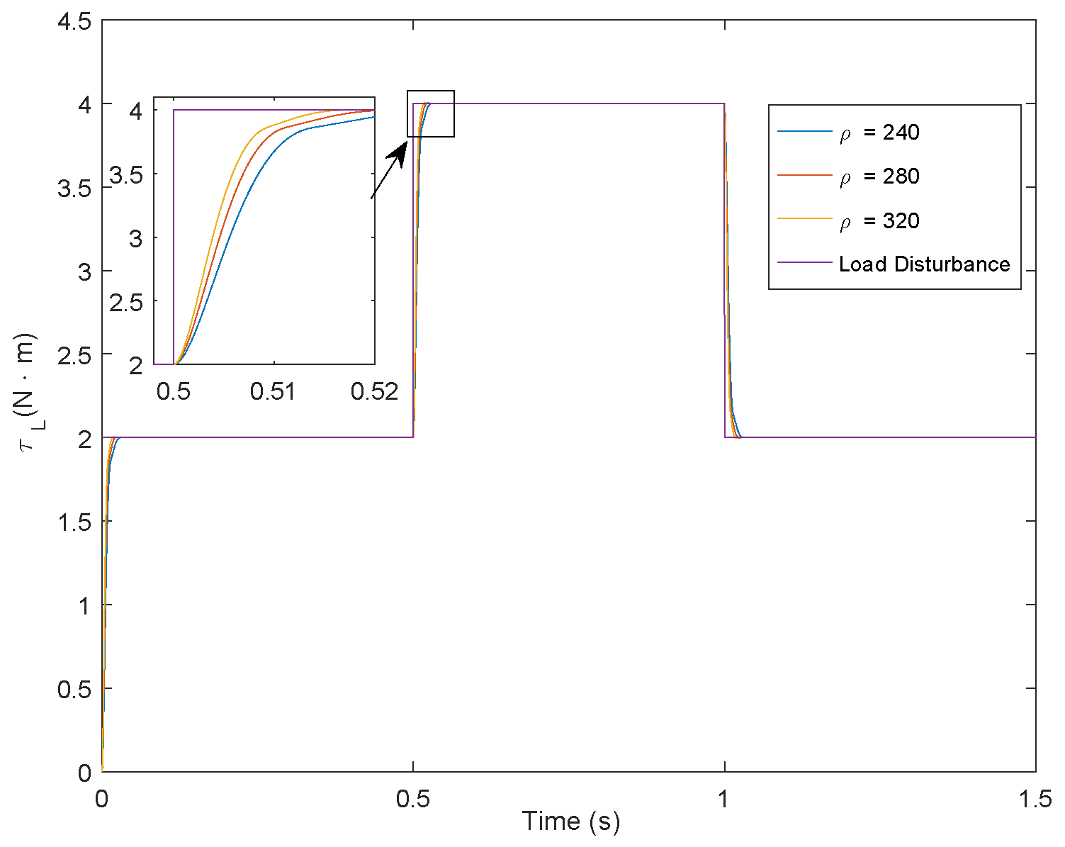
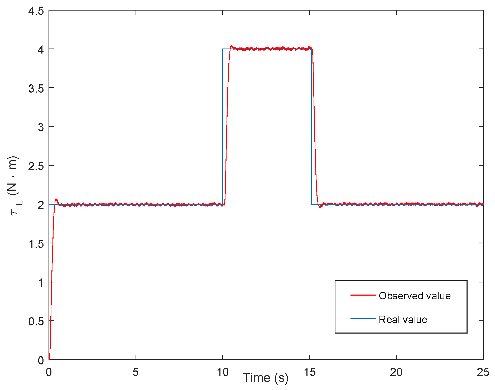
4. The Design of Extended-State Observer

In this section, an estimated load torque τ ^ L is introduced to the controller instead of τ L , and a novel extended-state observer is proposed. The design method of extended-state observer is as follows.
According to the mathematical model of the PMSM in Equation (1)
ω ˙ = n p L d L q i d i q + Φ i q J τ L J B ω J
Define x 1 = ω , x 2 = τ L J , according to the literature [21], then Equation (16) can be written as
x ˙ 1 = x 2 B ω J + n p L d L q i d + Φ J i q x ˙ 2 = 0 + ξ t
where ξ t can be viewed as external disturbance of x ˙ 2 .
Let z 1 and z 2 represent the estimates of x 1 and x 2 , the novel extended-state observer (ESO) is introduced as follows [21].
z ˙ 1 = z 2 B ω J + n p L d L q i d + Φ J i q + ρ e 1 α 1 s i g n e 1 + ρ e 1 β 1 s i g n e 1 + k 1 s i g n e 1 z ˙ 2 = 0 + ρ 2 e 1 α 2 s i g n e 1 + ρ 2 e 1 β 2 s i g n e 1 + k 2 s i g n e 1
where e 1 = ω z 1 , 1 < ρ < + , 0.5 < α 1 < 1 , α 2 = 2 α 1 1 , β 1 = 1 / α 1 , β 2 = 1 / α 1 + β 1 1 , k 1 and k 2 are the gains.
To avoid chattering, the sign function s i g n e 1 in Equation (18) is replaced by a sigmoid function
s i g m f e 1 = 2 1 1 + exp C e 1 , e 1 δ s i g n e 1 , e 1 > δ
where C is a constant and δ is the boundary layer thickness.
To improve the predictive control system performance under load disturbance, a novel ESO is adopted to estimate disturbance. This ensures that the predictive speed controller based on the novel ESO has a good anti-disturbance performance while satisfying the dynamic performance requirements of the control system.

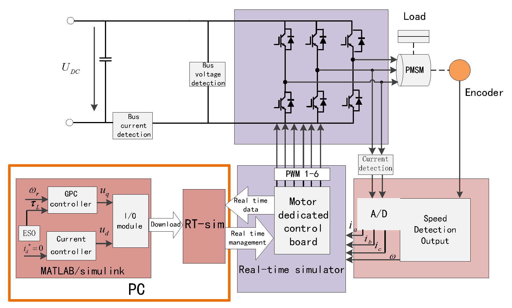
5. Simulation and Experimental Results

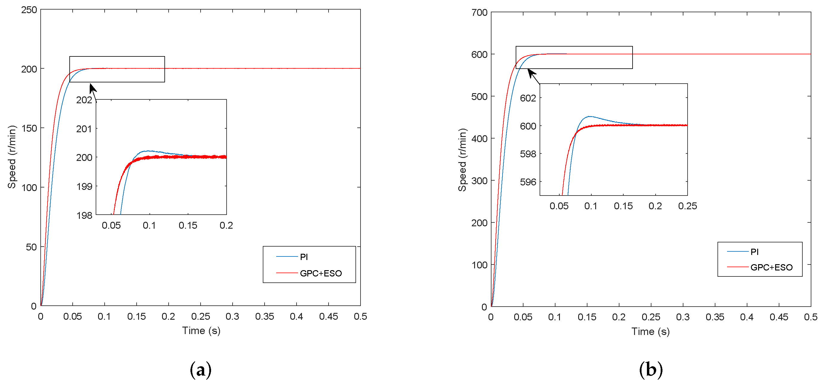
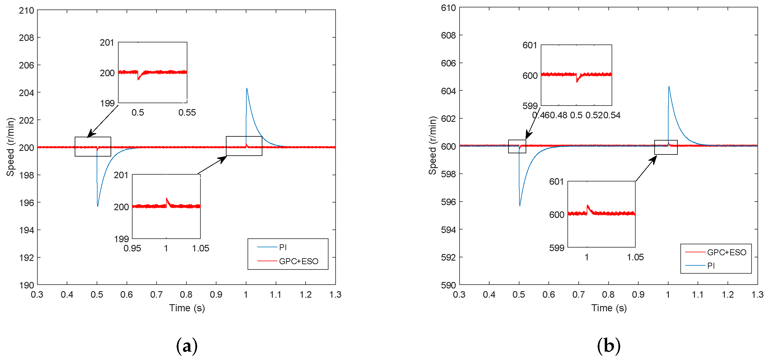
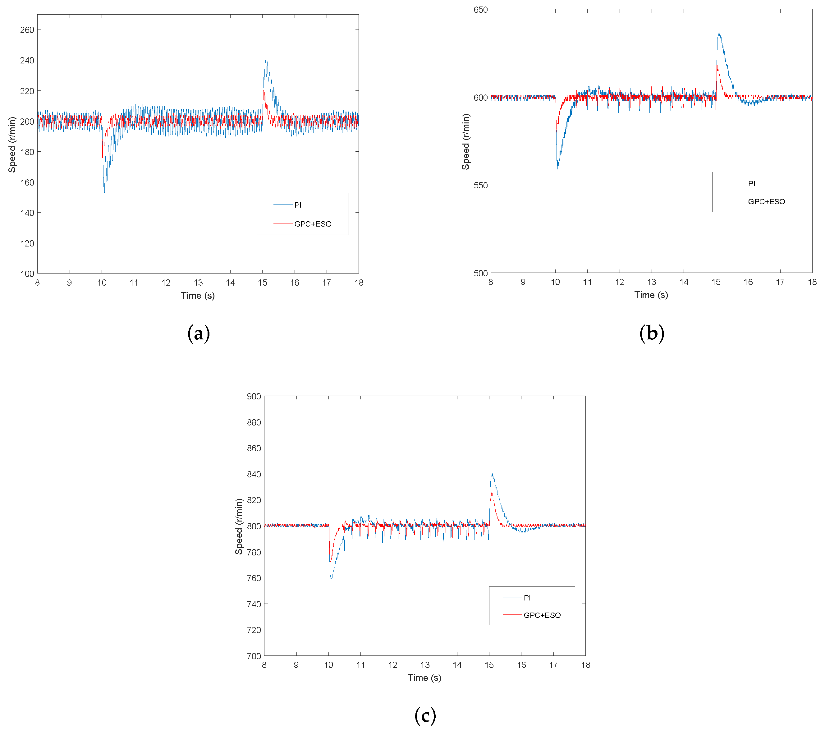
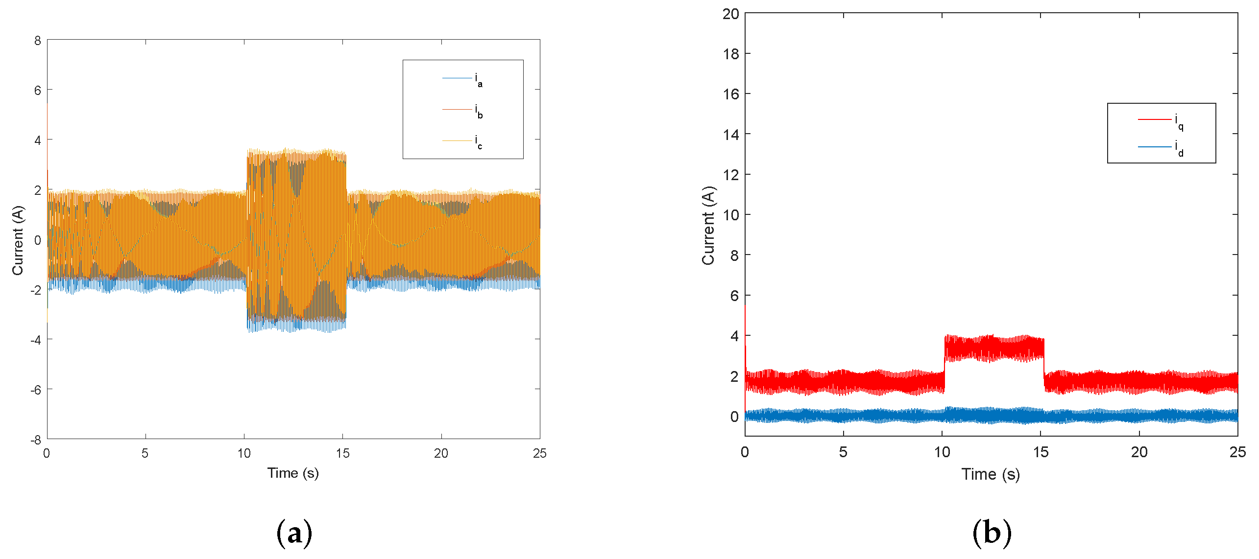
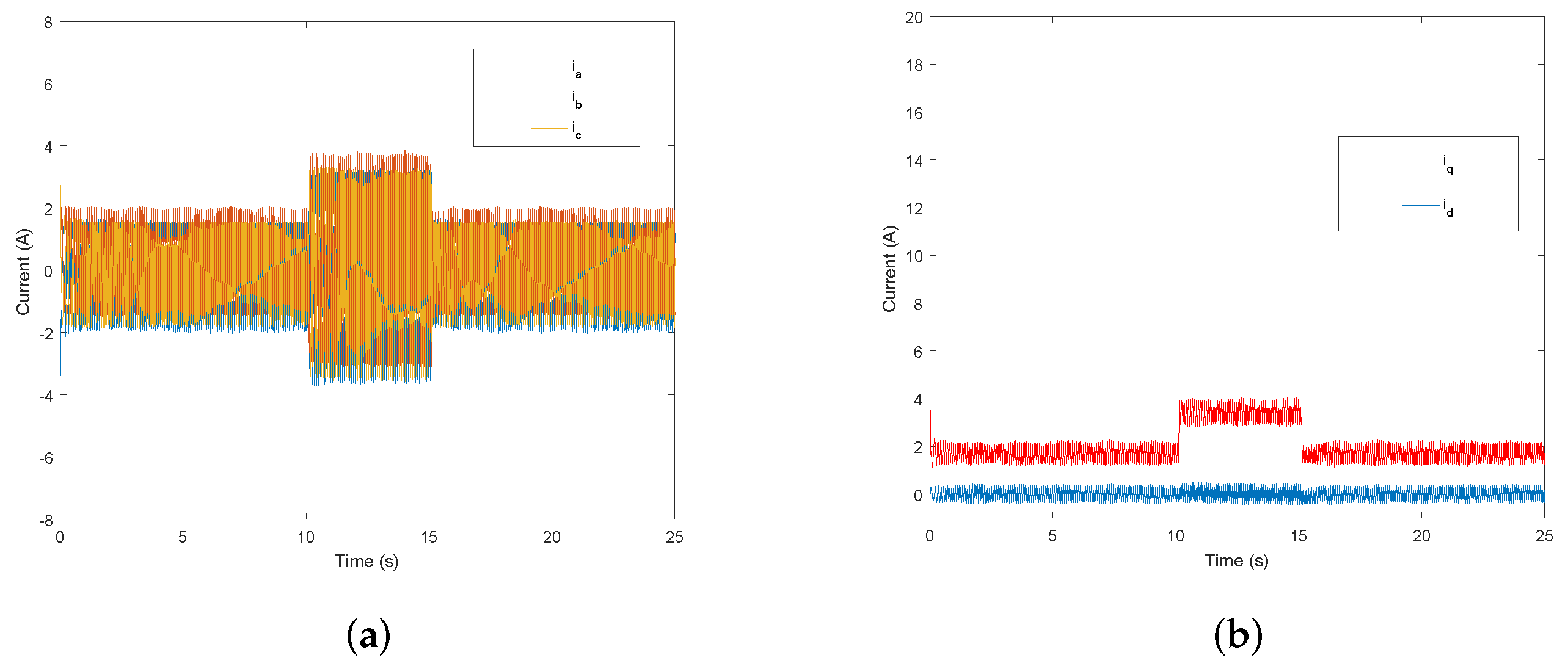
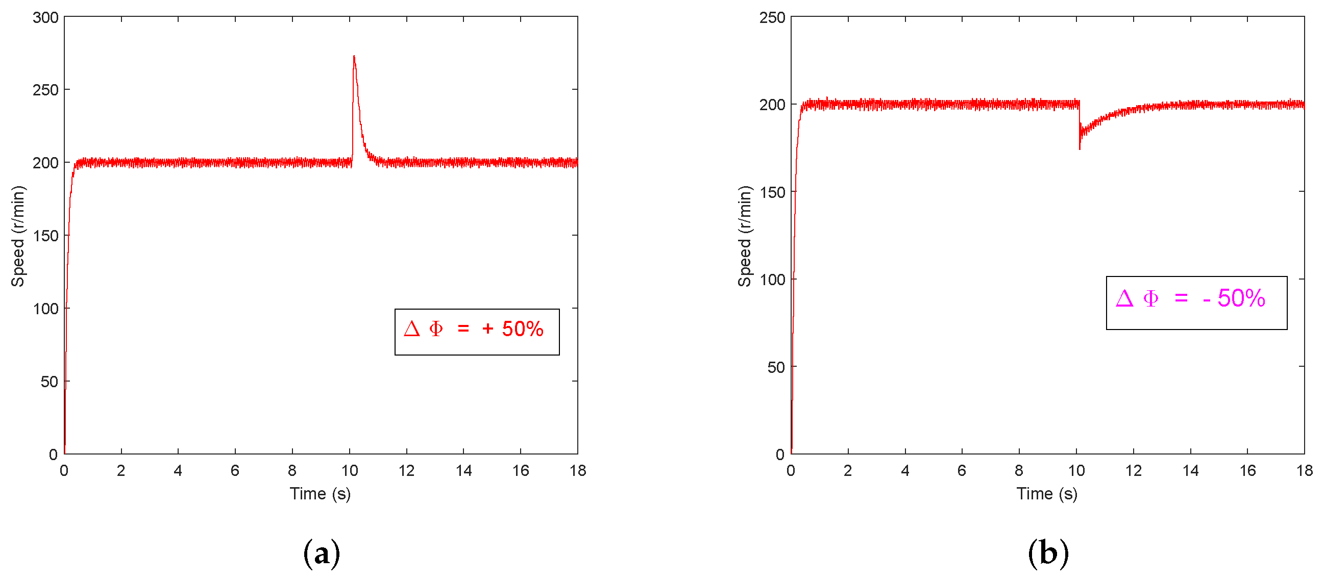
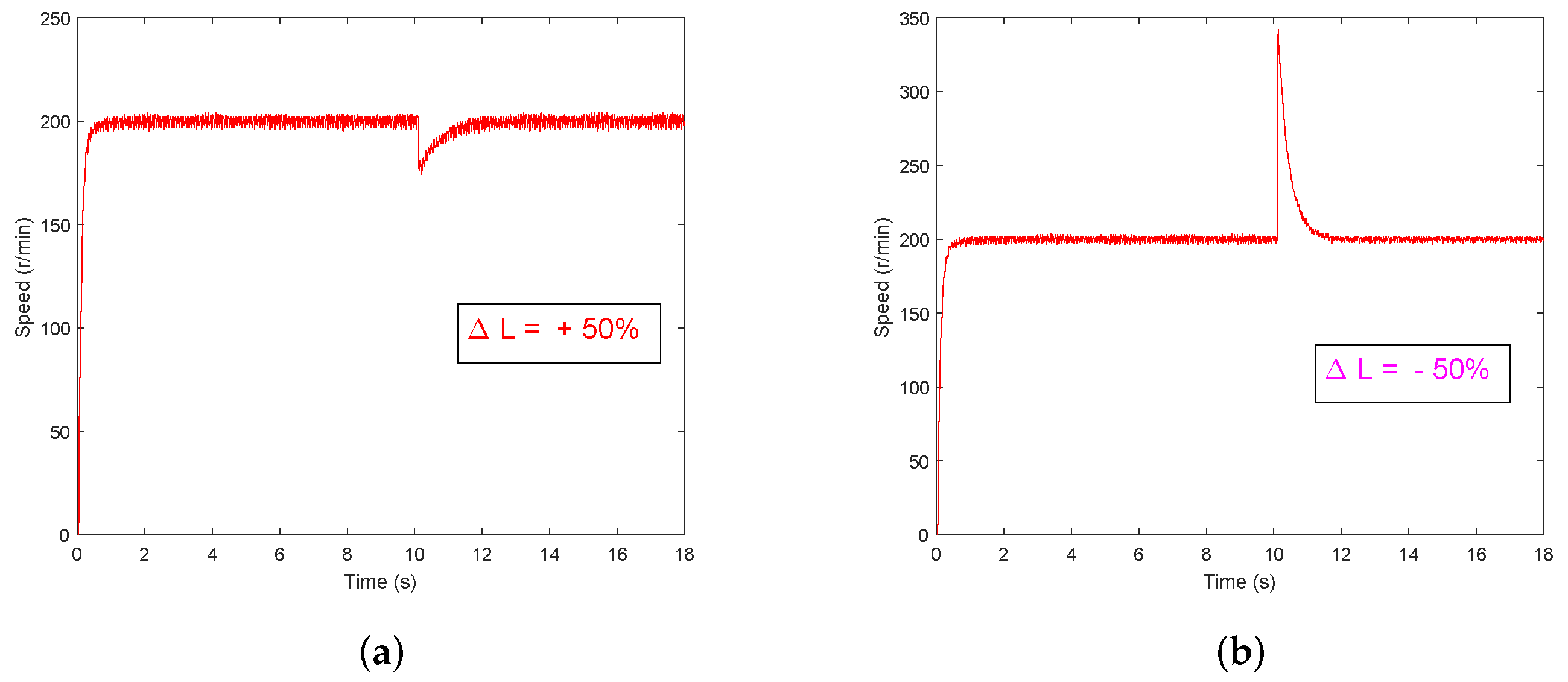
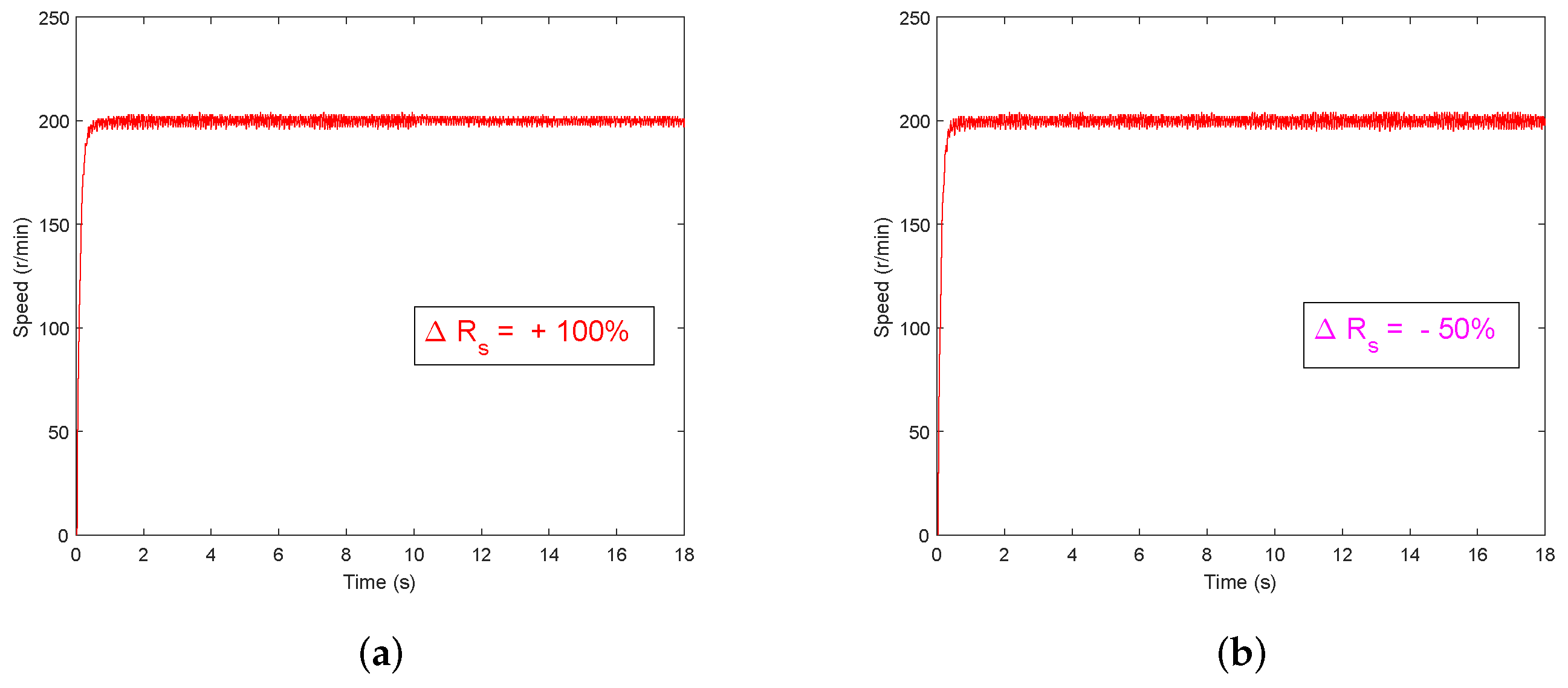
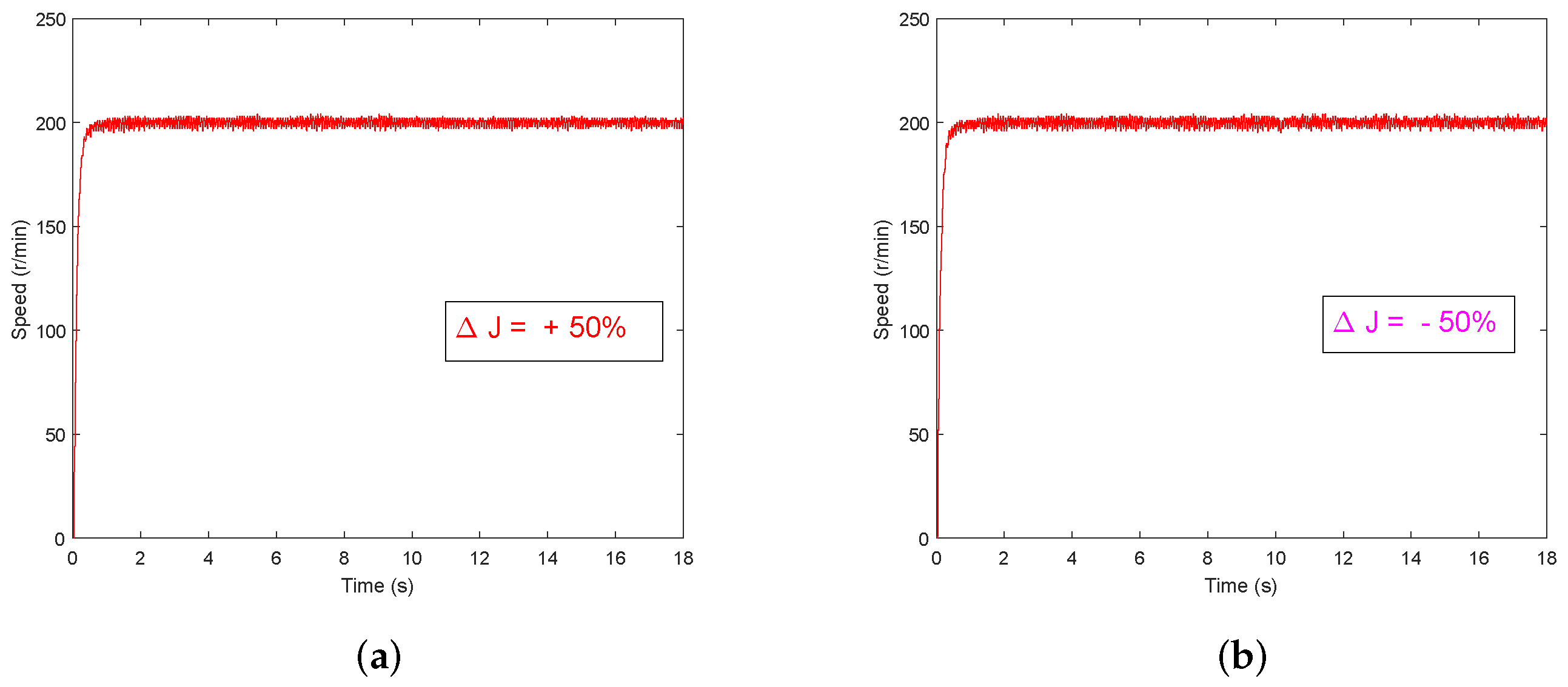
5.1. Simulation Results

To obtain the comparative results and prove the effectiveness of the proposed method, the GPC+ESO and PI controller are compared in simulations. The reference speed is chosen as 200 r/min and 600 r/min, respectively. Simulation was performed on the MTALAB/Simulink platform and the simulation results are presented as follows. The parameters of PMSM for simulation and experiment are shown in Table 1.
The speed response curves of two control methods are shown in Figure 2. As shown in the figures, in different given reference speed, compared with PI method, the GPC+ESO control method has a better speed tracking and no overshoot. It can also be seen that the GPC+ESO method takes less time to reach steady state.
Figure 3 show the simulation curves of the speed response when a load torque τ L = 2 N·m is added at t = 0.5 s and it is removed at t = 1 s. The results clearly show that the GPC+ESO control method has a smaller speed fluctuation and shorter adjust time.
The estimated load torque of the ESO is shown in Figure 4. Given different values of parameter ρ , the tracking speed of load disturbance are also different. In addition, the parameter value should be selected in a certain range for the reason that an excessively big parameter value can also cause overshoot while improving the tracking performance of the ESO.

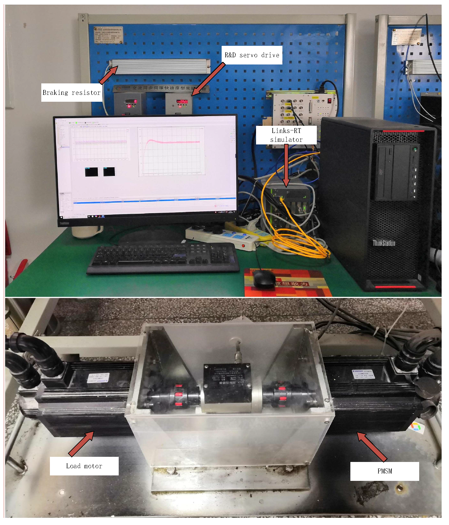
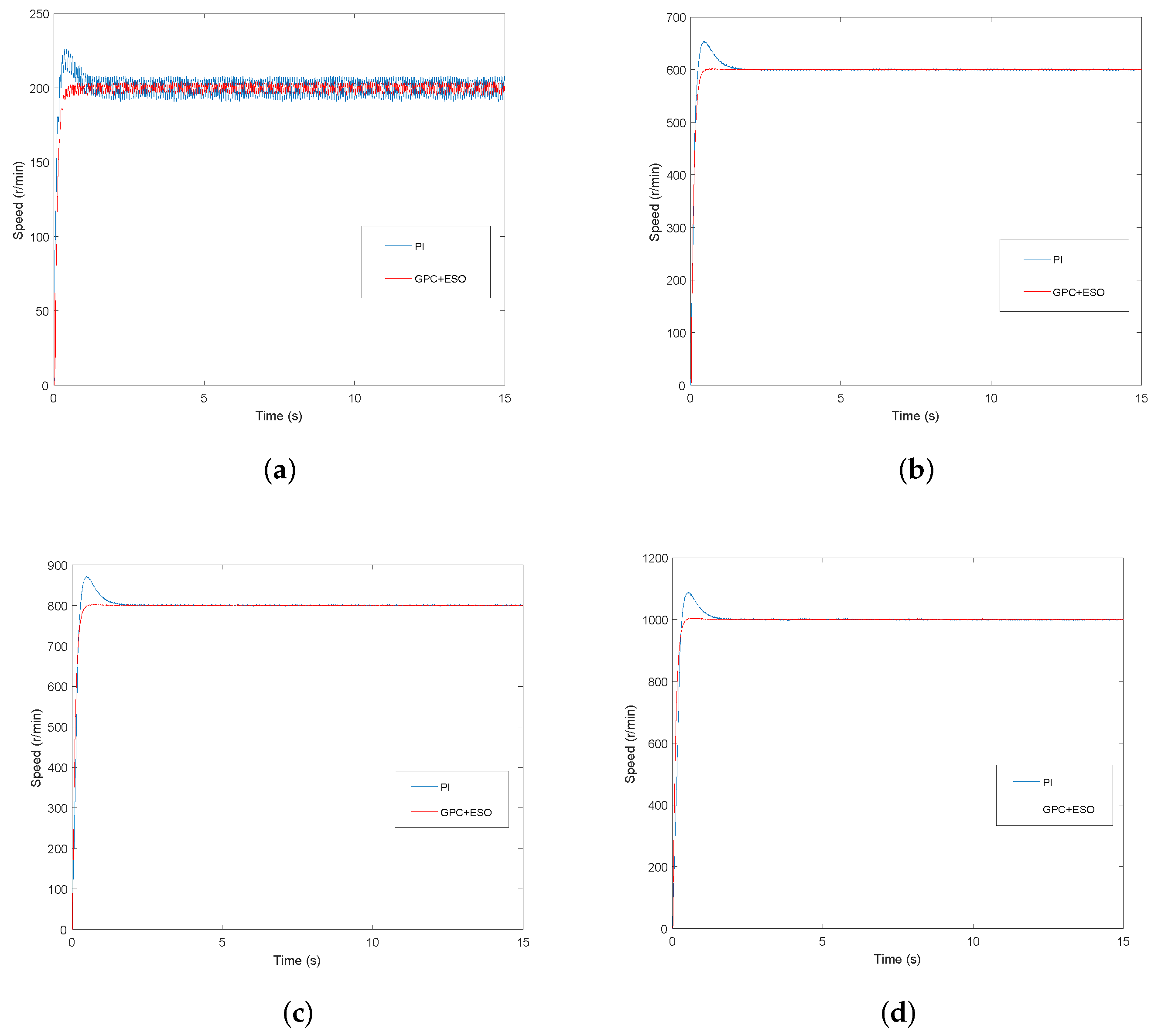
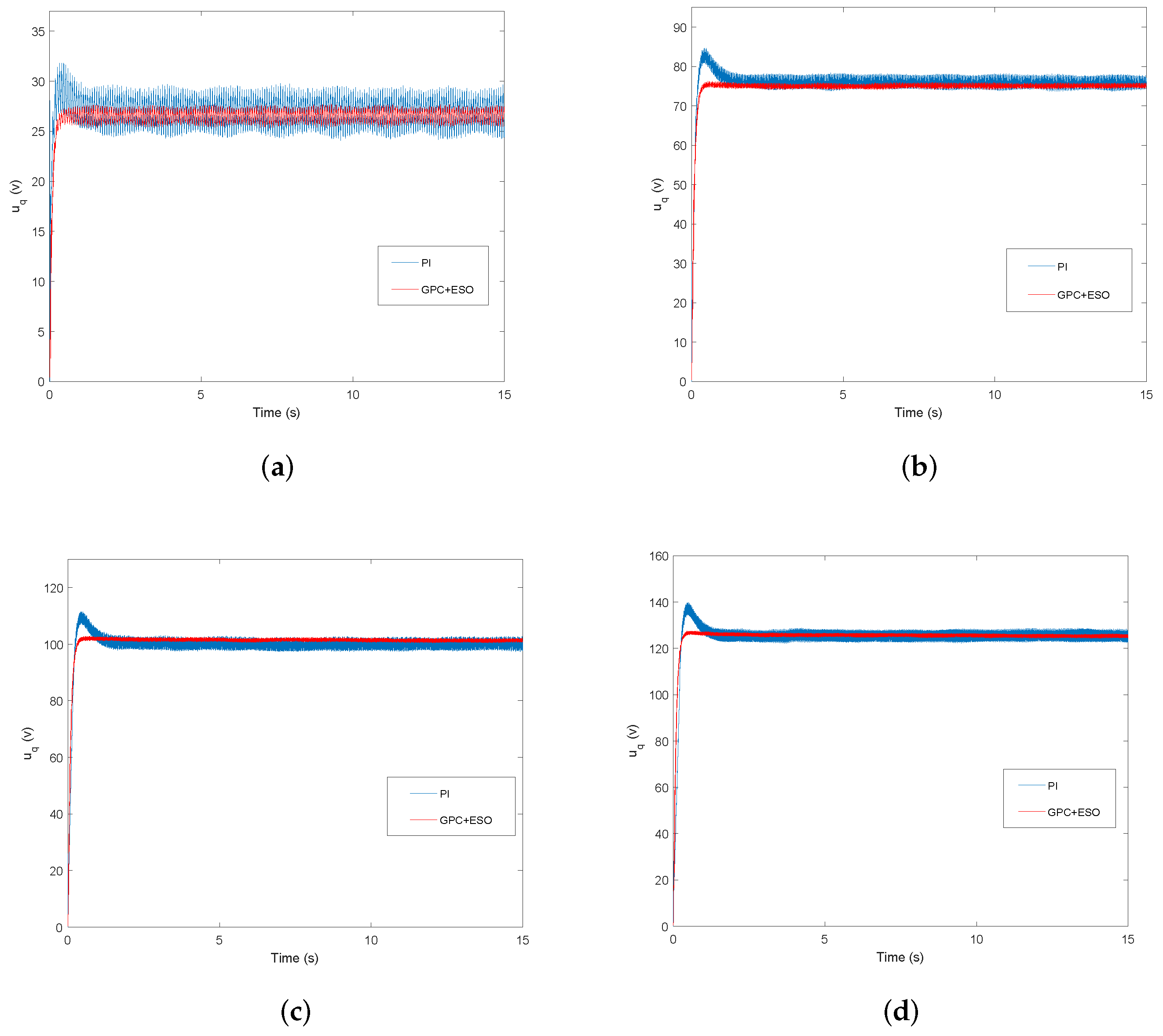
5.2. Experimental Results

The overall experiments are completed with the LINKS-RT rapid prototyping platform. The system used in this paper is a 130MB150A non-salient pole PMSM and the parameters are shown in Table 1. The inverter switching is 10 KHz. Figure 5 shows the hardware and experimental configuration of the PMSM drive and control system. The platform of the experiment is given in Figure 6.
To verify the advantages of the proposed control algorithm, the GPC+ESO method are compared with PI method in speed response and anti-disturbance performance. In the experiment, the different reference speed values are given based on the same control parameters and the integral term is introduced to the controller to reject parameters disturbance. The load torque disturbance and parameter disturbance are added suddenly when the motor reaches steady state, and the load disturbance is removed after a period of time.
The optimal PI control parameters are determined by the trial and error method and given as following. The parameters for the d - axis and q - axis current loop are the same k p = 7, k i = 18, sampling time T s = 0.0001 s. The parameters for the speed loop are given as k p = 0.02, k i = 0.25.
In GPC speed controller, the predictive horizon T r = 0.005, and the parameters for the d - axis current loop are k p = 7, k i = 18. The parameters for the ESO are chosen as ρ = 10 , α 1 = 0.9 , k 1 = k 2 = 1 , C = 40 , and δ = 0.05 .
The reference speed is chosen as n = 200 r/min, n = 600 r/min, n = 800 r/min and n = 1000 r/min, respectively.
In the closed-loop speed regulation experiment of PMSM, the speed response curves at different given reference speed are shown in Figure 7. Figure 7a shows that under the speed command n = 200 r/min, the overshoot of the PI method is about 12.5%(25r), the settling time to the steady state is about 1s. In the same condition, the speed response based on GPC+ESO method has no overshoot and the settling time taken to steady state is approximately 0.5 s. Figure 7b–d also show that compared with PI controller, the GPC+ESO method shows a smaller overshoot and shorter settling time. Figure 8 shows the experimental curves of u q under GPC+ESO and PI method. The results reflect that GPC+ESO speed controller does not need higher voltage to achieve the reference speed. In addition, the voltage u q has a smaller fluctuation in the GPC+ESO method. From above figures, it can be concluded that the GPC+ESO method can enhance the dynamic performance of the PMSM drive systems.
Then, to verify the performance of the proposed controller under sudden load disturbance impact, experiments have also been completed in this part. The experimental results are shown in Figure 9, Figure 10 and Figure 11. As can be seen from Figure 9, when the motor is running at a steady state of n = 200 r/min, a load disturbance τ L = 2 N·m is added at t = 10 s and it is removed at t = 15 s. It can be observed that the proposed method has a better anti-disturbance performance than PI control, and when an abrupt load is added, the fluctuation of the GPC+ESO method is about 24r, 20r, and 29r, respectively at 200 r/min, 600 r/min and 800 r/min. The recovering time against disturbance is about 0.5 s, 0.6 s and 0.45 s, respectively at 200 r/min, 600 r/min and 800 r/min, faster than PI control. After a period of time, the abrupt load is removed. To further illustrate the strengths of the proposed method, this paper introduces the comparison of disturbance rejection performance from the two controllers under different reference speeds. The complete results are shown in Table 2.
Figure 10 and Figure 11 show the response curves of the current with load disturbance under n = 200 r/min. The three-phase current response curves of GPC+ESO and PI method are shown in Figure 10a and Figure 11a, respectively. The d-q axis current curves of GPC+ESO and PI method are shown in Figure 10b and Figure 11b, respectively.
The estimated load disturbance of the ESO is shown in Figure 12, and the observed load torque value was used for the GPC controller which can improve the robustness of the system. The Figure 12 shows that the proposed ESO can estimate the external load disturbance accurately and has small fluctuation.
From these experimental curves, it is evident that the predictive speed-control algorithm based on a novel extended-state observer for PMSM drives is practicable. It can also ensure and improve the ability to reject load disturbance while possessing a good dynamic performance of the control system.
In the long-term operation of the motor, the motor parameters will change with the increase of the temperature. It is necessary to verify the ability of the proposed controller under parameter disturbance.
Suppose x = x o 1 + Δ x , x = R s , J , L , Φ , where x o represents the rated parameter values of PMSM, Δ x represents the parameter disturbance. All the parameter disturbances are applied at 10s. Under the parameter disturbance, the experimental results are shown in Figure 13, Figure 14, Figure 15 and Figure 16.
Figure 13 and Figure 14 show the motor speed curves under the GPC+ESO controller with a sudden change of rotor flux value and inductance value, respectively. Figure 13 shows that the fluctuation of the motor under the GPC+ESO method is 74r and 26r, respectively in case of rotor flux value increases 50% and decreases 50%. The recovering time to the reference speed is about 1 s and 3.8 s, respectively in case of rotor flux value increases 50% and decreases 50%. The specific experimental results are presented in Table 3.
Figure 15 and Figure 16 show the motor speed curves under the GPC+ESO controller with a sudden change of stator resistance value and moment of inertia value, respectively. Figure 15a shows that the speed ripple of the motor under the GPC+ESO method is reduce when the stator resistance value increases 100%. Figure 15b shows that the speed ripple of the motor under the GPC+ESO method is increase when the stator resistance value decreases 50%. Figure 16 shows that the motor speed response curve has no significant variety when the moment of inertia value changes.
It can be observed that in all experimental results, the proposed speed controller has strong robustness for the parameter disturbance in a certain range.

6. Conclusions

In this paper, a predictive speed-control algorithm based on a novel extended-state observer for PMSM drives is proposed. Firstly, the design and implementation of a speed tracking controller based on GPC control is introduced for PMSM. Then, to further improve the disturbance rejection ability of the control system, a novel extended-state observer is used to estimate the load torque, and the estimated load torque is introduced to the GPC controller. Compared with PI control method, the simulation and experiment results show that the proposed GPC+ESO control method can obtain a superior dynamic performance with good external and internal disturbances rejection performance, fast speed tracking response, and strong robustness.

Author Contributions

Y.Z. completed all the experiments and wrote the manuscript, X.L. designed the proposed control strategy and conceived the structure of the paper, X.L. and Q.Z. completed the analysis of the simulation and experimental results.

Funding

This research was funded by the National Natural Science Foundation of China under Grant 61703222, in part by the China Postdoctoral Science Foundation under Grant 2018M632622.

Conflicts of Interest

The authors declare no conflict of interest.

References

  1. Aghili, F. Optimal Feedback linearization control of interior PM synchronous motors subject to time-varying operation conditions minimizing power loss. IEEE Trans. Ind. Electron. 2018, 65, 5414–5421. [Google Scholar] [CrossRef]
  2. Hu, J.; Qiu, Y.; Lu, H. Adaptive robust nonlinear feedback control of chaos in PMSM system with modeling uncertainty. Appl. Math. Model. 2016, 40, 8265–8275. [Google Scholar] [CrossRef]
  3. Chen, J.; Yao, W.; Ren, Y.; Wang, R.; Zhang, L.; Jiang, L. Nonlinear adaptive speed control of a permanent magnet synchronous motor: A perturbation estimation approach. Automatica 2017, 76, 143–152. [Google Scholar] [CrossRef]
  4. Qian, J.; Ji, C.; Pan, N.; Wu, J. Improved sliding mode control for permanent magnet synchronous motor speed regulation system. Appl. Sci. 2018, 8, 2491. [Google Scholar] [CrossRef]
  5. Liu, X.; Yu, H.; Yu, J.; Zhao, L. Combined Speed and Current Terminal Sliding Mode Control With Nonlinear Disturbance Observer for PMSM Drive. IEEE Access 2018, 6, 29594–29601. [Google Scholar] [CrossRef]
  6. Ouledali, O.; Meroufel, A.; Bentouba, S. Direct torque fuzzy control of PMSM based on SVM. IEEE Trans. Ind. Electron. 2015, 74, 1314–1322. [Google Scholar] [CrossRef]
  7. Yu, J.; Chen, B.; Yu, H.; Zhao, L.; Lin, C. Neural networks-based command filtering control of nonlinear systems with uncertain disturbance. Inf. Sci. 2018, 426, 50–60. [Google Scholar] [CrossRef]
  8. Wangm, M.S.; Tsai, T.M. Sliding mode and neural network control of sensorless PMSM controlled system for power consumption and performance improvement. Energies 2017, 10, 1780. [Google Scholar] [CrossRef]
  9. Sun, T.; Pan, Y.; Zhang, J.; Yu, H. Robust model predictive control for constrained continuous-time nonlinear systems. Int. J. Control 2018, 91, 1–16. [Google Scholar] [CrossRef]
  10. Chai, S.; Wang, L.; Rogers, E. A cascade MPC control structure for a PMSM with speed ripple minimization. IEEE Trans. Ind. Electron. 2013, 60, 2978–2987. [Google Scholar] [CrossRef]
  11. Bolognani, S.; Bolognani, S.; Peretti, L.; Zigliotto, M. Design and Implementation of Model Predictive Control for Electrical Motor Drives. IEEE Trans. Ind. Electron. 2009, 56, 1925–1936. [Google Scholar] [CrossRef]
  12. Errouissi, R.; Ouhrouche, M.; Benzaioua, A. Robust nonlinear predictive controller for multivariable nonlinear systems with different relative degree. In Proceedings of the IEEE/ASME International Conference on Advanced Intelligent Mechatronics, Montreal, ON, Canada, 6–9 July 2010; pp. 1231–1237. [Google Scholar]
  13. Chen, W.; Ballance, D.; Gawthrop, P. Optimal control of nonlinear systems: A predictive control approach. Automatica 2003, 39, 633–641. [Google Scholar] [CrossRef]
  14. Errouissi, R.; Ouhrouche, M. Nonlinear predictive controller for a permanent magnet synchronous motor drive. Math. Comput. Simul. 2010, 81, 394–406. [Google Scholar] [CrossRef]
  15. Errouissi, R.; Ouhrouche, M. Robust Cascaded Nonlinear Predictive Control of a Permanent Magnet Synchronous Motor With Antiwindup Compensator. IEEE Trans. Ind. Electron. 2012, 59, 3078–3088. [Google Scholar] [CrossRef]
  16. Chakrabarty, A.; Corless, M.; Buzzard, G.T.; Żak, S.H.; Rundell, A.E. State and unknown input observers for nonlinear systems with bounded exogenous inputs. IEEE Trans. Autom. Control 2017, 62, 5497–5510. [Google Scholar] [CrossRef]
  17. Sariyildiz, E.; Ohnishi, K. Stability and robustness of disturbance-observer-based motion control systems. IEEE Trans. Ind. Electron. 2015, 62, 414–422. [Google Scholar] [CrossRef]
  18. Deng, Y.; Wang, J.; Li, H.; Liu, J.; Tian, D. Adaptive sliding mode current control with sliding mode disturbance observer for PMSM drives. ISA Trans. 2019, 88, 113–126. [Google Scholar] [CrossRef] [PubMed]
  19. Qian, J.; Xiong, A.; Ma, W. Extended state observer-based sliding mode control with new reaching law for PMSM speed control. Math. Probl. Eng. 2016, 2016, 1–10. [Google Scholar] [CrossRef]
  20. Gonzalez, A.; Balaguer, V.; Garcia, P.; Cuenca, A. Gain-scheduled predictive extended state observer for time-varying delays systems with mismatched disturbances. ISA Trans. 2018, 84, 206–213. [Google Scholar] [CrossRef] [PubMed]
  21. Xiong, S.; Wang, W.; Liu, X.; Chen, Z.; Wang, S. A novel extended state observer. ISA Trans. 2015, 58, 309–317. [Google Scholar] [CrossRef] [PubMed]
Figure 1. Control system diagram of the PMSM drive systems.
Applsci 09 02575 g001
Figure 2. Simulation curves of speed response. (a) n = 200 r/min; (b) n = 600 r/min.
Applsci 09 02575 g002
Figure 3. Simulation curves of speed response under the load disturbance. (a) n = 200 r/min; (b) n = 600 r/min.
Applsci 09 02575 g003
Figure 4. Simulation curve of load disturbance tracking based on the ESO.
Applsci 09 02575 g004
Figure 5. The experimental configuration of the PMSM drive and control system.
Applsci 09 02575 g005
Figure 6. Experimental platform.
Applsci 09 02575 g006
Figure 7. Experimental speed curves under the GPC+ESO and PI method. (a) n = 200 r/min; (b) n = 600 r/min; (c) n = 800 r/min; and (d) n = 1000 r/min.
Applsci 09 02575 g007
Figure 8. Experimental response curves of uq under the GPC+ESO and PI method. (a) n = 200 r/min; (b) n = 600 r/min; (c) n = 800 r/min; and (d) n = 1000 r/min.
Applsci 09 02575 g008
Figure 9. Experimental speed curves when a sudden load is added or removed. (a) n = 200 r/min; (b) n = 600 r/min and (c) n = 800 r/min.
Applsci 09 02575 g009
Figure 10. Experimental current curves based on GPC+ESO method under load disturbance. (a) three-phase current response curves; (b) d-q axis current response curves.
Applsci 09 02575 g010
Figure 11. Experimental current curves based on PI method under load disturbance. (a) three-phase current response curves; (b) d-q axis current response curves.
Applsci 09 02575 g011
Figure 12. Experimental curve of load disturbance tracking based on the ESO.
Applsci 09 02575 g012
Figure 13. Speed response curves under GPC+ESO method with a sudden change of rotor flux value. (a) ΔΦ = +50%; (b) ΔΦ = −50%.
Applsci 09 02575 g013
Figure 14. Speed response curves under GPC+ESO method with a sudden change of inductance value. (a) ΔL = +50%; (b) ΔL = −50%.
Applsci 09 02575 g014
Figure 15. Speed response curves under GPC+ESO method with a sudden change of stator resistance value. (a) ΔRs = +100%; (b) ΔRs = −50%.
Applsci 09 02575 g015
Figure 16. Speed response curves under GPC+ESO method with a sudden change of moment of inertia value. (a) ΔJ = +50%; (b) ΔJ = −50%.
Applsci 09 02575 g016
Table 1. Parameters of PMSM.
DescriptionValueUnit
rated speed1000r/min
rated torque14.5N·m
stator resistance1.84 Ω
d-axis inductance6.65mH
q-axis inductance6.65mH
rotor flux0.32Wb
moment of inertia0.0027Kg·m 2
Table 2. Comparisons of disturbance rejection performance.
Control MethodsPIGPC+ESOPIGPC+ESOPIGPC+ESO
n = 200 r/min n = 600 r/min n = 800 r/min
Speed fluctuation when a sudden load is added (r·min)−43−24−39−20−39−29
Speed fluctuation when a sudden load is removed (r·min)+40+20+34+18+38+26
speed adjustment time when a sudden load is added (s)10.31.50.41.70.4
speed adjustment time when a sudden load is removed (s)1.30.51.80.61.80.45
Table 3. The internal disturbance rejection performance.
Δ Φ = + 50 % Δ Φ = 50 % Δ L = + 50 % Δ L = 50 %
Speed fluctuation (r/min)+74−26−25+143
speed adjustment time (s)13.821

