Article

Durability of Functionalized Carbon Structures with Optical Fiber Sensors in a Highly Alkaline Concrete Environment

1
Hannover Centre for Optical Technologies (HOT), Leibniz University Hannover, 30167 Hannover, Germany
2
School of Engineering and the Built Environment, Edinburgh Napier University, Edinburgh EH10 5DT, UK
3
Saxon Textile Research Institute (STFI), 09125 Chemnitz, Germany
4
Materialforschungs-und-Prüfanstalt an der Bauhaus-Universität Weimar (MFPA), 99423 Weimar, Germany
5
Cluster of Excellence PhoenixD, Leibniz University Hannover, Welfengarten 1, 30167 Hannover, Germany
*
Author to whom correspondence should be addressed.
Appl. Sci. 2019, 9(12), 2476; https://doi.org/10.3390/app9122476
Submission received: 4 May 2019 / Revised: 28 May 2019 / Accepted: 12 June 2019 / Published: 18 June 2019

Abstract

:
The paper presents an investigation into the durability of functionalized carbon structures (FCS) in a highly alkaline concrete environment. First, the suitability of optical fibers with different coatings—i.e., acrylate, polyimide, or carbon—for the FCS was investigated by subjecting fibers with different coatings to micro/macro bending and a 5% sodium hydroxide (NaOH) (pH 14) solution. Then, the complete FCS was also subjected to a 5% NaOH solution. Finally, the effects of spatial variation of the fiber embedded in the FCS and the bonding strength between the fiber and FCS was evaluated using different configurations —i.e., fiber integrated into FCS in a straight line and/or with offsets. All three coatings passed the micro/macro bending tests and show degradation after alkaline exposure, with the carbon coating showing least degradation. The FCS showed relative stability after exposure to 5% NaOH. The optimum bonding length between the optical fiber and the carbon filament was found to be ≥150 mm for adequate sensitivity.

1. Introduction

The replacement of conventional techniques used for structural health monitoring (SHM) based on electrical means (i.e., strain gauges for strain measurement) [1,2] with fiber optic sensors (FOSs) has seen increased popularity over the last decade due to the number of advantages they possess over conventional schemes. The glass (silica) construction of fiber optics renders them robust and capable of withstanding harsh and corrosive environments [3,4,5,6,7]. The low attenuation of optical glass fiber enables them to be interrogated over a long length (i.e., several 100 s of kilometers). The fact that a multitude of sensors can be multiplexed within a single strand of fiber together with the possibility of utilizing a wider bandwidth makes FOSs most suitable for applications that require extraction of data from a vast amount of sensing elements such as those required for SHM of large structures [8,9,10,11,12]. Moreover, the sensors, although multiplexed along one fiber, have the capability to monitor several parameters simultaneously and thus provide the opportunity to assess not only, for example, the strain levels but also other chemical parameters, such as humidity and pH. Thus, it is evident from the current literature that the utilization of FOSs for SHM has not yet reached its full potential and requires further investigations paired with advances in chemical and materials engineering. In fact, the recent merging between textile and sensor engineering has seen rapid developments in wearable technology, especially in the biomedical engineering field [13,14,15], which provides much motivation for adopting advances in chemical/textile engineering in other areas of sensing, i.e., SHM.
Conventional FOSs used for SHM have been mainly grating-based and require adequate attachment of the sensor region to the structure. This had been mainly achieved using binding agents, such as epoxy [16,17]. The installation of such a sensing scheme not only requires specialist trained personnel in fiber optics to carry out the installation, but also, the accuracy of the sensing mechanism relies heavily on the efficiency of the intermediate transfer agent, i.e., epoxy. In addition, the hassle of having to somehow attach the fiber on the structure makes it unattractive to civil engineers, who are not used to dealing with cables that are of micro-meter-diameter-level dimension [18]. An ideal solution would be to embed the sensors on to the strengthening element of the structure itself, which saves time and costs, increasing the efficiency of the overall scheme.
Projects such as the Carbon Concrete Composite (C3) initiative in Germany aim to replace traditional steel reinforced concrete (SRC) as a building material with carbon reinforced concrete (CRC) [19]. The inherent characteristics of CRC possess a considerable number of advantages over conventional SRC, i.e., light weight, lifespan, thermal and electrical conductivity properties, flexibility of fabrication, efficiency and immunity to risk of corrosion. Further, CRC can be constructed in thin layers with high tensile strength, which makes it most suitable for intelligent building construction. The direct integration of FOSs into CRC forms an advanced field of research, which needs careful investigation into the durability of the said integration and thus its practicality in long-term use. To this end, it is of vital importance to evaluate whether the physical construction of the optical glass fiber (preferably single-mode fiber with acrylate, polyimide or carbon coating) is able to withstand its host environment, i.e., concrete.
The combination of the high alkaline environment in concrete and the concrete mechanical stress adversely affects not only the integrity of the optical fiber but the strength of the bonding between the carbon fiber reinforcement and the optical fiber. In a worst-case scenario, the optical fiber can be damaged to a level of non-operation. The sensing region must not detach from the structure/reinforcement as a result of mechanical stress or be decomposed due to the high alkaline surrounding. These considerations emphasize the level of attention needed to evaluate the mechanical properties of the optical fiber embedded into concrete.
Over the past few decades, much work has been focused on the survival of glass in high alkaline concrete environments [20], leading to embedding FOSs in concrete to evaluate its durability [21,22]. Research has shown that polymeric coatings increase the durability of optical fibers in concrete [21]. In particular, optical silica glass fibers with high alkaline resistance were obtained by coating them with polyetherimide [23], fluorine-polymer [24], and carbon coating [25].
Previous work by the authors presented a Functionalized Carbon Structure (FCS), where fiber optic sensors were “woven” into carbon fiber reinforcement polymer (CFRP) strands in order to evaluate the bonding strength between the sensor element and concrete [26]. This was focused on FOSs embedded in FCSs and textile net structures (TNSs) based on alkaline resistant glass. This work was further extended to embed FCSs in concrete blocks to evaluate the performance of the FOSs and the detailed analysis on the performance and the results can be found elsewhere [27]. However, when FCSs are embedded into concrete structures, the highly alkaline environment would degrade the FCS, thus limiting its life-span and operation. The strength of resistance to these highly alkaline environments would depend on the type of fiber used and the material of the protective-coating surrounding the fiber, i.e., acrylate, polyimide, or carbon. To this end, the paper presented here consists of a detailed analysis on the durability of FCS embedded with optical glass fiber sensors in a highly alkaline concrete environment. In addition, the spatial variation of the optical fiber inside the FCS was also analyzed to evaluate its effects on the bonding between the optical glass fiber and FCS.

2. Materials and Methods

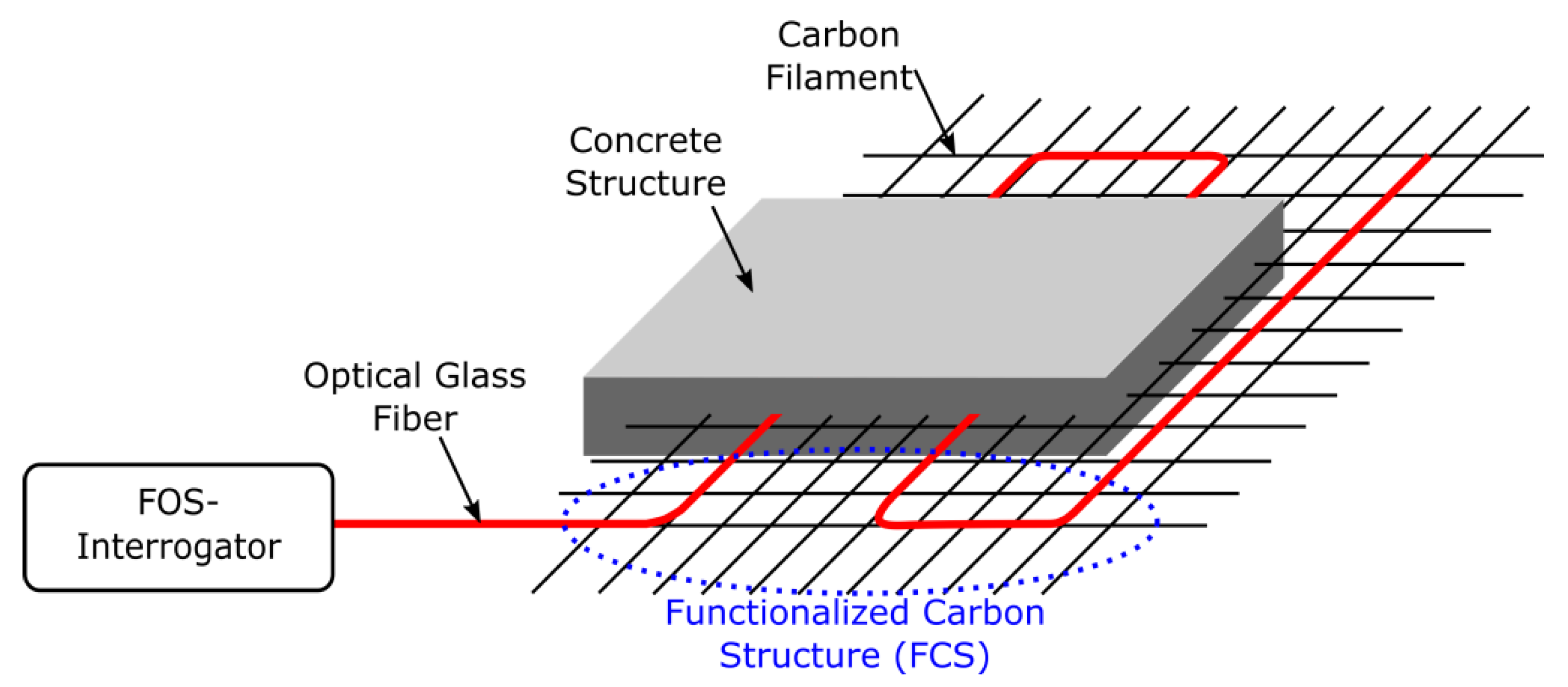
2.1. Fabrication of one Dimensional (1D) and Two Dimensional (2D)-FCS

Figure 1 depicts the experimental concept of embedding the FCS in concrete for its SHM, as evaluated in the work presented herewith.
The fabrication of the FCS has already been reported [26,27]. The fabrication technique was developed at the Saxon Textile Research Institute (STFI) in Chemnitz, Germany and is based on embroidering carbon fibers and optical glass fibers simultaneously in a grid-like format on a polyvinyl alcohol (PVA) nonwoven substrate. PVA was chosen for this purpose since it can be easily dissolved in hot water as well as it protects the FCS. The advantage of this fabrication technique is that depending on the application, tailored FCS can be produced with various forms of lattice structures, multiple layers of carbon filaments as well as with different configuration of the optical glass fibers inside the FCS. The latter is, in particular, interesting to optimize the bond between the textile carbon structure and the optical glass fiber and thus to optimize the sensor response.
In order to explore the sensor response and the resistance to highly alkaline concrete environment of the FCS, one dimensional (1D) and two dimensional (2D) FCSs have been fabricated. The 1D-FCSs have been fabricated, in particular, to investigate the sensitivity of the FCS to the highly alkaline concrete environment. To do this, a single strand of carbon filaments of 400, 800 or 1600 tex have been simultaneously embroidered with SM fiber Corning ClearCurve (CC) on the PVA nonwoven substrate. After dissolving the PVA, the length of each 1D-FCS was measured to be 300 mm.
The 2D-FCSs have been fabricated in order to evaluate whether the shape of the optical glass fiber inside the FCS has an impact on the sensor response. To explore this, FCSs have been fabricated with different configurations of the optical glass fiber, as shown in Figure 2. In total, the fiber is integrated into the FCS in three different configurations. In the first case, (a) the fiber is straight; in the second case, (b) the fiber is placed with a slight offset; and in the third case, (c) the fiber meanders along the material. The purpose of the second and third configurations is to explore spatial variation of the optical fiber inside the FCS and whether this results in a stronger bond between the optical glass fiber and the FCS and thus facilitates an optimized sensor response. The FCS fabricated for the investigation had a dimension of 500 × 110 mm2 and a grid size of 10 mm × 10 mm. These were fabricated using 1600 tex carbon filaments and optical glass fibers of type Corning CC with acrylate coating. For the second configuration, the offset of the optical glass fiber was introduced at half length of the FCS with an offset of one grid element. In case of the third configuration, the size of each meander was 2 × 3 grid elements. In case of the offset and meander configuration, no significant attenuation of the light propagating the optical fiber of the FCS could be measured.

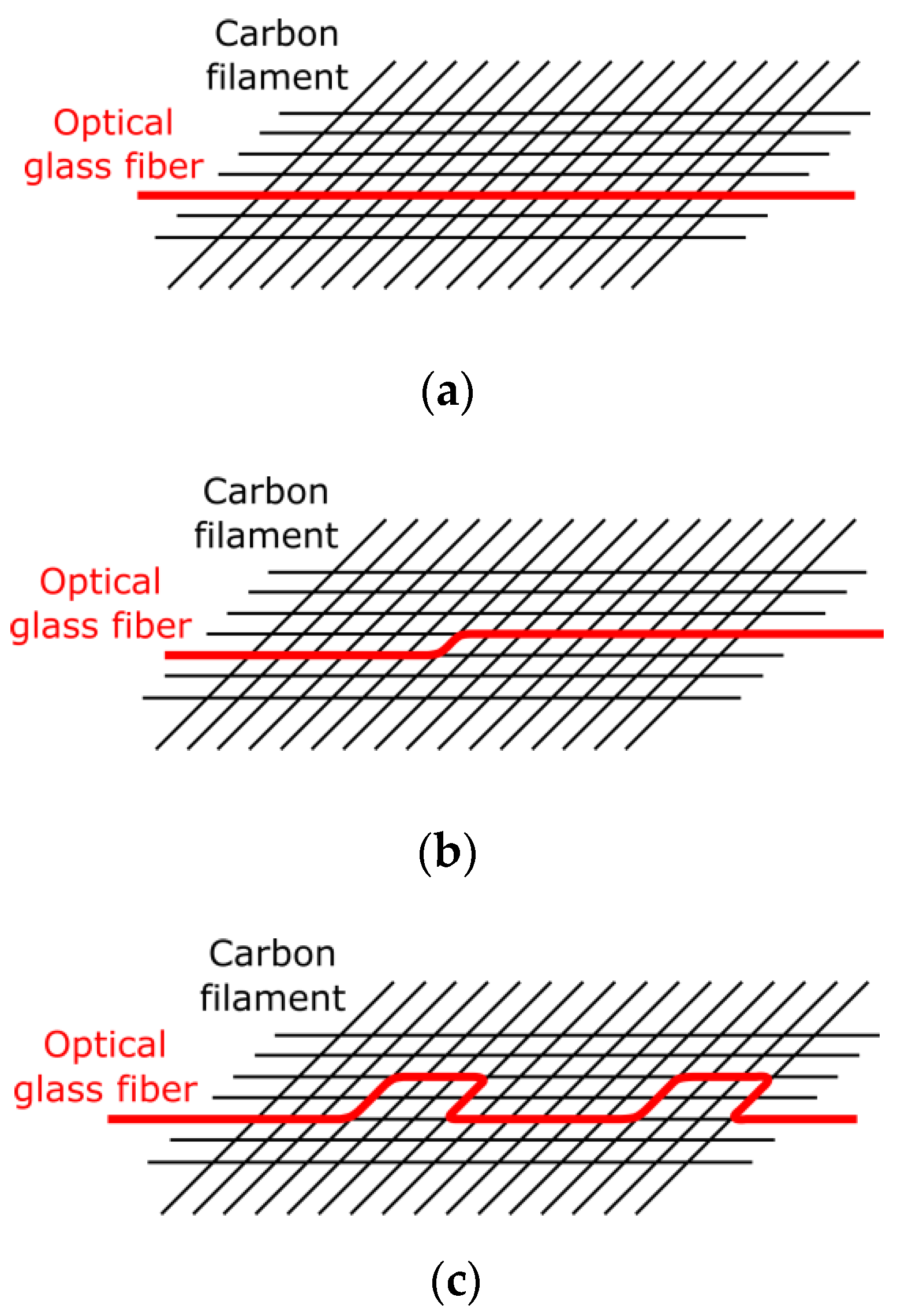
2.2. Optical Glass Fibers

Since FCSs are designed for reinforced concrete structures, the optical fibers inside FCSs have to withstand the highly alkaline concrete environment and still be fully capable of expected operations in terms of sensing and light guidance. Usually a fiber coating is applied in order to protect the optical silica glass fiber against impacts and thus to avoid mechanical degradation. However, when, for instance, the fiber is subjected to harsh environments, such as highly alkaline concrete environments, the fiber coating might be destroyed and thus the optical glass fiber might lose its mechanical stability. Therefore, commercially available optical fibers with different fiber coatings have been investigated in terms of their suitability to be applied for FCS applications. For the investigation, the Corning CC with acrylate coating (ClearCurve ZBL), the OFS Fitel Clearlite with polyimide (PI) (F21976) coating as well as the OFS GEOSIL with carbon/polyimide (C/PI) (BF06159) coating were chosen.

2.3. Evaluating Sensitivity to Micro- and Macro-Bending of Optical Fibers

In addition, an advantage of optical fibers applied for FCSs, discussed in Section 2.2, is that they can be processed during the embroidery fabrication process, i.e., any breaks while embroidering on the PVA nonwoven substrate can be avoided as well as the introduced light attenuation inside the optical glass fiber due to micro- and macro-bending can be neglected. Hence, in order to investigate their sensitivity to micro- and macro-bending when embroidered on the substrate, an experimental set-up was designed that consisted of a 3D printed mold and a power meter (dB-meter from FiboTec). The 3D printed mold enables the periodic and reproducible bending of the glass fiber with a bending radius of five millimeters and the power meter is used to monitor the introduced light attenuation inside the optical glass fiber. The minimum bending radius of 5 mm was determined from the fabrication process of the FCS. In Figure 3, a picture of the experimental setup consisting of the 3D printed mold and the power meter is illustrated.

2.4. Simulated Highly Alkaline Concrete Environment

Moreover, the impact of the highly alkaline concrete on the optical fiber was simulated using a 5% NaOH solution (pH 14) [24]. The failure stress of the optical fibers as well as the sensor response to the FCSs was determined using the tensile testing machine (MFC Sensortechnik T3000) after being exposed to the 5% NaOH solution.
The 5% NaOH solution was used to simulate the influence of concrete pore water on the glass fiber and on the fiber coating, respectively. In case of determining the failure stress of the optical glass fibers for each exposure time, the mean value from five fiber samples were calculated. Moreover, the length of the fiber samples under test was 385 mm for the Corning CC and 280 mm for the OFS Clearlite and OFS GEOSIL. The length of the acrylate coated fiber was different due to the fixation of this fiber to the tensile testing machine. However, the length of all fibers-under-test was kept equal. Prior to the tensile tests, all fiber samples were strained up to 1 N and to additionally visualize the fiber surface after exposure to the highly alkaline 5% NaOH solution, images of the fibers were taken using a scanning electron microscope (SEM) at the Saxon textile research institute (STFI). To determine the sensor response of the FCSs after being exposed to simulated concrete pore water, the 300 mm long 1D-FCS was immersed in the 5% NaOH solution for three months. After the exposure, the 1D-FCSs was dried for one day and then subsequently mounted on the tensile testing machine. The sensor response was measured using the experimental setup described in Section 2.5.

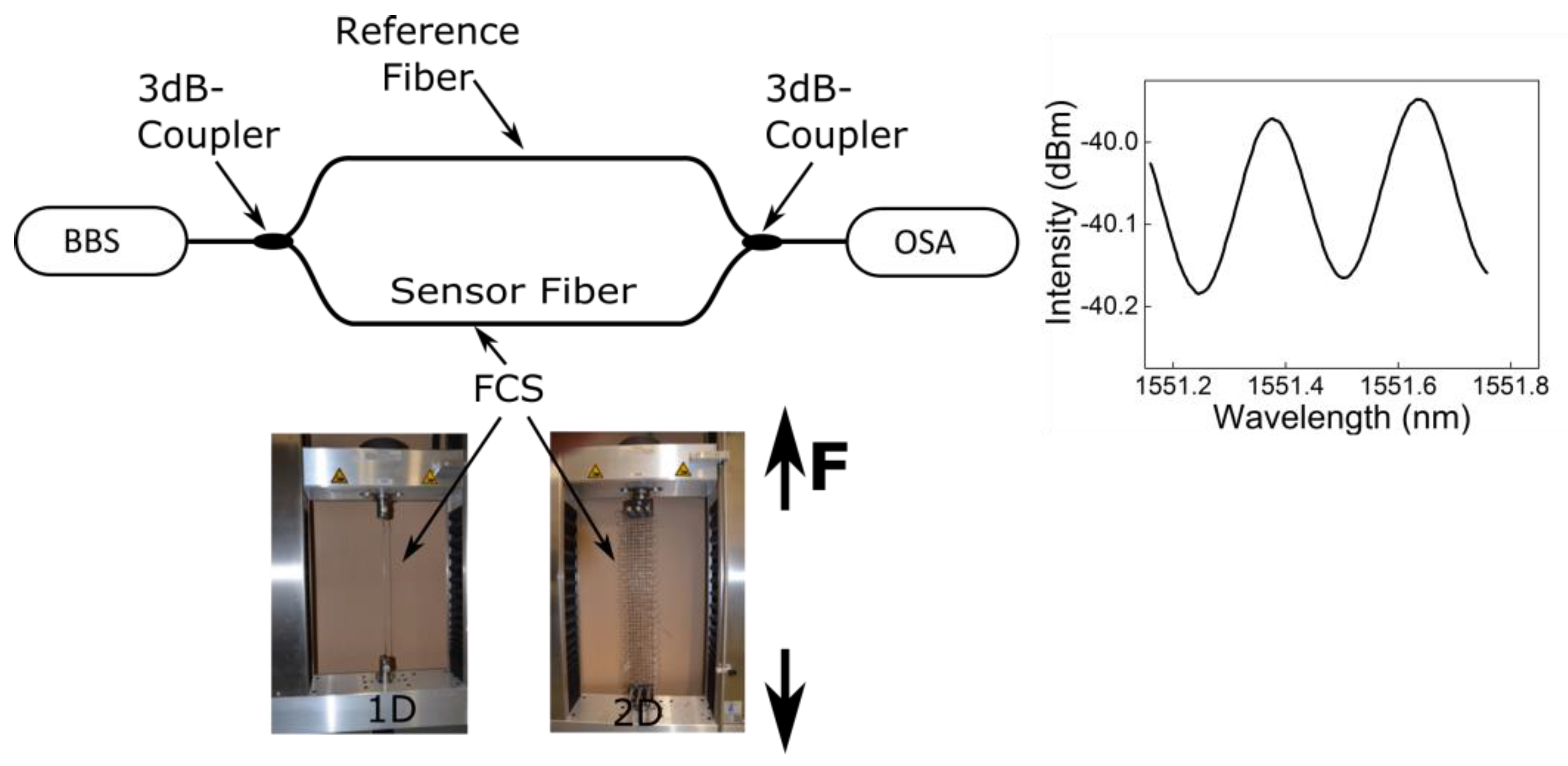
2.5. Evaluating Force Transfer of FCS

In order to investigate the sensor response of the FCS a fiber optic Mach-Zehnder (MZ) interferometer was applied [25]. The previously developed fiber optic MZ interferometer enables the investigation of the force transfer between the FCS and the optical glass fiber (fiber optic sensors) and thus the characterization of the bond between these two elements of the FCS. As illustrated in Figure 4, the applied fiber optic MZ interferometer consists of a broadband light source (BBS) (Opto-Link C-Band ASE), two fiber optic 3 dB couplers, two fiber arms, and a spectrometer (OSA) (Ando AQ6317B). The fiber optic MZ interferometer was set-up with only SM fiber components and all fiber components were spliced together. Moreover, the FCS was spliced to one arm of the developed interferometer in order to determine the strain transfer between the optical fiber and the FCS. When force is applied to the FCS using the tensile testing machine, the related length change of the optical fiber of the FCS causes a phase difference (Δφ) between the light (of wavelength λ) travelling in both fiber arms. This in turn results in a change of the interference pattern (displayed in the subset of Figure 4) from which the length change ΔL of the optical fiber inside the FCS can be determined as follows:
L = λ c 2 n c o r e · Δ λ
In Equation (1), n c o r e , λ c , and Δ λ are the refractive index of the fiber core, the central wavelength of the light source, and spectral difference between two adjacent maximums of the measured transmission spectrum of the Mach-Zehnder interferometer, respectively. The refractive index value for the fiber core was taken as 1.45.

3. Results

3.1. Response of Optical Fibers to Macro- and Micro-Bending

The results of the micro- and macro-bending tests of the optical glass fibers from Section 2.3 are summarized in Table 1. All three optical fibers show relatively less sensitivity to the applied bending. However, the best results were obtained for the two optical glass fibers from OFS (NA = 0.17). Therefore, due to less sensitivity to bending and thus the relatively low light attenuation, all three fiber types are suitable for the application in FCS.

3.2. Response of Optical Fibers to Simulated Alkaline Pore Water

The impact of the highly alkaline environment of the concrete on the optical glass fibers is summarized in Table 2 and Figure 5. The failure strain tests of the polyimide coated fiber had to be stopped after 14 days. This is due to the detachment of the polyimide coating from the glass fiber (Figure 5b). In addition, for the test on the polyimide coated fiber after been exposed to alkaline 5% NaOH solution, only three fiber samples could be measured, since all other fiber samples were already broken during mounting to the tensile testing machine. In case of the optical glass fiber with carbon coating, two different fabrication batches were evaluated. Fiber samples of the carbon coated optical glass fiber from the first fabrication batch were already consumed after 28 days of exposure to alkaline pore water. Therefore, a second batch of this fiber was ordered to at least conduct the resistant experiments to alkaline pore water over a period of one year. As can be seen in Table 2, the carbon coated optical glass fiber from the first fabrication batch did not show a clear trend towards a lower failure strain for increasing alkaline attack. However, in the case of the optical fibers with carbon coating from the second fabrication batch, a continuous degradation of the failure strain for increasing alkaline attack was observed. It is assumed that the defects in the coating from the second fabrication batch of the carbon coated optical glass fiber had allowed simulated pore water to attack the silica glass matrix of the fiber cladding. It can also be seen in Table 2 that the optical glass fiber with an acrylate coating shows continuous mechanical degradation with increasing alkaline attack.
Figure 5 shows different fiber coatings after being subjected to simulated alkaline attack. As can be clearly seen in Figure 5b, the polyimide coating is detached from the fiber after only 14 days of alkaline attack. No defects on the fiber coating could be detected for the optical glass fibers with acrylate (Figure 5a) and carbon (Figure 5c) coatings. The results obtained are consistent with [24,25], where acrylate and carbon coated fibers showed resistance against the highly alkaline environment.

3.3. Response of 1D-FCS to Simulated Alkaline Pore Water

The response of the FCS (equipped with Corning CC) to alkaline pore water was investigated using 400, 800, and 1600 tex 1D-FCSs. In Table 3, the sensitivity of 300 mm long FCSs to applied force are illustrated before and after exposure to the simulated alkaline pore water solution over a period of three months. For each tex number, three 1D-FCS samples were measured for increasing and decreasing force before and after the alkaline attack. In addition, before the measurements commenced, the 1D-FCS samples were strained prior to the measurement up to 5 N and the maximum applied strain was measured to be 6.7 mɛ during the tests. From Table 3, it follows that in general the FCSs are relatively stable against alkaline pore water attack. One reason for this might be the PVA that is used to stabilize the FCS and known to be relatively inert against chemicals. Furthermore, FCSs with higher tex numbers show less sensitivity to applied force (due to the increased cross-section) but in turn also less variation of the sensor response before and after the alkaline attack.

3.4. Sensor Response of FCS with Different Optical Fibre Configurations

In Figure 6, the sensor response of the FCSs with different optical fiber configurations are illustrated (for all three different fiber configurations the Corning CC was applied). Before the measurements were performed, the FCS samples were strained to a force of 40 N and the maximum applied strain was 2.4 mɛ during the tests. In case of configuration one (straight arrangement, Figure 6a) and two (offset arrangement, Figure 6b), a linear response to an applied force of 6.4 × 10⁻⁴ mm/N (R2 = 0.96) and 6.7 × 10⁻⁴ mm/N (R2 = 0.99), respectively, with a relatively low hysteresis of 4.4 × 10⁻⁵ mm/N and 1.9 × 10⁻⁵ mm/N, respectively, were obtained. In case of the third configuration (meander arrangement, Figure 6c), no correlation between the applied force and the length change of the optical fiber of the FCS could be observed (R2 = 0.25). The obtained result for configuration three suggests that due to the meander shape and thus due to the periodic spatial variation of the optical fiber inside the FCS, the bond between the optical fiber and the carbon filament is less strong (less bonding length) and thus the FCS is less sensitive to applied force. Therefore, the obtained results (from the three different fiber configurations) suggest that for sufficient sensor sensitivity, the bonding length between the optical fiber and the carbon filament to be at least ≥150 mm long (compare configuration two).

4. Conclusions

The results verified that all three different optical glass fibers can be applied for FCS applications. Following this, the resistance of the optical glass fibers to highly alkaline environment was evaluated where all three fiber coating materials showed degradation and thus not provide full protection against highly alkaline attack. However, optical glass fibers with carbon coating showed the most promising results. Carbon coated optical glass fibers of two different fabrication batches were evaluated. One fabrication batch showed almost no degradation due to alkaline attack while the failure strain of fibers of the second fabrication batch decreased with increasing exposure time to highly alkaline solution. Therefore, it is assumed that micro defects of the fiber coating of the second fabrication batch caused the degradation of the failure strain. The evaluation of the sensor response of the 1D-FCS before and after exposure to the NaOH solution indicated that the FCSs are relatively stable against alkaline pore water attack. One reason for this might be that the PVA that is used to stabilize the FCS is known to be relatively inert against chemicals. In addition, the response of the fiber optic sensors inside the FCS were investigated for three different fiber configurations. The purpose of the second and third configurations was to explore the spatial variation of the optical fiber inside the FCS and whether this results in a stronger bond between the optical glass fiber and FCS. The obtained results suggest that the bonding length between the optical fiber and the carbon filament should be at least ≥150 mm long in order to provide sufficient sensor sensitivity. Currently, work is ongoing to develop a theoretical model that will be used to simulate the work presented herewith, paving way to evaluate the optimum conditions for improved durability.

Author Contributions

Conceptualization, K.B., F.W., and B.R.; software, K.B. and M.K.; validation, K.B. and Y.Z., F.W. and M.K.; formal analysis, K.B., M.K., and F.W.; investigation, K.B., Y.Z., F.W., L.S.M.A., and M.K.; writing—original draft preparation, K.B. and L.S.M.A.; writing—review and editing, B.R.; supervision, B.R. and R.H.; project administration, B.R. and R.H.

Funding

This research was funded by the Bundesministerium fuer Bildung und Forschung (BMBF) within Grant Number 03ZZ0345 (Carbon Concrete Composite (C3)). B.R. acknowledges support by the Deutsche Forschungsgemeinschaft (DFG, German Research Foundation) under Germany’s Excellence Strategy within the Cluster of Excellence PhoenixD (EXC 2122). The publication of this article was funded by the Open Access fund of Leibniz Universität Hannover.

Conflicts of Interest

The authors declare no conflict of interest.

References

  1. Kouroussis, G.; Caucheteur, C.; Kinet, D.; Alexandrou, G.; Verlinden, O.; Moeyaert, V. Review of trackside monitoring solutions: From strain gages to optical fiber sensors. Sensors 2015, 15, 20115–20139. [Google Scholar] [CrossRef] [PubMed]
  2. Vardanega, P.J.; Webb, G.T.; Fidler, P.R.A.; Middleton, C.R. Innovative Bridge Design Handbook: Construction, Rehabilitation and Maintenance; Elsevier Inc.: Amsterdam, The Netherlands, 2015; pp. 759–775. [Google Scholar]
  3. Mihailov, S.J. Fiber Bragg grating sensors for harsh environments. Sensors 2012, 12, 1898–1918. [Google Scholar] [CrossRef] [PubMed]
  4. Pal, A.; Dhar, A.; Ghosh, A.; Sen, R.; Hooda, B.; Rastogi, V.; Ams, M.; Fabian, M.; Sun, T.; Grattan, K.T.V. Sensors for Harsh Environment: Radiation Resistant FBG Sensor System. J. Lightwave Technol. 2016, 35, 3393–3398. [Google Scholar] [CrossRef]
  5. Berruti, G.; Consales, M.; Giordano, M.; Sansone, L.; Petagna, P.; Buontempo, S.; Breglio, G.; Cusano, A. Radiation hard humidity sensors for high energy physics applications using polyimide-coated fiber Bragg gratings sensors. Sens. Actuators B Chem. 2013, 177, 94–102. [Google Scholar] [CrossRef]
  6. Hassan, M.R.A.; Bakar, M.H.A.; Dambul, K.; Adikan, F.R.M. Optical-based sensors for monitoring corrosion of reinforcement rebar via an etched cladding Bragg grating. Sensors 2012, 12, 15820–15826. [Google Scholar] [CrossRef]
  7. Alwis, L.S.M.; Bustamante, H.; Bremer, K.; Roth, B.; Sun, T.; Grattan, K.T.V. Evaluation of the durability and performance of FBG-based sensors for monitoring moisture in an aggressive gaseous waste sewer environment. J. Lightwave Technol. 2017, 35, 3380–3386. [Google Scholar] [CrossRef]
  8. Bremer, K.; Meinhardt-Wollweber, M.; Thiel, T.; Werner, G.; Sun, T.; Grattan, K.T.V.; Roth, B. Sewerage tunnel leakage detection using a fiber optic moisture-detecting sensor system. Sens. Actuators A Phys. 2014, 220, 62–68. [Google Scholar] [CrossRef]
  9. Bremer, K.; Weigand, F.; Kuhne, M.; Wollweber, M.; Helbig, R.; Rahlves, M.; Roth, B. Fiber optic sensor systems for the structural health monitoring of building structures. Procedia Technol. 2016, 26, 524–529. [Google Scholar] [CrossRef]
  10. Thevenaz, L.; Facchini, M.; Fellay, A.; Robert, P.; Inaudi, D.; Dardel, B. Monitoring of large structures using distributed Brillouin fiber sensing. SPIE Proc. 1999, 3746, 345–348. [Google Scholar]
  11. Measures, R.M.; Alavie, A.T.; Maaskant, R.; Ohn, M.M.; Karr, S.E.; Huang, S.Y. Bragg grating structural sensing system for bridge monitoring. SPIE Proc. 1994, 2294, 53–60. [Google Scholar]
  12. Ansari, F. Practical Implementation of Optical Fiber Sensors in Civil Structural Health Monitoring. J. Intell. Mater. Syst. Struct. 2007, 18, 879–889. [Google Scholar] [CrossRef]
  13. Khan, S.; Ali, S.; Bermak, A. Recent Developments in Printing Flexible and Wearable Sensing Electronics for Healthcare Applications. Sensors 2019, 19, 1230. [Google Scholar] [CrossRef] [PubMed]
  14. Han, T.; Kundu, S.; Nag, A.; Xu, Y. 3D Printed Sensors for Biomedical Applications: A Review. Sensors 2019, 19, 1706. [Google Scholar] [CrossRef] [PubMed]
  15. Chen, X.; An, J.; Cai, G.; Zhang, J.; Chen, W.; Dong, X.; Zhu, L.; Tang, B.; Wang, J.; Wang, X. Environmentally Friendly Flexible Strain Sensor from Waste Cotton Fabrics and Natural Rubber Latex. Sensors 2019, 11, 404. [Google Scholar] [CrossRef]
  16. Wu, L.; Maheshwari, M.; Yang, Y.; Xiao, W. Selection and Characterization of Packaged FBG Sensors for Offshore Applications. Sensors 2018, 18, 3963. [Google Scholar] [CrossRef] [PubMed]
  17. Luyckx, G.; Voet, E.; Lammens, N.; Degrieck, J. Strain measurements of composite laminates with embedded fiber Bragg gratings: Criticism and opportunities for research. Sensors 2011, 11, 384–408. [Google Scholar] [CrossRef] [PubMed]
  18. Barrias, A.; Casas, J.R.; Villalba, S. A review of distributed optical fiber sensors for civil engineering applications. Sensors 2016, 16, 748. [Google Scholar] [CrossRef] [PubMed]
  19. Scheerer, S.; Schütze, E.; Curbach, M. Strengthening and Repair with Carbon Concrete Composites—The First General Building Approval in Germany. In Proceedings of the International Conference on Strain-Hardening Cement-Based Composites (SHCC 2017), Dresden, Germany, 18–20 September 2018. [Google Scholar]
  20. Wiederhorn, S.M.; Johnson, H. Effect of electrolyte pH on crack propagation in glass. J. Am. Ceram. Soc. 1973, 56, 192–197. [Google Scholar] [CrossRef]
  21. Mendez, A.; Morse, T.F.; Mendez, F. Applications of Embedded Optical Fiber Sensors in Reinforced Concrete Buildings and Structures. SPIE Proc. 1990, 1170, 60–70. [Google Scholar]
  22. Ansari, F. State-of-the-art in the Applications of Fiber-optic Sensors to Cementitious Composites. Cem. Concr. Compos. 1997, 19, 3–19. [Google Scholar] [CrossRef]
  23. Kuwabara, T.; Katsuyama, Y. Polyetherimide Coated Optical Silica Glass Fiber with High Resistance to Alkaline Solution. In Optical Fiber Communication Conference; Vol. 5 of 1989 OSA Technical Digest Series; Optical Society of America: Washington, DC, USA, 1989; p. WA4. [Google Scholar]
  24. Habel, W.R.; Hopcke, M.; Basedau, R.; Polster, H. The influence of concrete and alkaline solutions on different surfaces of optical fibers for sensors. In Proceedings of the 2nd European Conference on Smart Structures and Materials, Glasgow, UK, 12–14 October 1994; pp. 168–171. [Google Scholar]
  25. Habel, W.R.; Hofmann, D.; Hillemeier, B. Deformation measurements of mortars at early ages and of large concrete components on site by means of embedded fiber-optic microstrain sensors. Cem. Concr. Compos. 1997, 19, 81–102. [Google Scholar] [CrossRef]
  26. Bremer, K.; Weigand, F.; Zheng, Y.; Alwis, L.S.; Helbig, R.; Roth, B. Structural Health Monitoring Using Textile Reinforcement Structures with Integrated Optical Fiber Sensors. Sensors 2017, 17, 345. [Google Scholar] [CrossRef] [PubMed]
  27. Bremer, K.; Alwis, L.S.; Weigand, F.; Kuhne, M.; Zheng, Y.; Krüger, M.; Helbig, R.; Roth, B. Evaluating the Performance of Functionalized Carbon Structures with Integrated Optical Fiber Sensors under Practical Conditions. Sensors 2018, 18, 3923. [Google Scholar] [CrossRef] [PubMed]
Figure 1. Schematic of the application of functionalized carbon structures (FCS) for the reinforcement and structural health monitoring (SHM) of concrete structures.
Applsci 09 02476 g001
Figure 2. 2D-FCSs with different optical fiber sensor configurations. Straight (a), with an offset (b) and meander (c) fiber configurations were applied to investigate the bond between optical fiber and the carbon filament.
Applsci 09 02476 g002
Figure 3. Experimental setup to evaluate the sensitivity to micro- and macro-bending effects on the applied optical glass fibers.
Applsci 09 02476 g003
Figure 4. Fiber optic Mach-Zehnder (MZ) interferometer to characterize the sensor response from the FCS under test.
Applsci 09 02476 g004
Figure 5. Scanning electron microscope (SEM) images of the optical glass fiber with acrylate (a), polyimide (b), and carbon/polyimide (c) coatings after 14- and 28-days of alkaline attack, respectively.
Applsci 09 02476 g005
Figure 6. Sensor response for the 2D-FCSs with straight (bonding length 300 mm) (a), offset (bonding length 150 mm) (b), and meander (bonding length 60 mm) (c) optical fiber configurations.
Applsci 09 02476 g006
Table 1. Results of the micro- and macro-bending test of the optical glass fibers with different protective coatings. CC: ClearCurve; PI: Polyimide; C/PI: Carbon/Polyimide.
Fiber-Type10 turns [dB]20 turns [dB]30 turns [dB]40 turns [dB]
Corning CC−0.06−0.11−0.2−0.28
OFS PI0000
OFS C/PI00−0.10
Table 2. Change of the mean failure strain of the optical glass fibers with different fiber coating for different exposure times to highly alkaline 5% NaOH solution. N specifies the number of samples per test.
AcrylatePolyimideCarbon/Polyimide
(Batch #1)
Carbon/Polyimide
(Batch #2)
Before exposure1.27 GPa
N = 5
3.29 GPa
N = 5
2.29 GPa
N = 5
2.10 GPa
N = 5
After exposure0.90 GP
(14 days)
N = 5
0.59 GPa
(14 days)
N = 3
2.20 GPa
(14 days)
N = 5
1.94 GPa
(14 days)
N = 5
0.83 GPa
(3 months)
N = 5
2.23 GPa
(28 days)
N = 5
0.91 GPa
(30 days)
N = 5
0.34 GPa
(1 year)
N = 5
Table 3. Change of the sensor response from 1D-FCS due to exposure times to highly alkaline 5% NaOH solution. σ specifies the standard deviation of the measurement.
400 Tex Filament800 Tex Filament1600 Tex Filament
Before exposure0.0093 mm/N
(σ = 3.5 × 10⁻⁴)
0.0065 mm/N
(σ = 2.1 × 10⁻⁴)
0.0018 mm/N
(σ = 1.1 × 10⁻⁴)
After exposure0.0174 mm/N
(σ = 7.3 × 10⁻⁴)
0.0077 mm/N
(σ = 4.1 ×10⁻⁴)
0.0023 mm/N
(σ = 1.7 × 10⁻⁴)

