Abstract
In the present paper, the fatigue life assessment of notched structural components is performed by applying a critical plane-based multiaxial fatigue criterion. Such a criterion is formulated by using the control volume concept related to the strain energy density criterion. The verification point is assumed to be at a given distance from the notch tip. Such a distance is taken as a function of the control volume radii around the notch tip under both Mode I and Mode III loading. The accuracy of the present criterion is evaluated through experimental data available in the literature, concerning titanium alloy notched specimens under uniaxial and multiaxial fatigue loading.
1. Introduction
From the pioneering work by Jasper at the beginning of the 1920s [1], energy-based criteria have been widely used for estimating multiaxial fatigue lifetime of engineering components subjected to time-varying loading [2,3,4,5,6,7,8,9,10]. The fundamental idea on which such criteria are based is the assumption that energy (calculated in different ways) is always proportional to fatigue damage.
Among the different energy-based criteria available in the literature [2], those proposed by Garud [3] and Ellyin et al. [4,5,6] are very interesting. The multiaxial fatigue assessment has to be performed through the cyclic plastic deformation according to Garud, whereas Ellyin et al. argued that both cyclic plastic energy and elastic energy have to be properly taken into account in the fatigue lifetime estimation.
It is worth noting that the fatigue life of notched structural components subjected to cyclic loading can be evaluated by means of energy-based concepts. In particular, the concept of strain energy density (SED) has originally been implemented in different criteria available in the literature to predict the fatigue behavior of notched components under uniaxial tensile loading [7,8]. Subsequently, SED-based criteria have been formulated for multiaxial loading [9,10].
The main drawback of the above criteria is that the fatigue behavior is assumed to depend only on the stresses at the notch tip. Therefore, any SED-based criterion cannot be applied at the tip of sharp notches since both the stress state and SED tend toward infinite.
In order to overcome the above problem, Lazzarin and Zambardi suggested considering a small but finite volume of material close to the notch tip (that is, the point of stress singularity), over which the SED has a finite value [11]. More precisely, the fatigue damage parameter for blunt and sharp notched structural components under tensile loading (Mode I) is the mean value of the SED, related to a control volume around the notch tip [11,12]. The radius of the above volume depends on the unnotched specimen fatigue limit, the notch stress intensity factor (NSIF) range and the elastic Poisson’s ratio. The Lazzarin and Zambardi criterion has also been extended to notched structural components subjected to multiaxial loading [13,14,15,16,17,18] as well as to welded joints [19,20,21].
Recently, an attempt to perform the fatigue lifetime assessment of notched specimens through energy concepts has been made by Carpinteri and co-workers [22,23,24], relatively to Ti–6Al–4V titanium alloy specimens under uniaxial and multiaxial loading (biaxiality ratio 0.6 and 2.0), where the control volume concept has been implemented in the original formulation of the critical plane-based multiaxial fatigue criterion [25,26].
In the present paper, the above criterion is proposed to be applied together with the control volume concept, and fatigue assessment is performed in a verification point at a distance related to energy concepts.
It is validated by means of experimental data related to V-notched specimens made of titanium grade 5 alloy, subjected to mixed mode loading [27]. Such material and other titanium alloys have attracted significant interest being extensively used in leading industries, due to their low density and high specific strength at elevated temperature (aeronautics, nuclear energy) and their compatibility with human tissues (applications in the biomedical field) [28,29,30,31,32]. In the latter field, such materials can be used, for example, in the form of β-type titanium porous structures [30,31], and functionally graded Ti-6Al-4V alloy interconnected mesh structures [32].
In Section 2, the theoretical framework of the strain-based criterion by Carpinteri et al. is outlined, also implementing the concept of control volume [22,23,24]. Then, the validation of such a criterion by means of experimental data for combined tension and torsion cyclic loading on V-notched specimens is shown in Section 3, and finally, the conclusions are drawn in Section 4.
2. Theoretical Framework of Strain-Based Multiaxial Fatigue Criterion
The strain-based multiaxial fatigue criterion by Carpinteri et al. [25,26] is related to the critical plane approach and consists of three steps detailed in the following sub-sections: Step I, where the verification point position (point ) is analytically defined by means of the control volume concept, Step II, where the critical plane orientation is theoretically determined, Step III, where the fatigue life assessment is performed in such a plane at point . The criterion is suitable to be applied to ductile materials under low cycle fatigue loading.
2.1. Step I: Verification Point Position
The fatigue lifetime is computed at point which is on the notch bisector at a certain distance, , from the notch surface [25,26] (Figure 1). The expression of the above distance is obtained by means of a best fitting procedure (details are provided in Reference [24]) and is given by [22]:
where is the ratio between the amplitude of the remote shear stress and the amplitude of the remote normal stress (named biaxiality ratio) and is computed as the mean value of (control volume radius under Mode I loading) and (control volume radius under Mode III loading). The last ones are calculated by the SED criterion, and are functions of notch stress intensity factor (NSIF) ranges (, ), high-cycle fatigue strengths of smooth specimens (, ) and the notch geometry [33]. More precisely, the above radii are computed according to the following equations [33]:
where and are two parameters depending on the V-notch geometry, is the elastic Poisson ratio, and and are the eigenvalues for Mode I and Mode III, respectively, calculated by means of finite element analysis, as is discussed in Reference [33].
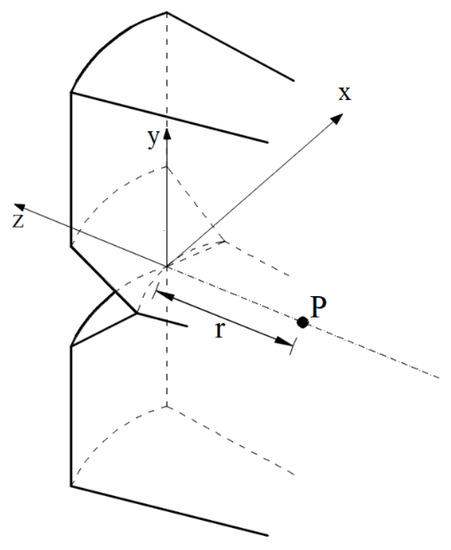
Figure 1.
Verification point position according to the control volume concept for V-notch.
A finite element model is employed in order to numerically compute the strain state at verification point [24]. In particular, linear transient dynamic analyses are performed on notched specimens through the Commercial Package Straus7® [34], by adopting both 6- and 8-node tridimensional finite elements. Only one half of each specimen is modeled, taking advantage of the geometric symmetry. Moreover, the adopted discretization is shown in Figure 2, where the finite element mesh is that adopted after a convergence analysis, being the minimum finite element size equal to about 0.25 times the value of the notch root radius.
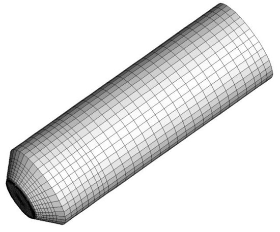
Figure 2.
Discretization adopted for the finite element model.
2.2. Step II: Critical Plane Orientation
Let us consider the strain state at point and a generic time instant of the fatigue loading history, the principal strain , and (with ) and the corresponding directions , and (identified by means of the principal Euler angles , and ) can be determined. Since the principal directions are usually time-varying under fatigue loading, Carpinteri et al. proposed to compute the averaged directions and on the basis of the instantaneous ones, through the averaged values of the principal Euler angles [35].
Then, the critical plane orientation is regarded to depend on such averaged directions. In more detail, the normal vector to the critical plane is assumed to be linked to the -direction through an off-angle , given by the following empirical expression [25,26]:
being the effective Poisson ratio (that is, function of both elastic, , and plastic, , Poisson’s ratio), and and the strain amplitudes in the well-known tensile and torsional Manson–Coffin equations, respectively. Note that the above rotation (Equation (2)) has to be performed from to in the principal plane .
2.3. Step III: Fatigue Life Assessment
The fatigue life assessment is performed through the following expression, where the left-hand term corresponds to an equivalent strain whose amplitude is a function of the amplitudes and of both the normal and the tangential displacement vectors [25,26]:
Note that all terms in Equation (3) depend on the number of loading cycles to failure. Moreover, the values of and are obtained from an analytical procedure by taking into account both the strain tensor at point and the critical plane orientation. Details can be found in Reference [24].
The fatigue life (i.e. the theoretical number of loading cycles to failure, ) is iteratively computed by equaling Equation (4) [24] with the Manson–Coffin normal strain amplitude .
3. Criterion Validation
In order to check the accuracy of the criterion presented in Section 2, some experimental data are selected from the technical literature [27,33]. Such data are related to uniaxial and multiaxial fatigue tests (with nominal loading ratio equal to ) carried out on circumferentially V-notched cylindrical specimens characterized by (Figure 3):
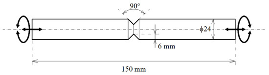
Figure 3.
Geometrical sizes of the titanium alloy V-notched specimens subjected to tension and/or torsion fatigue loading.
- V-notch with a depth of mm;
- Opening angle of ;
- Notch root radius of mm.
The above specimens were made of grade 5 titanium alloy (Ti-6Al-4V), commonly used in aerospace and naval applications. The above titanium alloy is characterized by very good static and fatigue properties (Table 1) with a high strength-to-mass ratio.

Table 1.
Static and fatigue properties of material examined [27,33].
The Manson–Coffin parameters of both tensile and torsional equations are reported in Reference [22].
By taking full advantage of , , , and , the control volume radii and are equal to mm and mm, respectively.
Before being fatigue tested, the specimens have been polished in order to remove surface scratches and marks due to machine tools. Fatigue tests have been performed by means of an MTS 809 servo-hydraulic axial-torsional testing system with a 100 kN axial cell and a 1100 Nm torsion cell. Moreover, all tests have been carried out under load control, with a frequency between 10 and 15 Hz. Details of the loading conditions related to the experimental fatigue tests being examined are reported in Reference [27,33]. In particular, we consider four different loading conditions characterized by experimental fatigue life, , between and loading cycles, and more precisely:
- Pure tension fatigue loading;
- Pure torsion fatigue loading;
- Combined in-phase () tension and torsion fatigue loading;
- Combined out-of-phase () tension and torsion fatigue loading.
The biaxiality ratio related to multiaxial loading conditions is equal to .
According to the above loading conditions, the value of the distance (Equation (1)) turns out to be:
- (a)
- for pure tension fatigue loading ();
- (b)
- for pure torsion fatigue loading ();
- (c)
- for combined tension and torsion fatigue loading ().
Figure 4 shows experimental fatigue life, , plotted against the theoretical one, . In particular, of results is conservative and is included into × band. Moreover, we can remark that better estimations are obtained by considering only the in-phase multiaxial fatigue data (Figure 4b) since all the results fall within × band, whereas almost all the results related to out-of-phase data are outside the above band (Figure 4c).
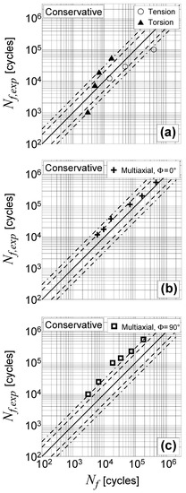
Figure 4.
Accuracy of the present criterion in estimating the fatigue lifetime of Ti-6Al-4V notched specimens: (a) Uniaxial loading, (b) multiaxial proportional loading, (c) multiaxial non-proportional loading.
In any case, when estimations do not fall within the reference bands, the errors made by the present criterion are, in general, on the conservative side. This strongly supports the idea that the Carpinteri et al. criterion, applied together with the control volume concept, can be used successfully to assess notched components in situations of practical interest, always allowing an adequate margin of safety to be reached.
Figure 5 shows as a function of the equivalent strain amplitude, (see Equation (4)). Note that the solid line is the experimental tensile Manson–Coffin equation. Since all the theoretical data lie very close to the experimental curve, it can be concluded that the accuracy level of the employed criterion is satisfactory.
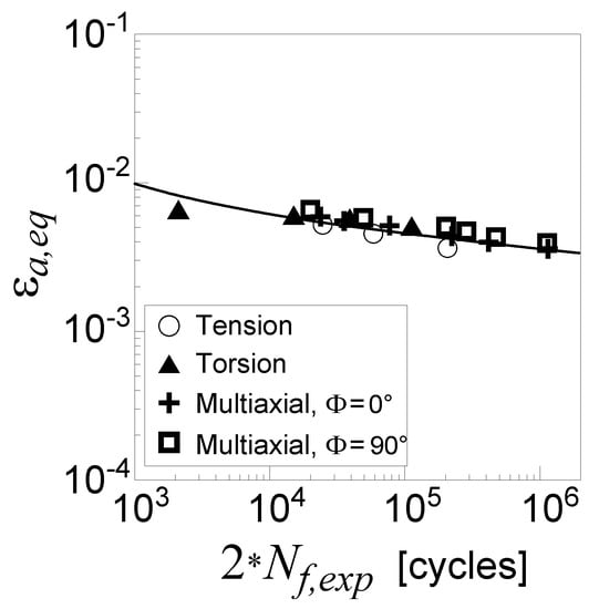
Figure 5.
Experimental fatigue life against equivalent strain amplitude .
The above considerations can also be made by examining the values of the error index, , computed as follows [24]:
In particular, Figure 6 shows the relative frequency of the absolute value. It can be observed that the frequency distribution is close to zero, with of the results in the range .
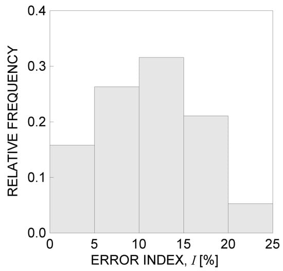
Figure 6.
Absolute value of the error index according to the present criterion.
In conclusion, we can remark that the implementation of energy concepts, based on the control volume, in the above strain-based multiaxial fatigue criterion appears an interesting tool for evaluating the fatigue behavior of severely notched components.
4. Conclusions
In the present paper, the fatigue life assessment of notched structural components has been performed by applying a critical plane-based multiaxial fatigue criterion. Such a criterion has been formulated by using the control volume concept related to the strain energy density criterion.
The material point located at a given distance from the notch tip is assumed to be the verification point. Such a distance has been taken to be a function of the control volume radii around the notch tip under both Mode I and Mode III loading. Once the position of the verification point and the orientation of the critical plane have been analytically determined, the fatigue lifetime has theoretically been evaluated through an equivalent normal strain amplitude, acting on the critical plane, together with the tensile Manson–Coffin curve.
The accuracy of the present criterion is evaluated through experimental data available in the literature, related to titanium alloy V-notched specimens under uniaxial and multiaxial fatigue loading. As far as the experimental data here examined are concerned, the joint application of the strain-based criterion and the control volume concept provides quite satisfactory fatigue life estimations.
On the basis of the encouraging results herein obtained, the present criterion seems to be able to correctly estimate the fatigue life of a structure with a stress concentrator (as a notch), by reaching an adequate margin of safety. However, different materials, notch geometries, and loading conditions need to be examined in order to develop a useful fatigue design tool.
Author Contributions
Conceptualization, A.C., C.R. and S.V.; methodology, A.C. and S.V.; validation, C.R. and S.V.; formal analysis, C.R.; writing—original draft preparation, C.R. and S.V.; writing—review and editing, A.C.; funding acquisition, A.C. and S.V.
Funding
This research was founded by the Italian Ministry for University and Technological and Scientific Research (MIUR), Research Grant PRIN 2015 No. 2015JW9NJT on ‘‘Advanced mechanical modeling of new materials and structures for the solution of 2020 Horizon challenges”.
Acknowledgments
The authors gratefully acknowledge the financial support provided by the Italian Ministry for University and Technological and Scientific Research (MIUR), Research Grant PRIN 2015 No. 2015JW9NJT on “Advanced mechanical modeling of new materials and structures for the solution of 2020 Horizon challenges”.
Conflicts of Interest
The authors declare no conflict of interest.
Nomenclature
| principal strain directions | |
| averaged principal strain directions | |
| elastic modulus | |
| error index | |
| theoretical fatigue life | |
| experimental fatigue life | |
| verification point | |
| distance of the verification point from the notch tip | |
| mean control volume radius | |
| control volume radius related to Mode I | |
| control volume radius related to Mode III | |
| time | |
| perpendicular unit vector to the critical plane | |
| Manson–Coffin shear strain amplitude | |
| angle between the averaged direction and the normal to the critical plane | |
| notch stress intensity factor range under Mode I | |
| notch stress intensity factor range under Mode III | |
| high-cycle fatigue strength of smooth specimens under Mode I | |
| high-cycle Fatigue strength of smooth specimens under Mode III | |
| principal strains, with | |
| Manson–Coffin normal strain amplitude | |
| equivalent normal strain amplitude | |
| amplitude of the normal displacement vector component acting on the critical plane | |
| amplitude of the tangential displacement vector component acting on the critical plane | |
| biaxiality ratio | |
| elastic Poisson ratio | |
| effective Poisson ratio | |
| plastic Poisson ratio | |
| ultimate tensile strength | |
| yield strength | |
| phase angle between tension and torsion loading |
References
- Jasper, T.M. The value of the energy relation in the testing of ferrous metals at varying ranges of stress and at intermediate and high temperatures. Philos. Mag. Ser. 1923, 6, 609–627. [Google Scholar] [CrossRef]
- Macha, E.; Sonsino, C.M. Energy criteria of multiaxial fatigue failure. Fatigue Fract. Eng. Mater. Struct. 1999, 22, 1053–1070. [Google Scholar] [CrossRef]
- Garud, Y.S. A new approach to the evaluation of fatigue under multiaxial loadings. J. Eng. Mater. Technol. 1981, 103, 118–125. [Google Scholar] [CrossRef]
- Ellyin, F. Cyclic strain energy density as a criterion for multiaxial fatigue failure. In Biaxial and Multiaxial Fatigue; EGF, 3, Carpinteri, A., De Freitas, M., Spagnoli, A., Eds.; Mechanical Engineering: London, UK, 1989; pp. 571–583. [Google Scholar]
- Ellyin, F.; Golos, K.; Xia, Z. In-phase and out-of-phase multiaxial fatigue. J. Eng. Mater. Technol. 1991, 113, 112–118. [Google Scholar] [CrossRef]
- Ellyin, F.; Xia, Z. A general fatigue theory and its application to out-of-phase cyclic loading. J. Eng. Mater. Technol. 1993, 115, 411–416. [Google Scholar] [CrossRef]
- Molsky, K.; Glinka, G. A method of elastic-plastic stress and strain calculation at a notch root. Mater. Sci. Eng. 1981, 50, 93–100. [Google Scholar] [CrossRef]
- Glinka, G. Energy density approach to calculation of inelastic strain-stress near notches and cracks. Eng. Fract. Mech. 1985, 22, 485–508. [Google Scholar] [CrossRef]
- Moftakhar, A.; Buczynski, A.; Glinka, G. Calculation of elasto-plastic strains and stresses in notches under multiaxial loading. Int. J Fracture 1995, 70, 357–373. [Google Scholar] [CrossRef]
- Park, J.; Nelson, D. Evaluation of an energy-based approach and a critical plane approach for predicting constant amplitude multiaxial fatigue life. Int. J. Fatigue 2000, 22, 23–39. [Google Scholar] [CrossRef]
- Lazzarin, P.; Zambardi, R. A finite-volume-energy based approach to predict the static and fatigue behavior of components with sharp V-shaped notches. Int. J. Fract. 2001, 112, 275–298. [Google Scholar] [CrossRef]
- Lazzarin, P.; Berto, F. Some expressions for the strain energy in a finite volume surrounding the root of blunt V-notches. Int. J. Fract. 2005, 135, 161–185. [Google Scholar] [CrossRef]
- Atzori, B.; Berto, F.; Lazzarin, P.; Quaresimin, M. Multi-axial fatigue behaviour of a severely notched carbon steel. Int. J. Fatigue 2006, 28, 485–493. [Google Scholar] [CrossRef]
- Berto, F.; Lazzarin, P.; Tovo, R. Multiaxial fatigue strength of severely notched cast iron specimens. Int. J. Fatigue 2014, 67, 15–27. [Google Scholar] [CrossRef]
- Meneghetti, G.; Campagnolo, A.; Berto, F.; Atzori, B. Averaged strain energy density evaluated rapidly from the singular peak stresses by FEM: cracked components under mixed-mode (I+II) loading. Theor. Appl. Fract. Mech. 2015, 79, 113–124. [Google Scholar] [CrossRef]
- Ayatollahi, M.R.; Berto, F.; Campagnolo, A.; Gallo, P.; Tang, K. Review of local strain energy density theory for the fracture assessment of V-notches under mixed mode loading. Eng. Solid Mech. 2017, 5, 113–132. [Google Scholar] [CrossRef]
- Berto, F.; Ayatollahi, M.R.; Campagnolo, A. Fracture tests under mixed mode I + III loading: An assessment based on the local energy. Int. J. Damage Mech. 2017, 26, 881–894. [Google Scholar] [CrossRef]
- Torabi, A.R.; Berto, F.; Razavi, S.M.J. Ductile failure prediction of thin notched aluminum plates subjected to combined tension-shear loading. Theor. Appl. Fract. Mech. 2018, 97, 280–288. [Google Scholar] [CrossRef]
- Lazzarin, P.; Berto, F.; Atzori, B. A synthesis of data from steel spot welded joints of reduced thickness by means of local SED. Theor. Appl. Fract. Mech. 2013, 63–64, 32–39. [Google Scholar] [CrossRef]
- Chebat, F.; Peron, M.; Viespoli, L.M.; Welo, T.; Berto, F. Fatigue strength assessment of steel rollers: on the reliability of the strain energy density approach on real components. Appl. Sci. 2018, 8, 1015. [Google Scholar] [CrossRef]
- Viespoli, L.M.; Berto, F.; Somà, A. Fatigue life assessment for a welded detail: Advantages of a local energetic approach and experimental validation. Frattura ed Integrità Strutturale 2018, 12, 121–134. [Google Scholar] [CrossRef]
- Carpinteri, A.; Berto, F.; Campagnolo, A.; Fortese, G.; Ronchei, C.; Scorza, D.; Vantadori, S. Fatigue assessment of notched specimens by means of a critical plane-based criterion and energy concepts. Theor. Appl. Fract. Mech. 2016, 84, 57–63. [Google Scholar] [CrossRef]
- Carpinteri, A.; Fortese, G.; Ronchei, C.; Scorza, D.; Vantadori, S.; Berto, F. Joined application of a multiaxial critical plane criterion and a strain energy density criterion in low-cycle fatigue. Fract. Struct. Integr. 2017, 11, 66–70. [Google Scholar] [CrossRef]
- Vantadori, S.; Carpinteri, A.; Fortese, G.; Ronchei, C.; Scorza, D.; Zanichelli, A. Fatigue lifetime evaluation of notched components: implementation of the control volume concept in a strain-based LCF criterion. Theor. Appl. Fract. Mech. 2018, 97, 400–408. [Google Scholar] [CrossRef]
- Carpinteri, A.; Ronchei, C.; Spagnoli, A.; Vantadori, S. Lifetime estimation in the low/medium-cycle regime using the Carpinteri–Spagnoli multiaxial fatigue criterion. Theor. Appl. Fract. Mech. 2014, 73, 120–127. [Google Scholar] [CrossRef]
- Carpinteri, A.; Ronchei, C.; Scorza, D.; Vantadori, S. Fatigue life estimation for multiaxial low-cycle fatigue regime: The influence of the effective Poisson ratio value. Theor. Appl. Fract. Mech. 2015, 79, 77–83. [Google Scholar] [CrossRef]
- Berto, F.; Campagnolo, A.; Welo, T. Local strain energy density to assess the multiaxial fatigue strength of titanium alloys. Fract. Struct. Integr. 2016, 10, 69–79. [Google Scholar] [CrossRef]
- Attar, H.; Calin, M.; Zhang, L.C.; Scudino, S.; Eckert, J. Manufacture by selective laser melting and mechanical behavior of commercially pure titanium. Mater. Sci. Eng. A 2014, 593, 170–177. [Google Scholar] [CrossRef]
- Ehtemam Haghighi, S.; Lu, H.B.; Jian, G.Y.; Cao, G.H.; Habibi, D.; Zhang, L.C. Effect of α″ martensite on the microstructure and mechanical properties of beta-type Ti–Fe–Ta alloys. Mater. Des. 2015, 76, 47–54. [Google Scholar] [CrossRef]
- Liu, Y.J.; Li, S.J.; Wang, H.L.; Hou, W.T.; Hao, Y.L.; Yang, R.; Sercombe, T.B.; Zhang, C. Microstructure, defects and mechanical behavior of beta-type titanium porous structures manufactured by electron beam melting and selective laser melting. Acta Mater. 2016, 113, 56–67. [Google Scholar] [CrossRef]
- Liu, Y.J.; Wang, H.L.; Li, S.J.; Wang, S.G.; Wang, W.J.; Hou, W.T.; Hao, Y.L.; Yang, R.; Zhanga, L.C. Compressive and fatigue behavior of beta-type titanium porous structures fabricated by electron beam melting. Acta Mater. 2017, 126, 58–66. [Google Scholar] [CrossRef]
- Zhao, S.; Li, S.J.; Wang, S.G.; Hou, W.T.; Li, Y.; Zhang, L.C.; Hao, Y.L.; Yang, R.; Misra, R.D.K.; Murr, L.E. Compressive and fatigue behavior of functionally graded Ti-6Al-4V meshes fabricated by electron beam melting. Acta Mater. 2018, 150, 1–15. [Google Scholar] [CrossRef]
- Berto, F.; Campagnolo, A.; Lazzarin, P. Fatigue strength of severely notched specimens made of Ti–6Al–4V under multiaxial loading. Fatigue Fract. Eng. Mater. Struct. 2015, 38, 503–517. [Google Scholar] [CrossRef]
- Straus7, Theoretical Manual: Theoretical Background for Straus7 Finite Element Analysis Systems, G + D Computing. Sydney, 2004.
- Carpinteri, A.; Karolczuk, A.; Macha, E.; Vantadori, S. Expected position of the fatigue fracture plane by using the weighted mean principal Euler angles. Int. J. Fract. 2002, 115, 87–99. [Google Scholar] [CrossRef]
© 2019 by the authors. Licensee MDPI, Basel, Switzerland. This article is an open access article distributed under the terms and conditions of the Creative Commons Attribution (CC BY) license (http://creativecommons.org/licenses/by/4.0/).