The Heat Transfer Analysis of an Acting-type Heat Retention Panel used in a Hot Rolling Process

Abstract
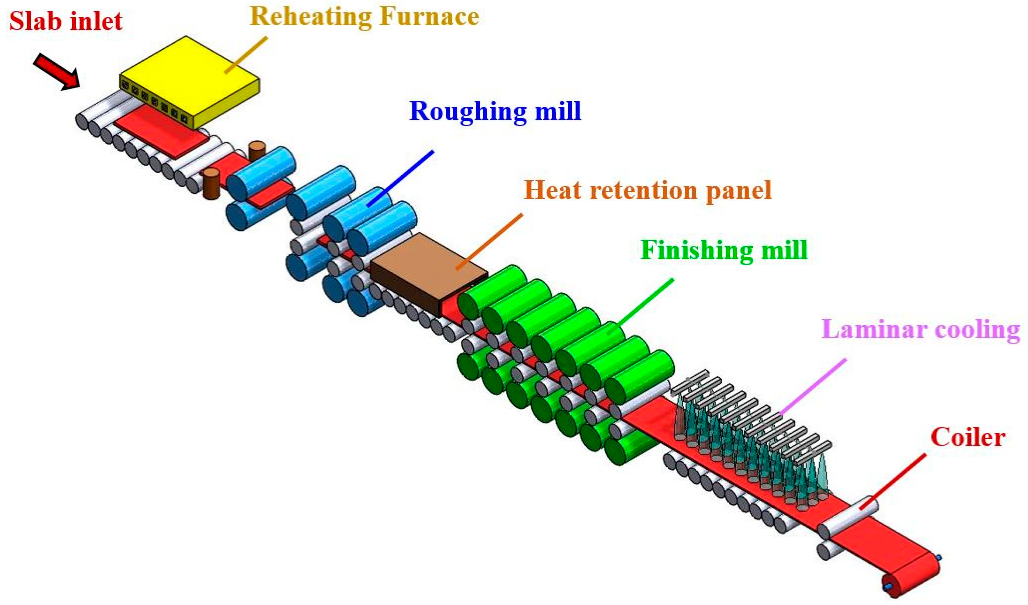
:1. Introduction
2. Mathematical Analysis
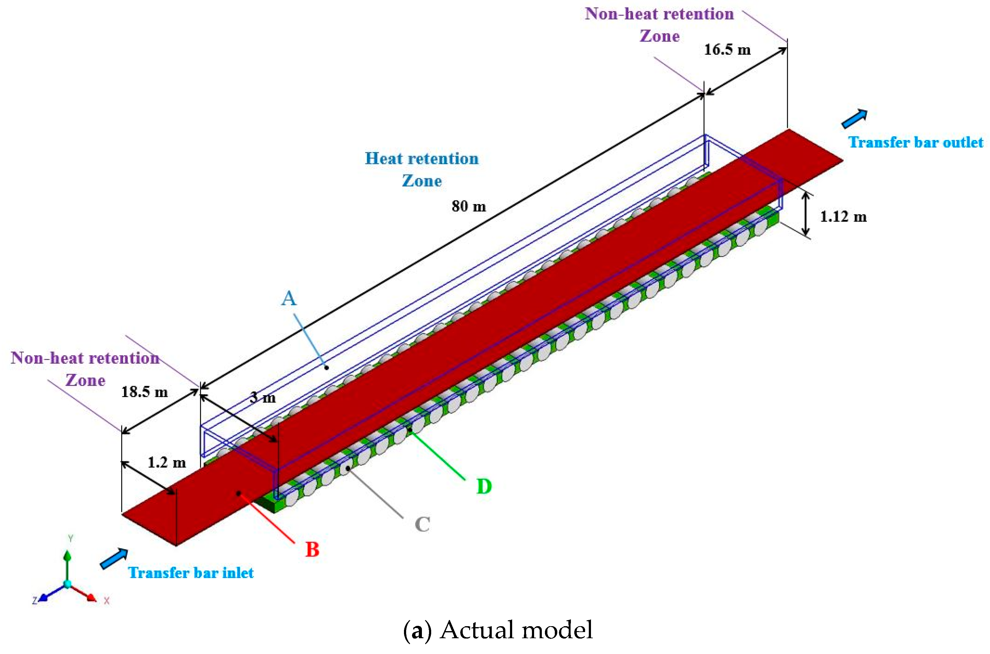
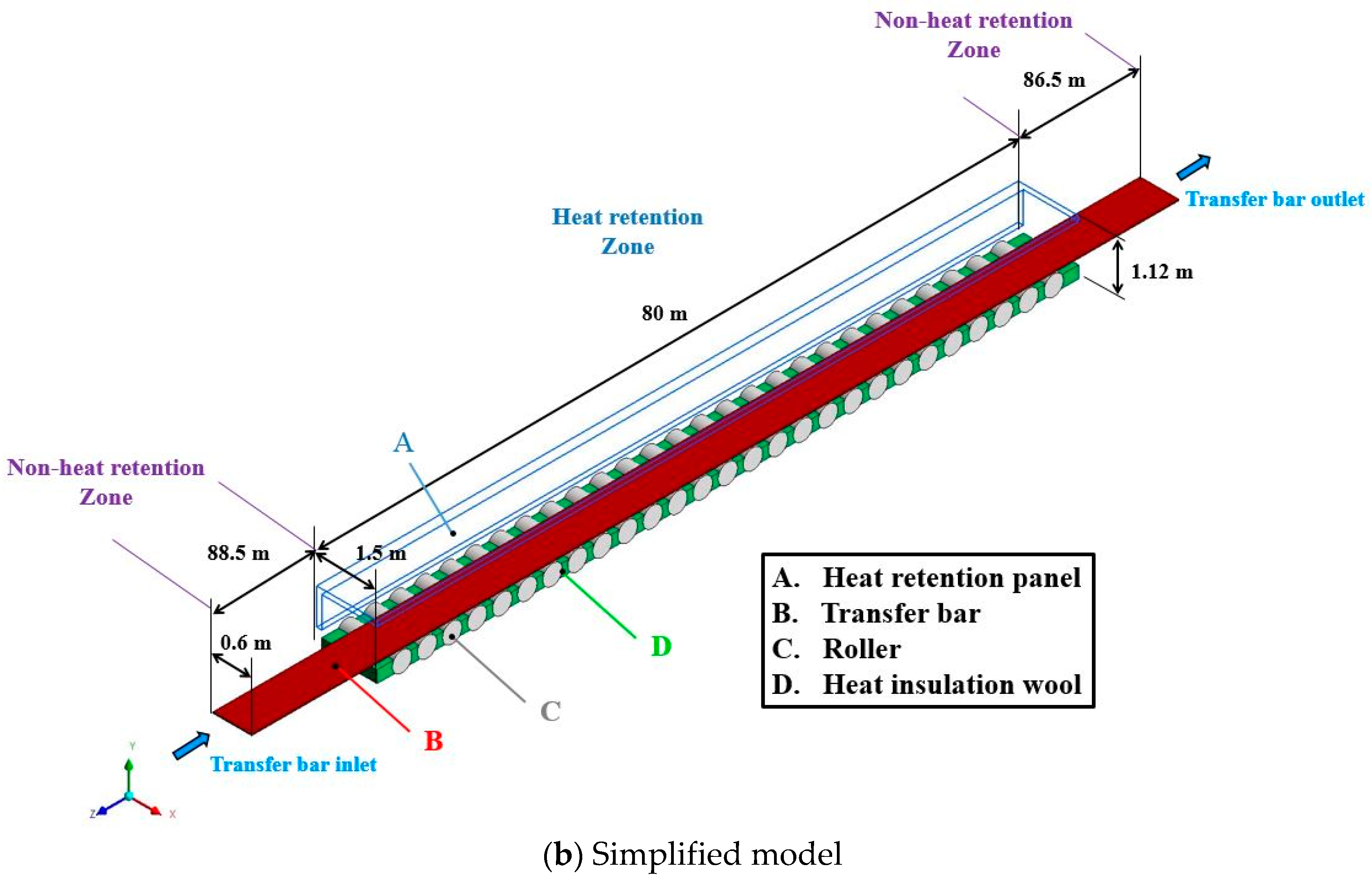
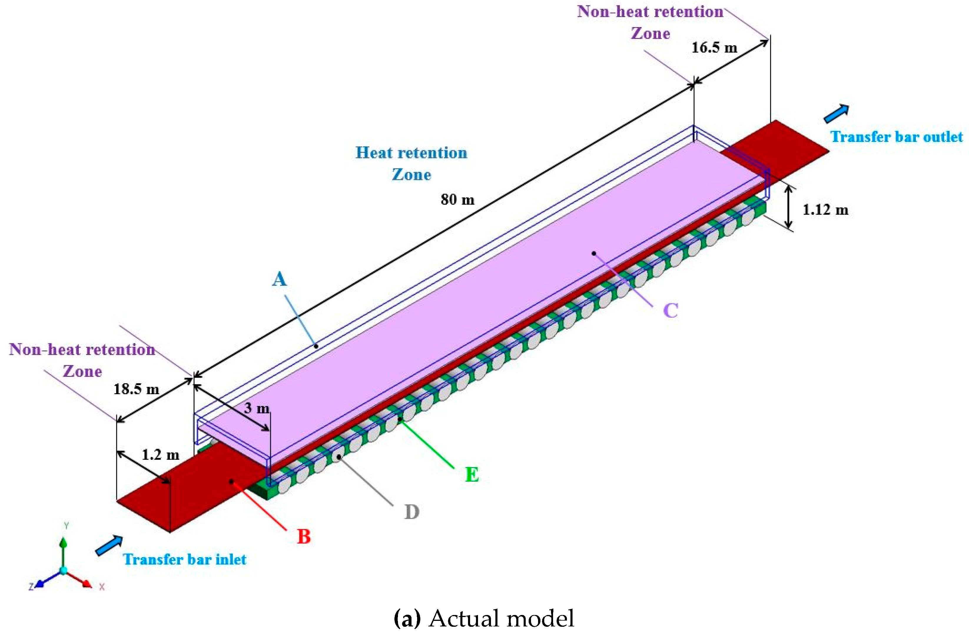
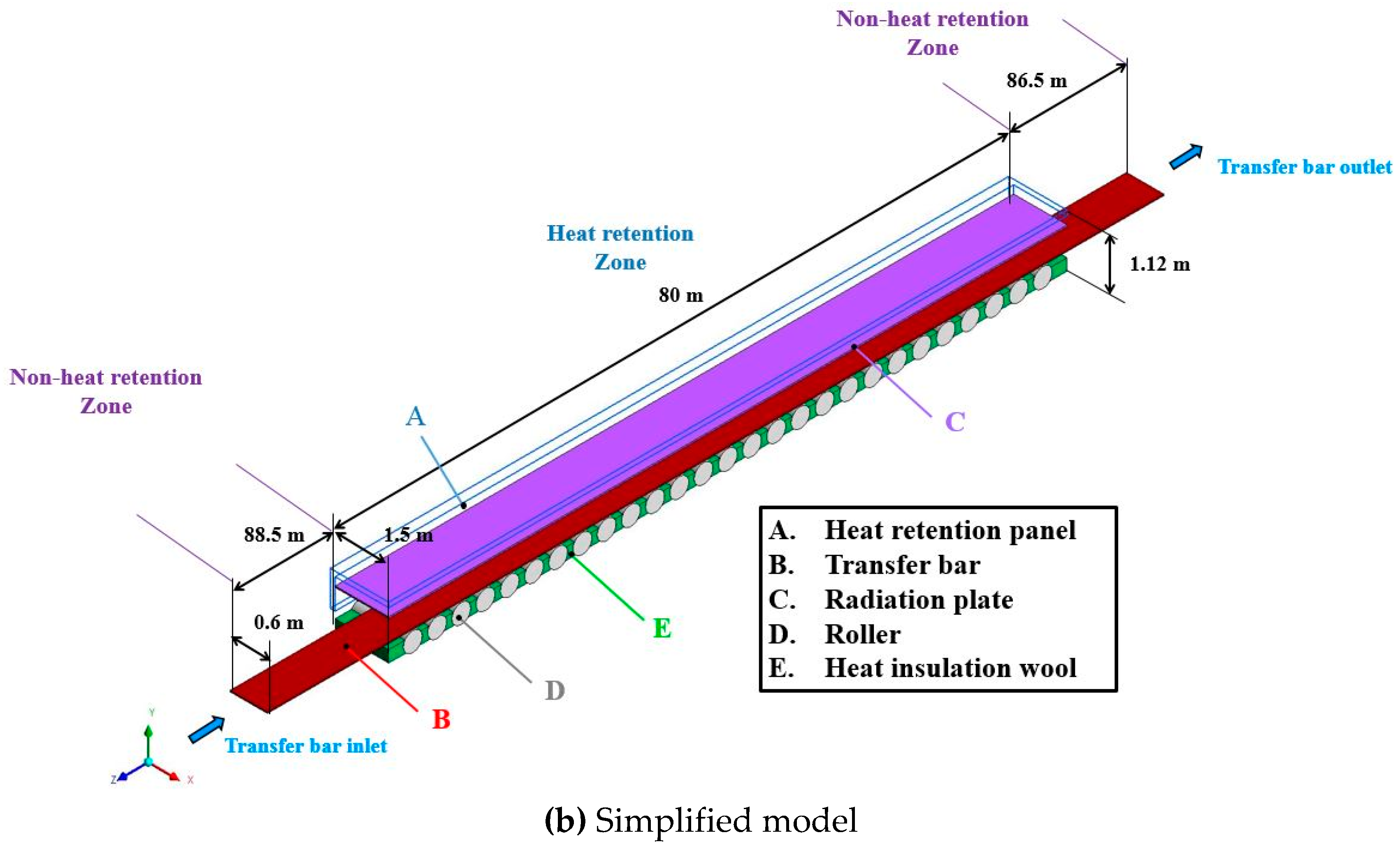
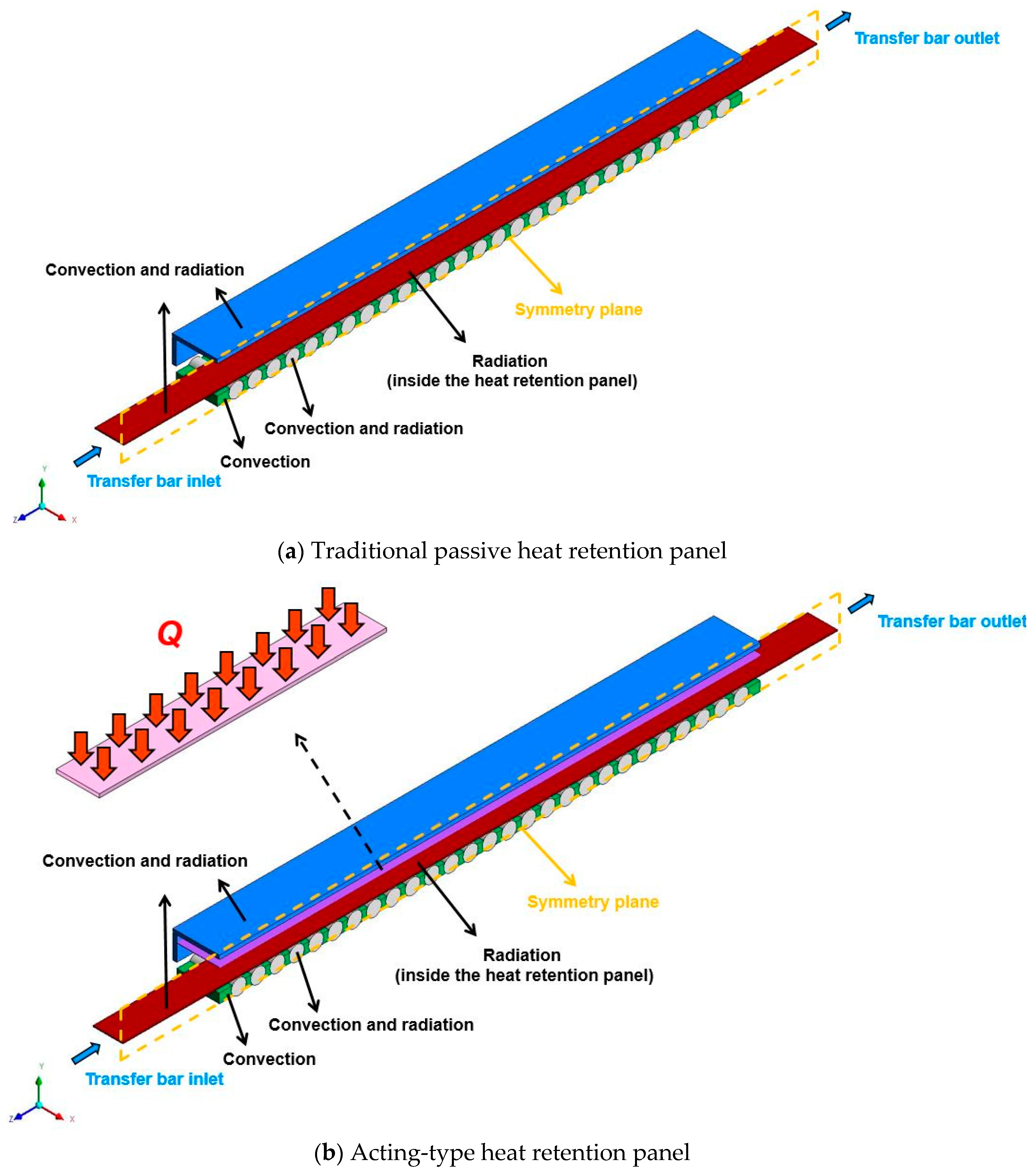
2.1. Physical Model
2.2. Governing Equations and Boundary Conditions
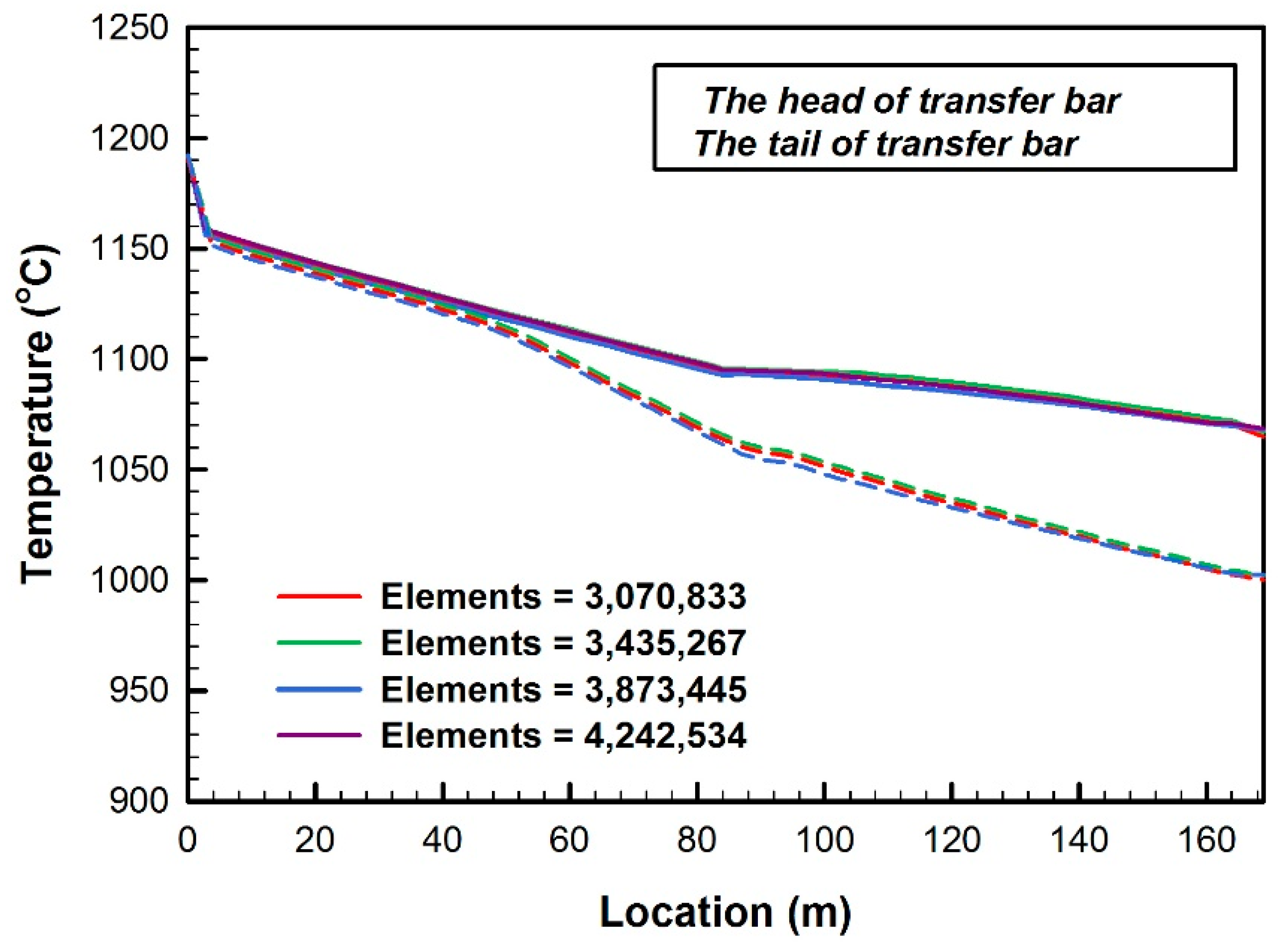
2.3. Numerical Methods and Grid Independence
3. Results and Discussion
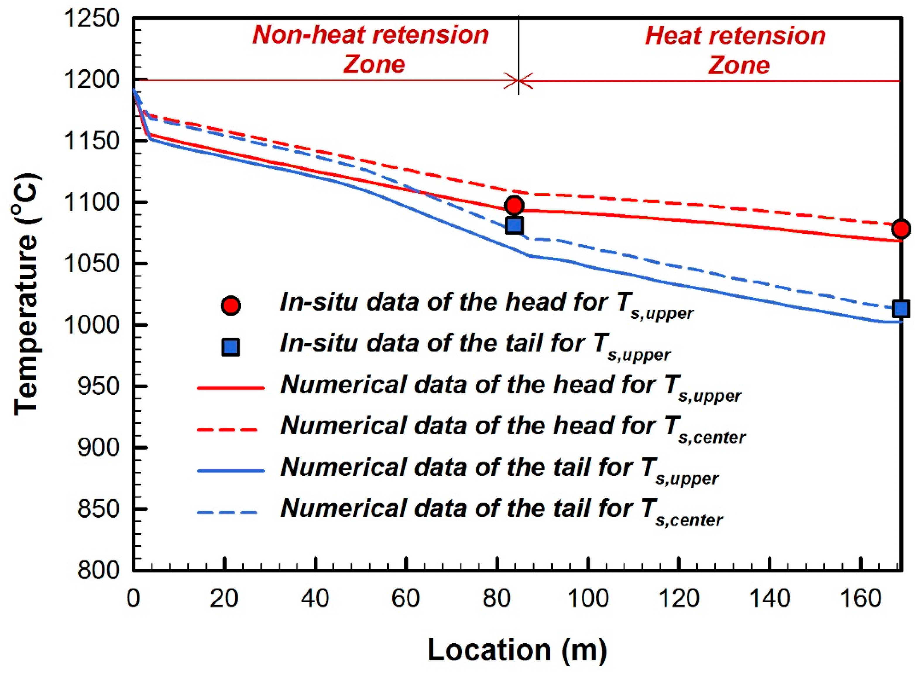
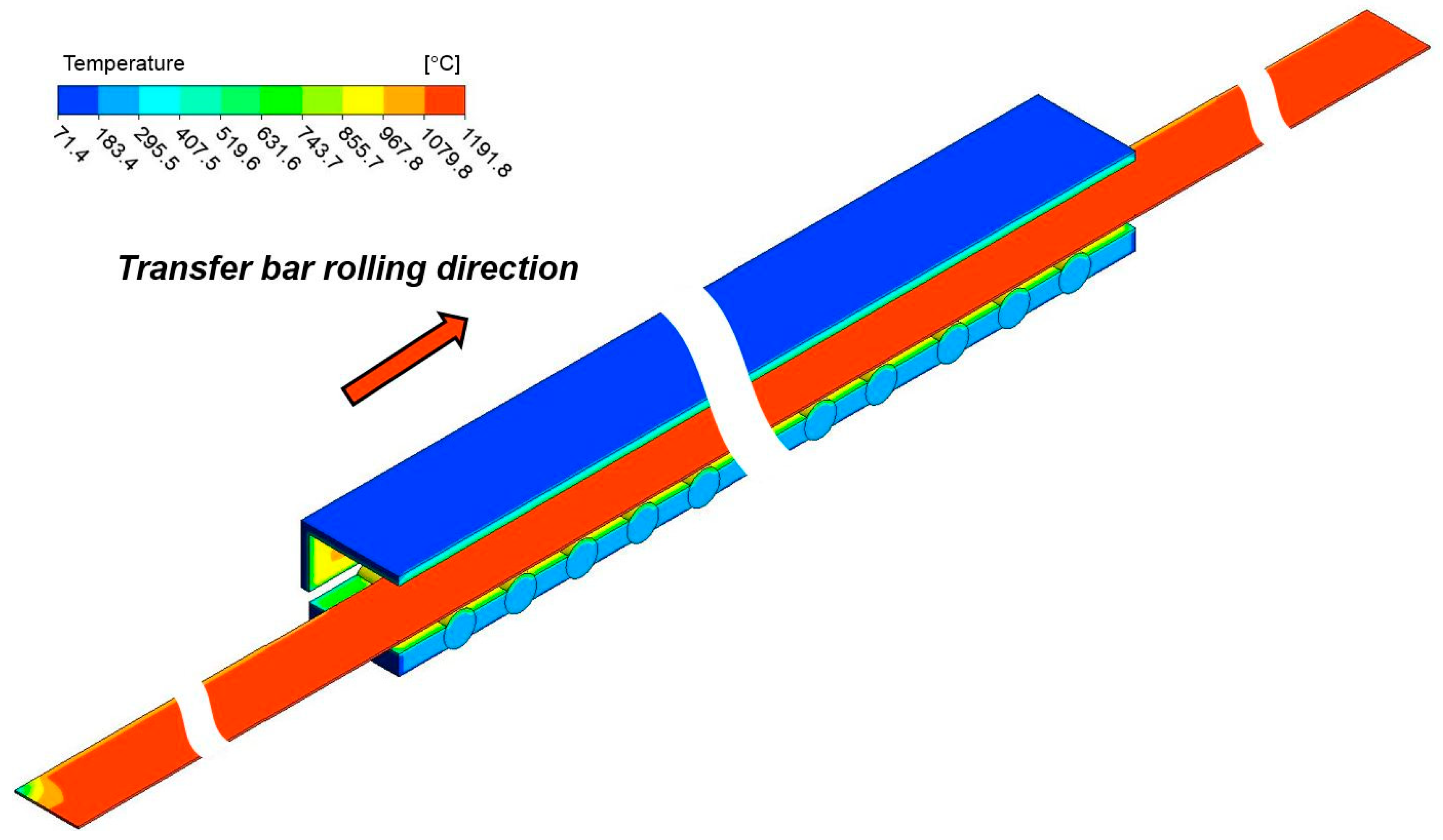
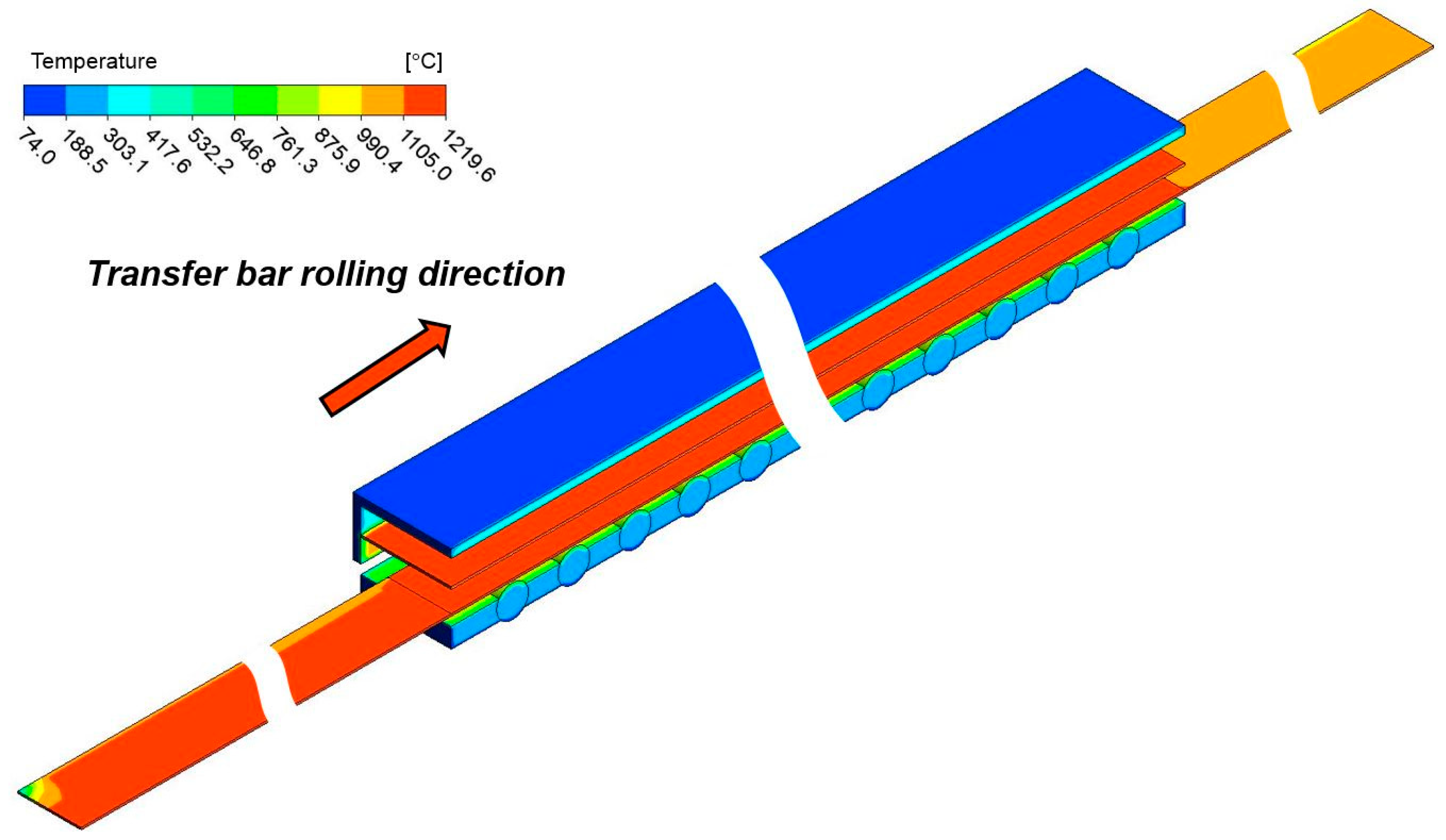
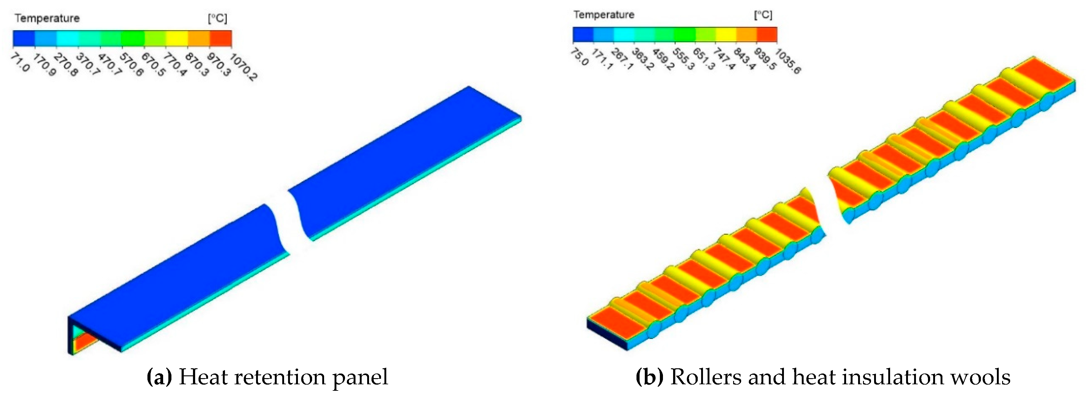
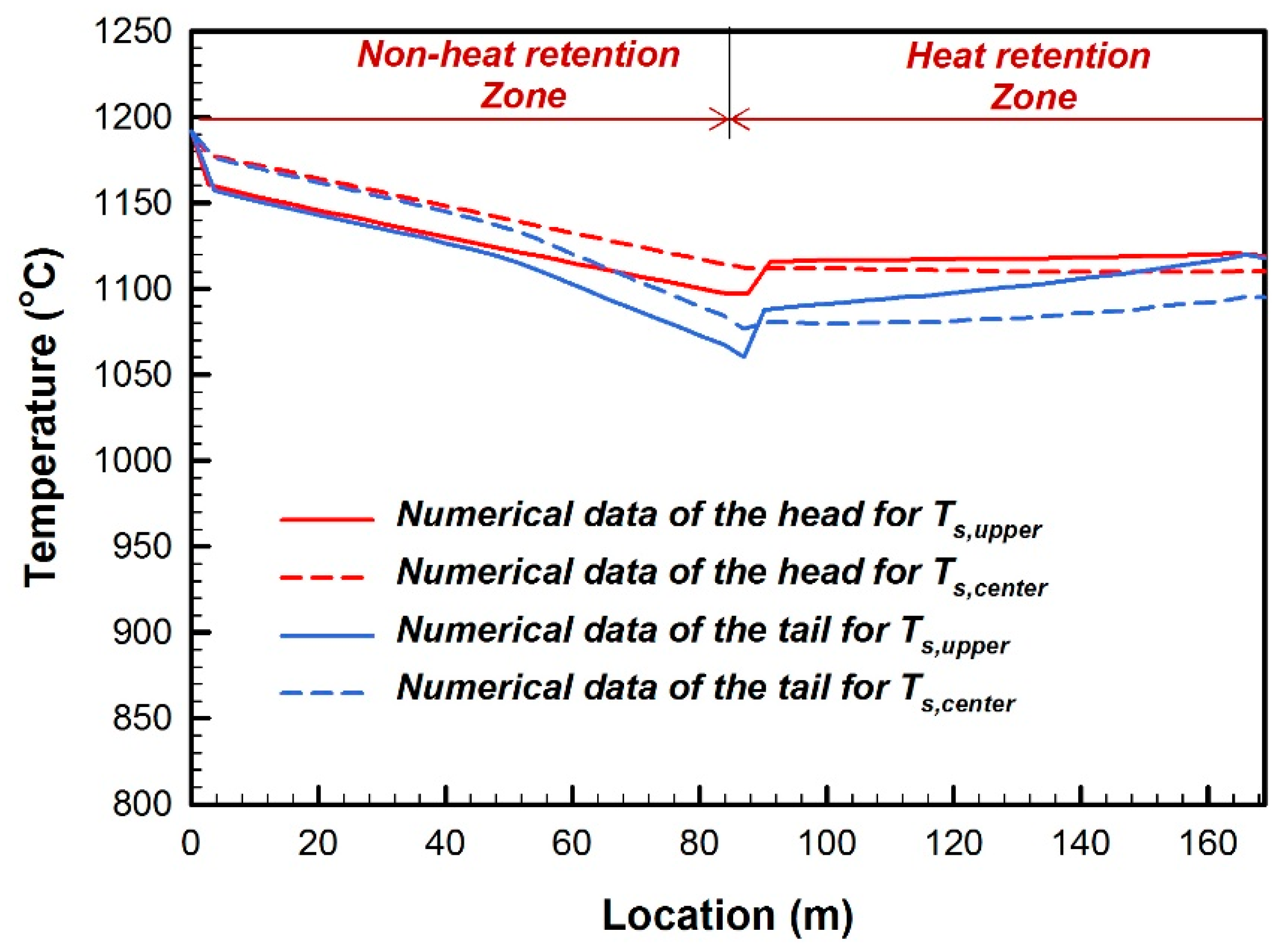
3.1. Traditional Passive Heat Retention Panel
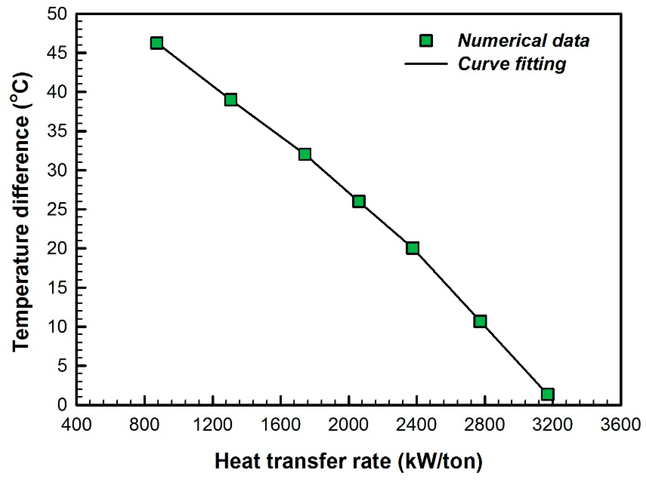
3.2. Acting-Type Heat Retention Panel
4. Conclusions
Author Contributions
Funding
Acknowledgments
Conflicts of Interest
Nomenclature
| A | area (m2) |
| a | acceleration (m/s2) |
| Cp | specific heat (kJ/kg⋅K) |
| Fkj | view factor from k surface to j surface |
| h | convective heat transfer coefficient (W/m2⋅K) |
| k | thermal conductivity (W/m⋅K) |
| n | normal direction |
| P | pressure (Pa) |
| q | heat flux (W/m2) |
| R | numerical residual |
| T | temperature (°C) |
| t | time (s) |
| u,v,w | velocity (m/s) |
| x,y,z | coordinates |
| Greek symbols | |
| α | thermal diffusivity (m2/s) |
| δkj | Kronecker delta |
| ε | emissivity |
| φ | property of fluid |
| μ | viscosity (N s/m2) |
| ρ | density (kg/m3); reflectance |
| σ | Boltzmann’s constant (J/K) |
| ∑ | summation |
| Subscripts | |
| in | state of inlet |
| ∞ | surroundings |
| out | state of outlet |
| s | surface |
| Superscripts | |
| C | convection |
References
- Wang, P.; Duan, W. Research and Development of Temperature Holding Hood for Hot Charging of Continuous Casting Slab; The Production Department of WISCO: Wuhan, China, 2003. [Google Scholar]
- Bu, H. Simulating and Analyzing of Intermediate Table Insulation Technology in Hot Continuous Rolling. Master’s Thesis, Wuhan University of Science and Technology, Wuhan, China, 2007. [Google Scholar]
- Zhang, P.; Zhang, N.; Li, Y. Numerical Simulation of Temperature Field During the Multi-pass Hot Strip Rolling in Temperature Holding Hood. Metall. Equip. 2007, 163, 5–8. [Google Scholar]
- Zhang, P.; Li, Y.; Li, Y.; Zhang, N.; Xiao, H. The simulation of Temperature Field of Hot Rolling Intermediate Billet. In Proceedings of the CSM Annual Meeting 2007, Chengdu, China, 15–17 November 2007. [Google Scholar]
- Bu, H. Effect of Heat Preservation Technology on Power Parameters of Finish Rolling in Hot Continuous Rolling; College of Materials Science and Metallurgical Engineering, Wuhan University of Science and Technology: Wuhan, China, 2008. [Google Scholar]
- Ling, A. Comparison and Choice of the Temperature Maintaining Equipment in the Thin Slab Continuous Casting and Rolling. Metal Mater. Metall. Eng. 2009, 37, 36–38. [Google Scholar]
- Speicher, K.; Steinboek, A.; Kiefer, T.; Kugi, A. Modeling Thermal Shocks and Air Cooling Using the Finite Difference Method. IFAC 2012, 45, 364–368. [Google Scholar] [CrossRef]
- Legrand, N.; Weisz-Patrault, D.; Horsky, J.; Luks, T.; Labbe, N.; Picard, M.; Ehrlacher, A. Characterization of Roll Bite Heat Transfers in Hot Steel Strip Rolling and Their Influence on Roll Thermal Fatigue Degradation; Trans Tech Publications: Zurich, Switzerland, 2013. [Google Scholar]
- Cheol, J.P.; Kang, S.Y.; Chang, H.L. Advanced temperature control of high carbon steel for hot strip mills. J. Mech. Sci. Technol. 2009, 24, 1011–1017. [Google Scholar]
- MEI, R.B.; Li, C.S.; Liu, X.H.; Han, B. Analysis of Strip Temperature in Hot Rolling Process by Finite Element Method. J. Iron Steel Res. Int. 2010, 17, 17–21. [Google Scholar] [CrossRef]
- Shulkosky, R.A.; Rosburg, D.L.; Chapman, J.D.; Barnes, K.R. A Microstructure Evolution Model Used For Hot Strip Rolling. In Proceedings of the Materials Science & Technology Conference, Chicago, IL, USA, 9–12 November 2003. [Google Scholar]
- Panjkovic, V. Model for prediction of strip temperature in hot strip steel mill. Appl. Therm. Eng. 2007, 27, 2404–2414. [Google Scholar] [CrossRef]
- Grajcar, A.; Skrzypczyk, P.; Wozniak, D.; Kolodziej, S. Semi-industrial simulation of hot rolling and controlled cooling of Mn-Al TRIP steel sheets. J. Achiev. Mater. Manuf. Eng. 2013, 57, 38–47. [Google Scholar]
- Tudball, A.; Brown, S.G.R. Practical finite element heat transfer modelling for hot rolling of steels. Ironmak. Steelmak. 2006, 33, 61–66. [Google Scholar] [CrossRef]
- Delpature, Y.; Fantuzzi, M.; Filippi, E.; Venanzini, M. Transfer bar reheating in hot strip mills with the Active Tunnel Furnace (ATF). Millennium Steel 2006, 28, 180–182. [Google Scholar]
- ANSYS Fluent, Version, 18.1 User’s Guide, USA; Fluent Inc.: Lebanon, NH, USA, 2018.


| Material | ρ (kg/m3) | Cp (J/kgK) | k (W/m K) | Emissivity |
|---|---|---|---|---|
| Transfer bar | 8030 | 550 | 23.8 | 0.75 |
| Heat retention panel | 400 | 1130 | 1.5 | 0.90 |
| Radiation plate | 7940 | 460 | 32.0 | 0.50 |
| Roller | 7700 | 421 | 33.2 | 0.50 |
| Heat insulation wool | 400 | 1313 | 0.3 | 0.10 |
| R2DT | FET | |||||
|---|---|---|---|---|---|---|
| Num. (°C) | In-Situ (°C) | Deviation (%) | Num. (°C) | In-Situ (°C) | Deviation (%) | |
| Head | 1092.78 | 1097.00 | 0.38 | 1068.24 | 1078.00 | 0.91 |
| Tail | 1061.55 | 1081.00 | 1.79 | 1002.58 | 1013.33 | 1.06 |
| ΔT | 31.23 | 16.00 | - | 65.66 | 64.67 | - |
| Num. (°C) | In-Situ (°C) | Deviation (%) | ||
|---|---|---|---|---|
| Heat retention panel | Outer surface | 114 | 100~150 | 8.80 |
| Inner surface | 711 | 600~750 | 5.33 | |
| Rollers | Upper surface | 622 | 600~700 | 4.31 |
| Lower surface | 238 | 200~300 | 4.80 | |
| R2DT | FET | |||
|---|---|---|---|---|
| Temperature (°C) | Case 1 | Case 2 | Case 1 | Case 2 |
| Head | 1096.72 | 1096.72 | 1112.73 | 1121.44 |
| Tail | 1065.73 | 1065.73 | 1081.51 | 1119.47 |
| ΔT | 30.99 | 30.99 | 31.22 | 1.97 |
| Temperature (°C) | Case 1 | Case 2 | |
|---|---|---|---|
| Heat retention panel | Outer surface | 130.95 | 131.76 |
| Inner surface | 916.17 | 1326.50 | |
| Rollers | Upper surface | 775.31 | 799.42 |
| Lower surface | 227.51 | 251.69 | |
© 2019 by the authors. Licensee MDPI, Basel, Switzerland. This article is an open access article distributed under the terms and conditions of the Creative Commons Attribution (CC BY) license (http://creativecommons.org/licenses/by/4.0/).
Share and Cite
Jang, J.-Y.; Guo, J.-W.; Chang, C.-C. The Heat Transfer Analysis of an Acting-type Heat Retention Panel used in a Hot Rolling Process. Appl. Sci. 2019, 9, 189. https://doi.org/10.3390/app9010189
Jang J-Y, Guo J-W, Chang C-C. The Heat Transfer Analysis of an Acting-type Heat Retention Panel used in a Hot Rolling Process. Applied Sciences. 2019; 9(1):189. https://doi.org/10.3390/app9010189
Chicago/Turabian StyleJang, Jiin-Yuh, Jin-Wei Guo, and Chih-Chung Chang. 2019. "The Heat Transfer Analysis of an Acting-type Heat Retention Panel used in a Hot Rolling Process" Applied Sciences 9, no. 1: 189. https://doi.org/10.3390/app9010189
APA StyleJang, J.-Y., Guo, J.-W., & Chang, C.-C. (2019). The Heat Transfer Analysis of an Acting-type Heat Retention Panel used in a Hot Rolling Process. Applied Sciences, 9(1), 189. https://doi.org/10.3390/app9010189