1. Introduction
Chaotic system is a complex nonlinear system. In recent years, it has attracted extensive attention in the field of engineering research. The reason is that chaotic systems have very rich dynamic behavior, unpredictable trajectory, white noise-like broadband and the initial value sensitivity of the butterfly effect. The chaos dynamics in most mechanical engineering systems is undesirable and needs to be suppressed because it will affect the performance or damage the mechanical structure of systems. In 1990, O.G.Y (Ott, Grebogi and Yorke) [
1] proposed the study of chaos control. Researchers pointed out that, when parameter values of chaotic systems are slightly modulated, the chaotic behavior will produce huge and unpredictable changes. Several feedback control methods to suppress chaos behavior have been proposed in the literature [
2,
3]. Although the chaos behavior might be undesired in most mechanical systems, the noise-like behavior of chaos is useful to the application of image encryption and secure communication [
4,
5,
6,
7,
8]. Due to the practical application of chaos synchronization, since the pioneering research of Pecora and Carroll [
9], chaos synchronization has become an interesting research field. Many control methods have been proposed to solve the synchronization problem for chaotic systems, such as
H∞ control [
10,
11], fuzzy sliding mode control [
12,
13], adaptive control [
14,
15] and so forth. Among proposed control designs, sliding mode control method is often the first choice for researchers because it is not sensitive to system parameters and external disturbances and with good robustness.
In these two decades, chaotic systems have been widely applied in the areas of communication, medicine and biology to solve several important engineering problems, especially in the security field of communication. In the previous reports [
4,
5,
6], the authors used the continuous chaotic systems with well-designed synchronization controllers to achieve the secure communication. However, in practical circuit implementations for continuous chaotic systems, analog components, such as operational amplifier (OPA), resistors, capacitors are necessary. Unfortunately, these analog components are sensitive to environmental conditions and often result in circuit instability. On the other hand, owing to the progress of microcontrollers with digital signal processing (DSP) technology, using microcontrollers to replace the analog circuits has become more and more popular and important. Discrete chaotic systems implemented by the microcontroller are more robust and less susceptible to temperature variation and component aging but also at a lower price. Therefore, to solve the problem of instability of analog circuits, we need to study the discrete chaotic systems realized by microcontrollers. Until now, the applications of discrete chaotic systems to solve image encryption have been proposed in References [
7,
8]. However, the synchronization control problem of discrete chaotic systems has not been well solved in these studies. In addition, to the best of our knowledge, using discrete chaotic systems to design the synchronized large-scale CRNGs has not been well discussed. Furthermore, recently, due to the advent of quantum computers, many traditional encryption methods may become unsafe. The encryption can be quickly cracked by quantum computers. Because the chaos system has rich dynamic characteristics, it can generate a large amount of random signals in a very short time and many scholars have pointed out that chaotic encryption method may be one of the solutions against the attack of quantum computers [
16,
17].
For the above reasons, in this paper, we study the design of synchronized large-scale CRNGs and its application to secure communication. In order to simplify the presentation of the paper, we choose Duffing map for this study. However, the proposed modulation approach can also effectively applied to other classes of discrete chaotic systems. First, we introduce a modulation approach by introducing some parameters into the chaotic Duffing map to regulate and increase the diversity of chaotic state responses. Then we implement the proposed modulated Duffing map systems under different initial conditions by the microcontroller. Due to the butterfly effect, the state response of each Duffing map system will be quite different. Therefore, we can get a large amount of random chaotic states and complete the design of large-scale CRNGs. For subsequent communication security application, we use sliding mode control to cope with the synchronization problem of the master-slave large-scale CRNGs. Finally, the above results are integrated to realize an innovative secure communication system to prove the correctness and feasibility of the research.
2. Design of a Large-Scale CRNG
In this paper, we will discuss the design and realization of a large-scale CRNGs and its application to secure communication based on synchronized master-slave large-scale CRNGs. To design the large-scale CRNGs, in the following, we first introduce the modulation of the Duffing map chaotic system such that diversified random chaotic state responses can be obtained for large-scale CRNGs. The original Duffing map system is described by the following system.
where
are the system states. In order to adjust the amplitude and DC offset for state responses, we define new state variables
satisfying
where
are given to adjust the amplitude and the DC offset of state responses, respectively. From Equation (2), we have
By (1) and (3), a new modulated Duffing map chaotic system can be obtained as
where
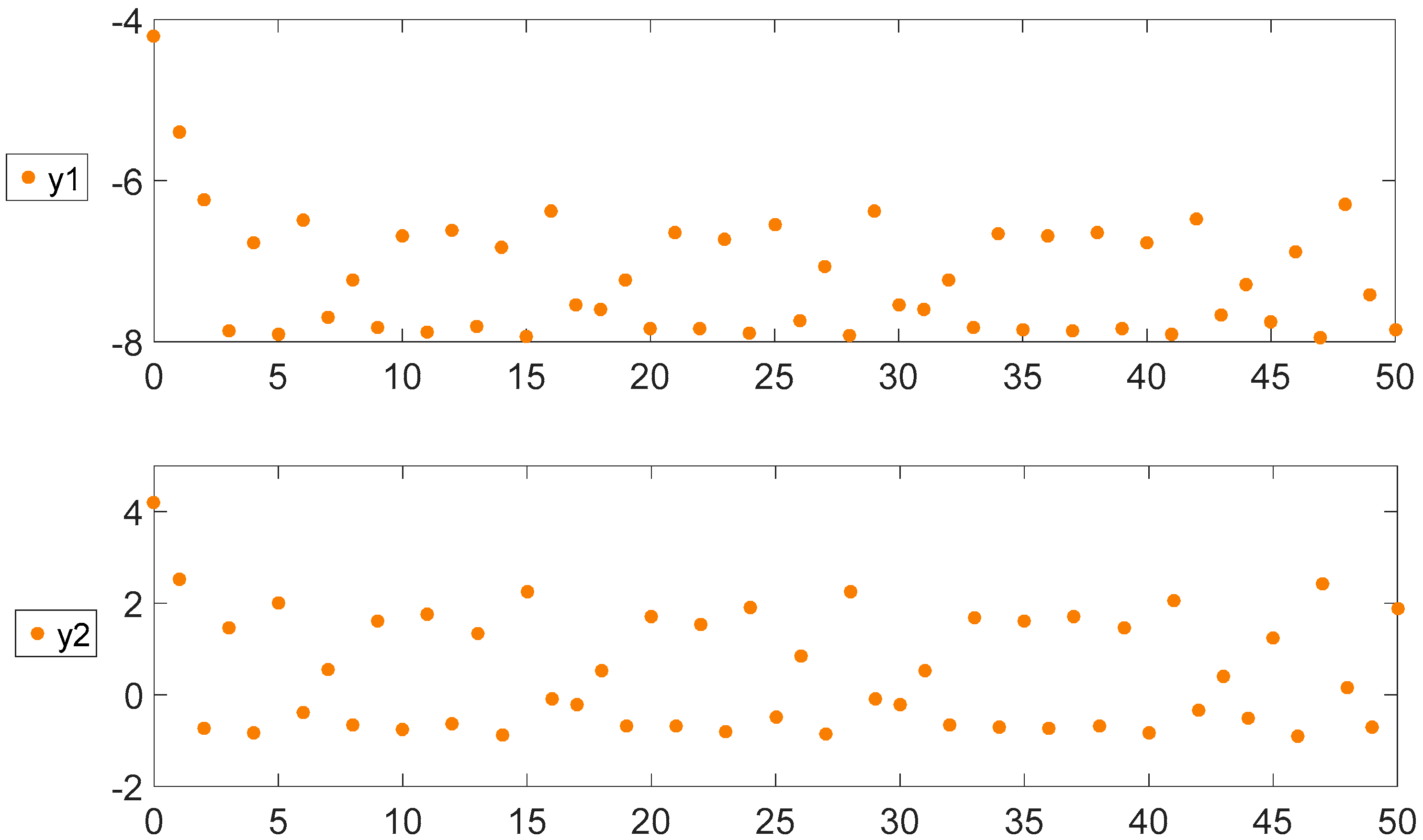
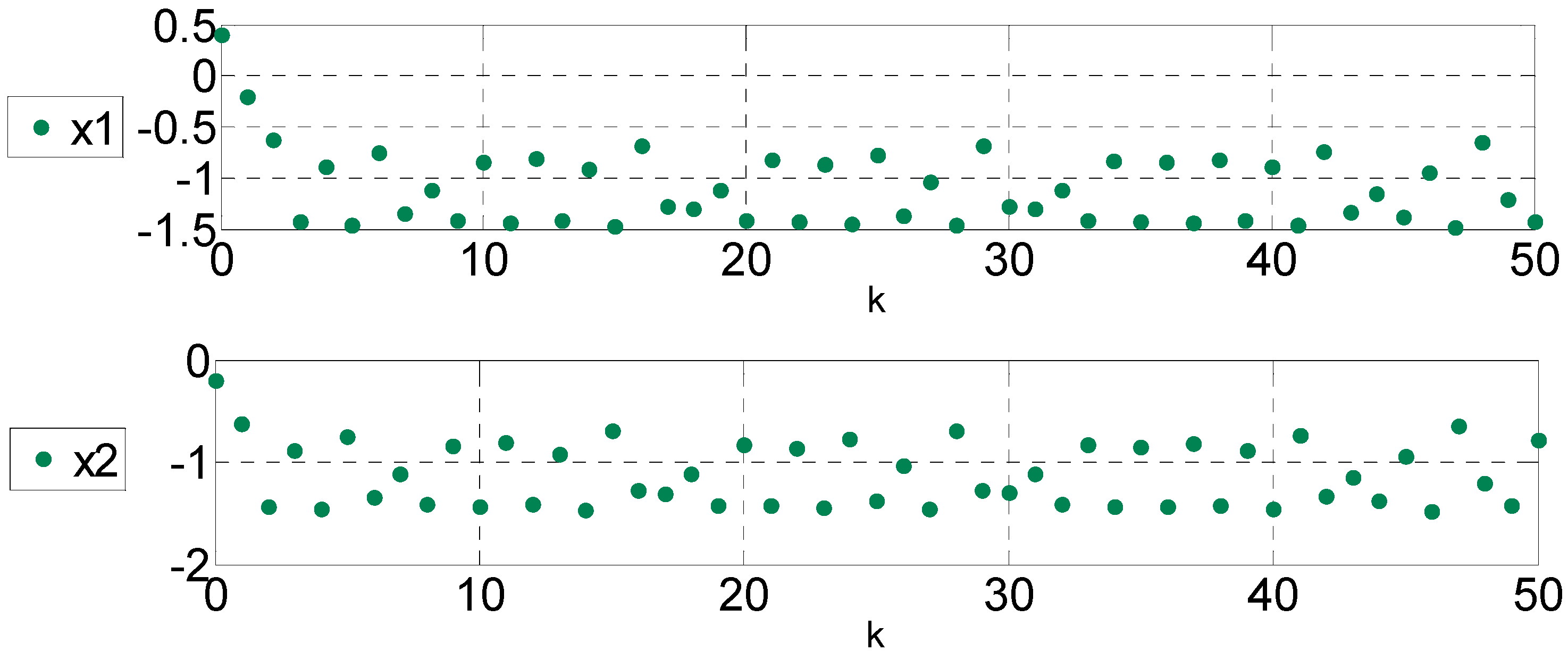
For evaluating the modulation of the system amplitude and DC offset of random number generator, we give the following simulation analysis. In the simulation, the modulation parameters are given as
and the initial conditions are selected as
. The simulation results are given in
Figure 1,
Figure 2 and
Figure 3.
According to the simulation results above, it reveals, as expected, the amplitude is modulated by 2 times and 4 times, while the DC offset is shifted by −5 and 5. Furthermore, we use the National Institute of Standards and Technology (NIST) [
18] test suite to test the randomness of the modulated chaotic states. In the NIST test, first, we set the test parameters including the sequences length
n = 2 × 10
7 bits, the number of subsequences,
. Then, we take byte 5 (bits 32~39) of every modulated chaos states y1 and y2 in IEEE754 double-precision format [
19] to test the randomness. Finally, all the test results are shown in
Table 1. In
Table 1, the outcome of the test values is called p value. When
, then it passes the test. From
Table 1, the generated numbers of y1 pass all tests and those of y2 pass 13 tests. Therefore, we can conclude that the modulated chaotic states are with good randomness.
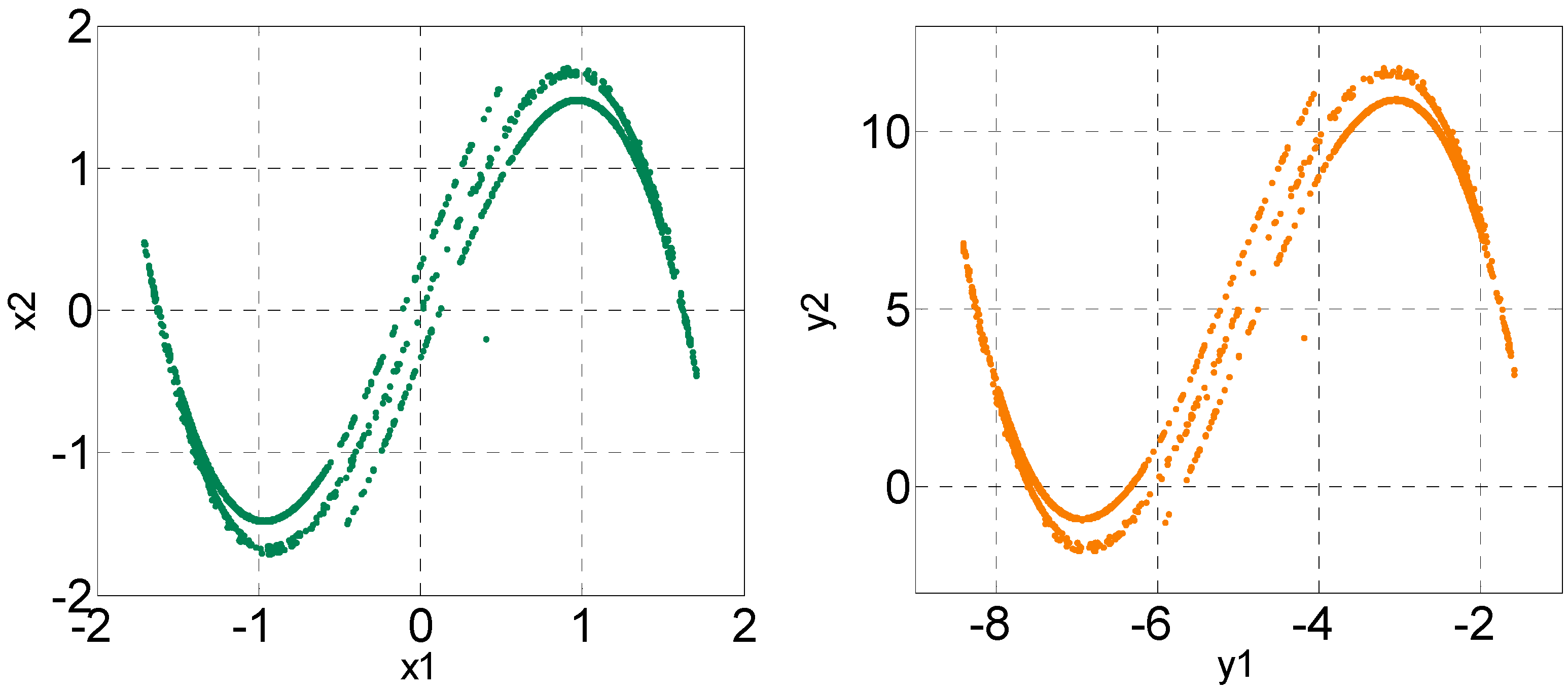
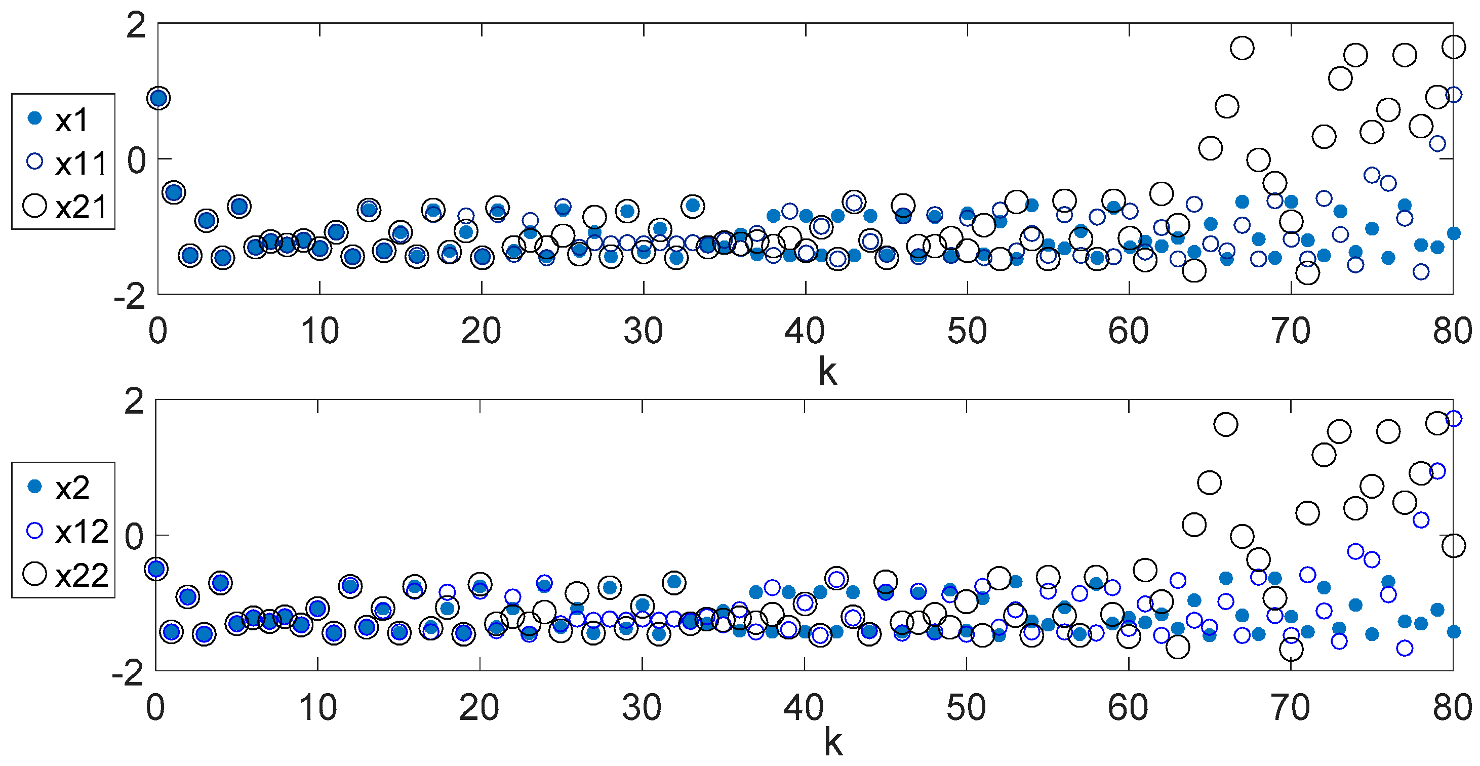
From discussed above, the random number generator can be implemented by using the modulated Duffing map chaotic system. It is well known that the state response of a chaotic system is very sensitive to initial values and very small differences can lead to very different chaotic state responses, namely the butterfly effect. Based on this feature, we can use the butterfly effect to design large-scale CRNGs. In addition, due to the high capacity and fast computing speed of the digital microcontroller, we can implement this large-scale CRNG with microcontroller and can get a large amount of random numbers in the very short time according to the computing speed of the microcontroller. To show the butterfly effect, we use three sets of random generators (Duffing map systems in (1)) for comparison.
is the random number of the first random number generator, the second is
and the third is
. The initial conditions are selected as
,
, respectively. From the simulation results in
Figure 4, it can be found that the initial values with very small difference, as expected, will produce completely different random state responses.
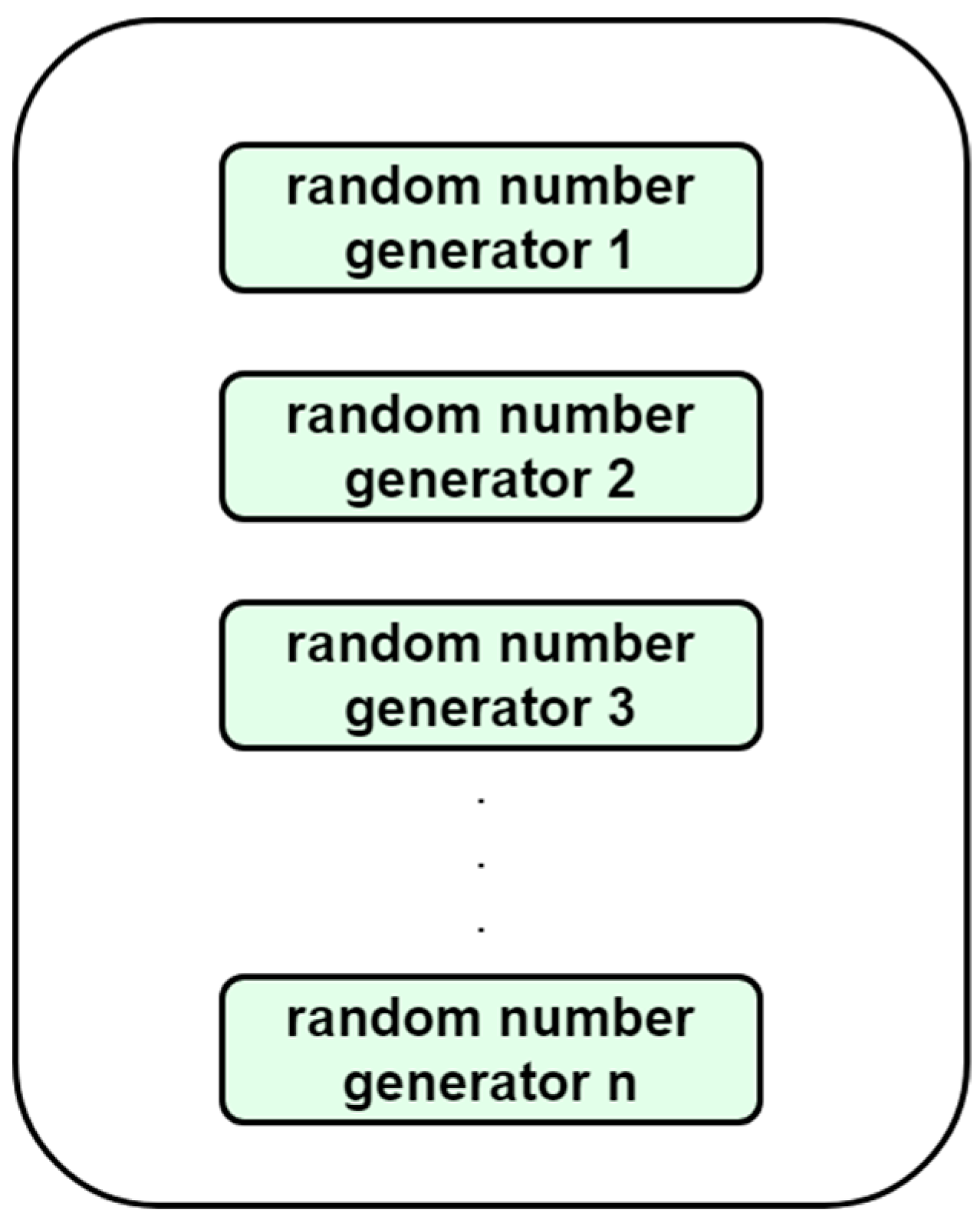
Now we are ready to implement the large-scale CRNG. Its structure is designed as shown in
Figure 5. We construct n Duffing maps with the same structure in the microcontroller. Each Duffing map has different initial values. According to the butterfly effect mentioned above, we can get 2n random numbers. It is worth mentioning that the microcontrollers have a large amount of program memory capacity and fast computing speed, which means that we can use the microcontroller to complete the large-scale CRNG in
Figure 5 and obtain a large amount of random numbers in a very short period time.
In the following, we continue to discuss the realization of the proposed large-scale CRNG in
Figure 5. First, we construct ten sets (
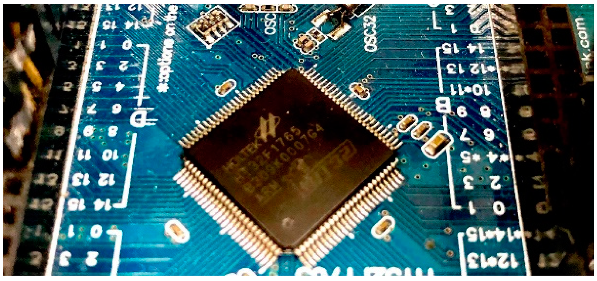
n = 10) of CRNGs by using the HT32F1765 microcontroller as shown in
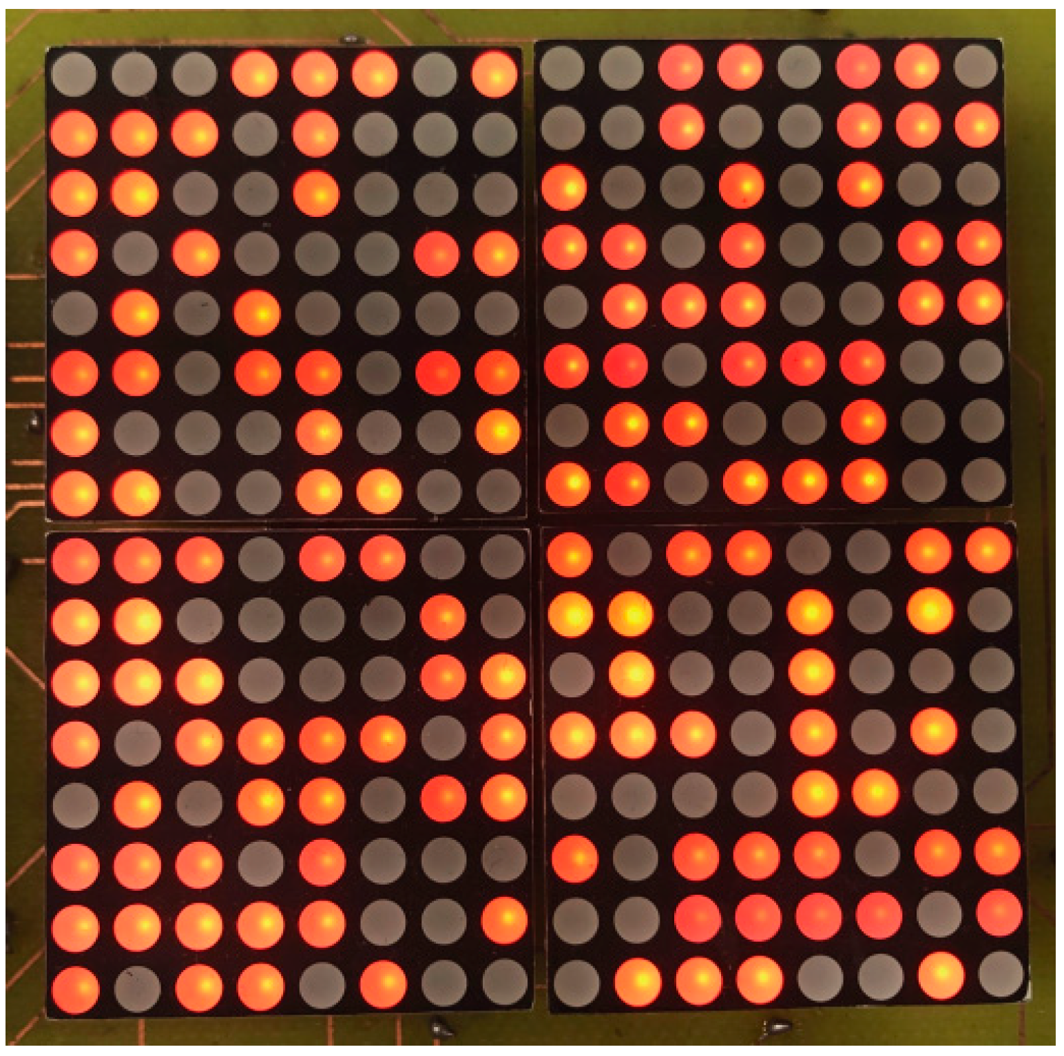
Figure 6. The HT32F1765 operates at a frequency up to 72MHz with a Flash accelerator to obtain maximum efficiency. It provides 128KB of embedded Flash memory for code/data storage and up to 64 KB of embedded SRAM memory for system operation and application program usage. Due to the butterfly effect in the chaotic system, each set of CRNGs has different initial values, so the output responses of the CRNGs of each set will be completely different. When we set up 10 sets of CRNGs with different initial values, we can get 20 random numbers and then according to the IEEE 754 double-precision standard, each random floating-point value is represented with 64 bits. Therefore, we can get 1280 random binary bits (2 × 10 × 64). At the same time, if necessary, we can also build more chaotic systems in the HT32F1765 microcontroller to get more random bits. By using 8 × 8 LED matrix,
Figure 7 shows 256 random binary signals obtained from the proposed large-scale CRNG.
3. Synchronization of Master-Slave Large-Scale CRNGs
The design of large-scale CRNGs has been completed. We continue to study the synchronization of master and slave large-scale CRNGs. As mentioned above, the large-scale CRNG is composed of n chaotic CRNGs with the same structure, so the synchronization controller for each chaotic CRNGs will also have the same structure. Therefore, we first consider the design of a single master-slave CRNG. The master and slave CRNGs are defined, respectively, as below.
Master random number generator:
Slave random number generator:
where
and
are, respectively, the state variables of the master and slave systems.
is the control input introduced to achieve synchronization between the master and slave CRNGs. By defining
, the error dynamics can be obtained by the following equation:
In the following, the discrete sliding mode control (DSMC) is utilized to achieve the synchronization. Generally, the DSMC design is composed of two steps. First, we need to select an appropriate switching function for error dynamics (7) such that the sliding motion can ensure the convergence of the error states. Second, we need to propose a DSMC to guarantee the existence of the sliding mode and maintain the error dynamics on the sliding manifold [
2]. To achieve the synchronization based on DSMC, a switching function is selected as:
Assuming the error dynamics is already on the sliding manifold (
), we have
Substituting (9) into (7), we can obtain
From (10), we can see that if
is specified to satisfy
, than
converges to zero. Furthermore, since
in the sliding manifold, we obtain
when
. After discussing the selection of the switching surface, we still have to design the controller to ensure that the system can smoothly enter the sliding manifold such that
can be ensured. The controller design is described as follows. According to (7) and (8), we have
If the controller
is properly designed as:
where
. Substituting (12) into (11), we can get
Since is specified in (12), the error system can smoothly enter the sliding manifold, that is, . From the above discussion, we can confirm that the system can smoothly enter the sliding mode under the action of the controller (12) and the error states in (7) can also converge to zero as discussed above, that is, the master-slave CRNGs in (5) and (6) can achieve synchronization.
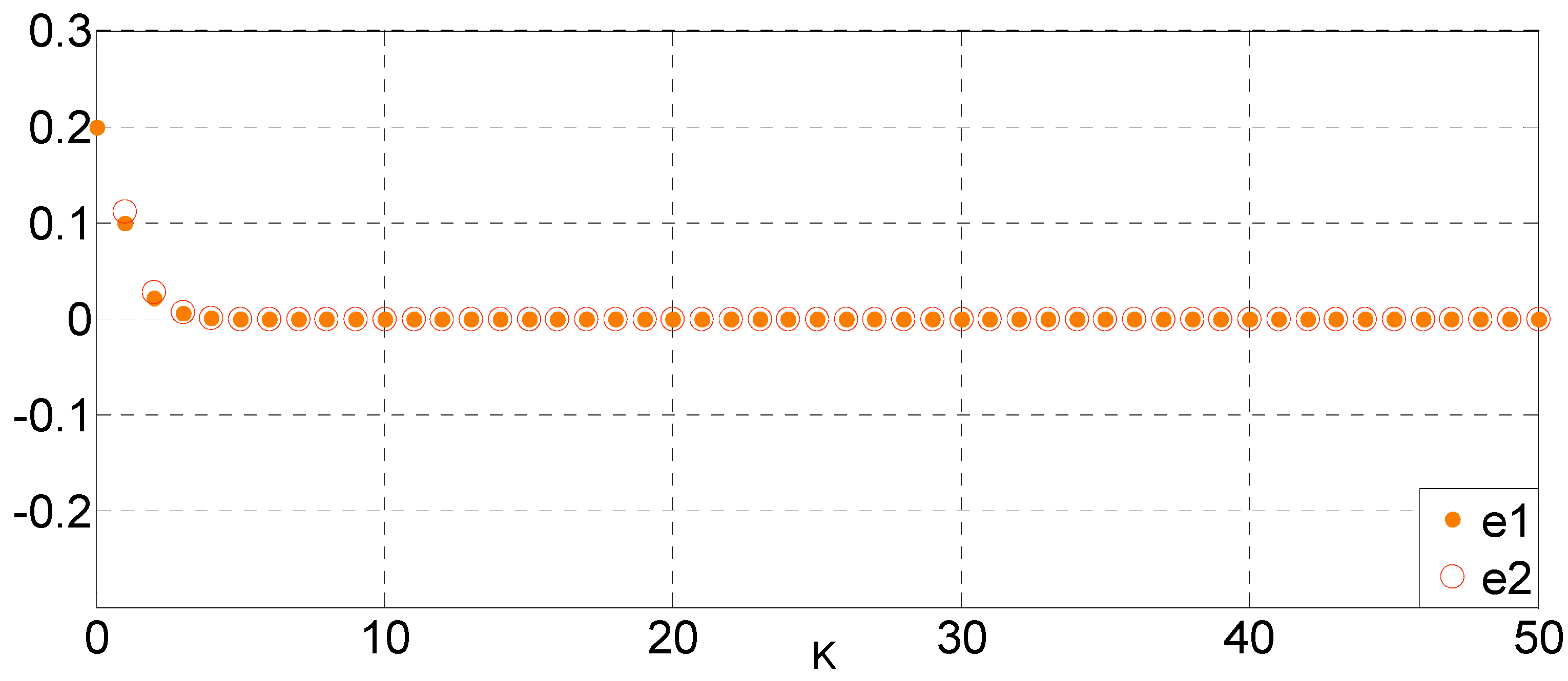
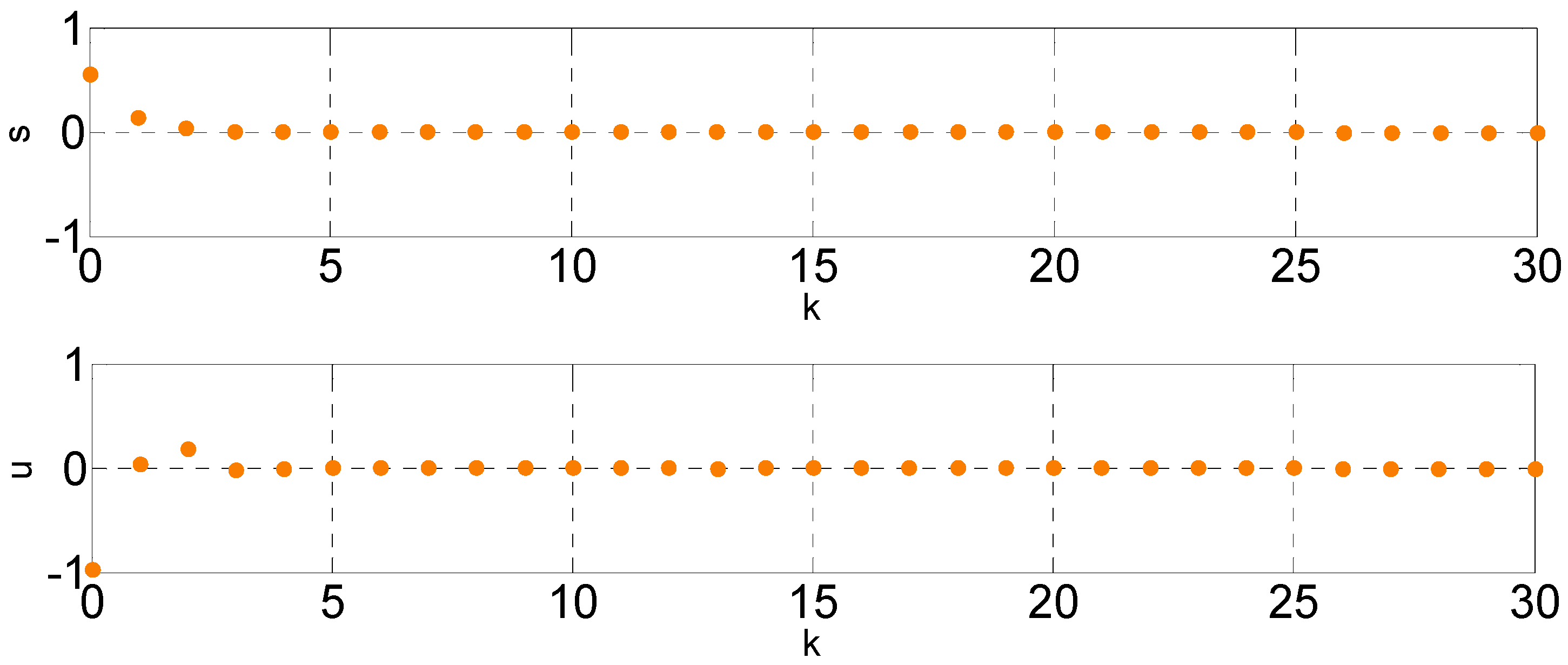
In the following, for evaluating the synchronization effect of master and slave CRNGs, the parameters are given as
. Therefore, the sliding mode control law can be obtained by (12) with
. In numerical simulations, the initial conditions are selected as
. The simulation results are shown in
Figure 8,
Figure 9,
Figure 10 and
Figure 11.
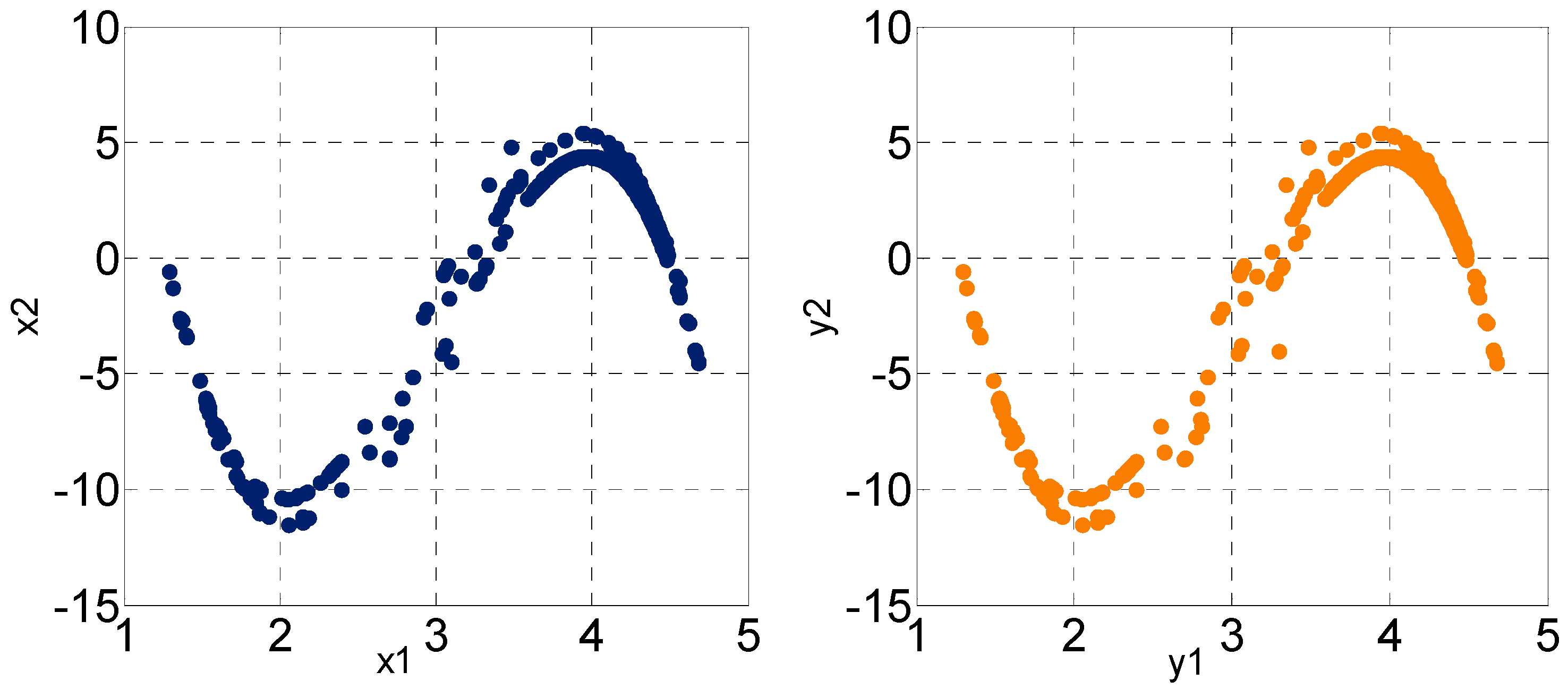
Figure 8 shows the corresponding state responses of master and controlled slave CRNGs.
Figure 9 shows the error response between master and controlled slave CRNGs.
Figure 10 and
Figure 11, respectively, show the switching function and control input and phase planes of the controlled master-slave CRNG. From the simulation results, it shows the proposed sliding mode control works well and the chaotic behavior of controlled master and slave random number generator can be asymptotically synchronized.
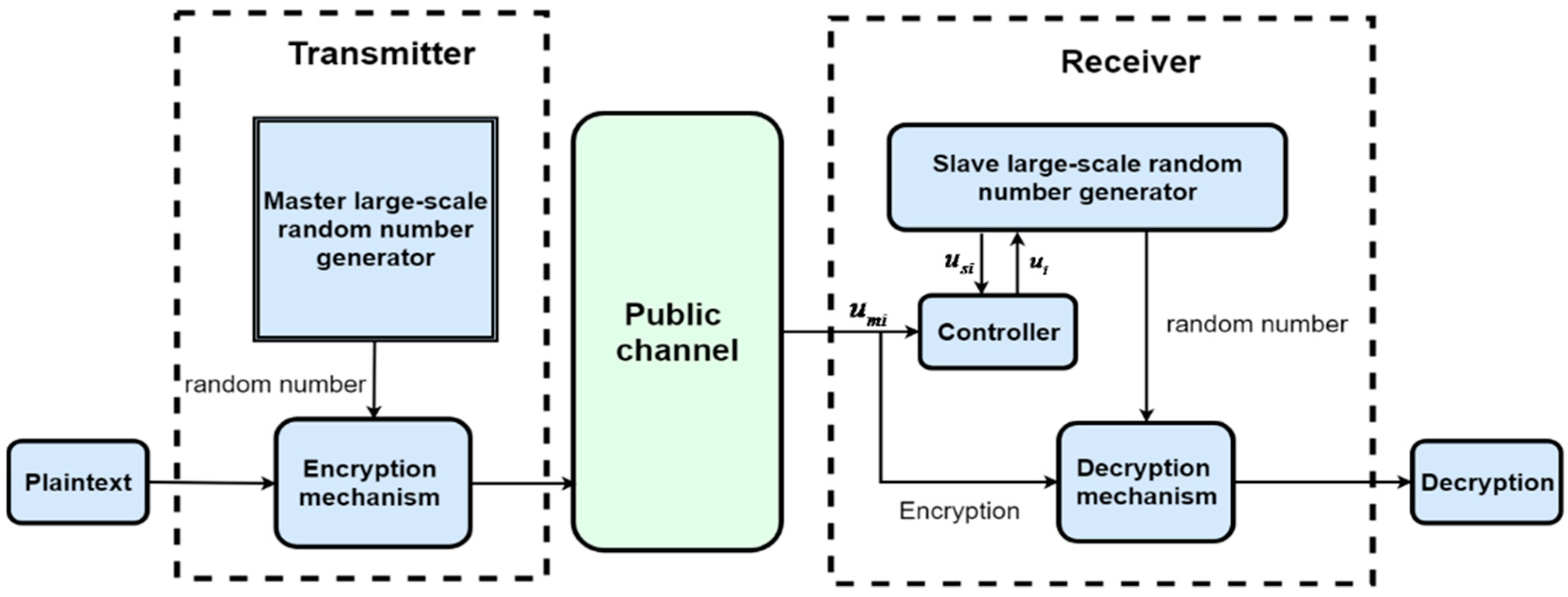
Considering the security of future applications and reducing the complexity of synchronization controller for the master-slave large-scale CRNGs, we divide the controller (12) into two parts, and satisfying , where and are the combination signals of master and slave random number generator, respectively. When the master and slave CRNGs are in different locations, only the information is sent from the master CRNG through the public channel while is generated in the slave CRNG and never appear in the insecure channel. Therefore, the synchronization controller can be composed in the slave side and the master and slave CRNGs can be synchronized without transmitting full secret information through the public channel.
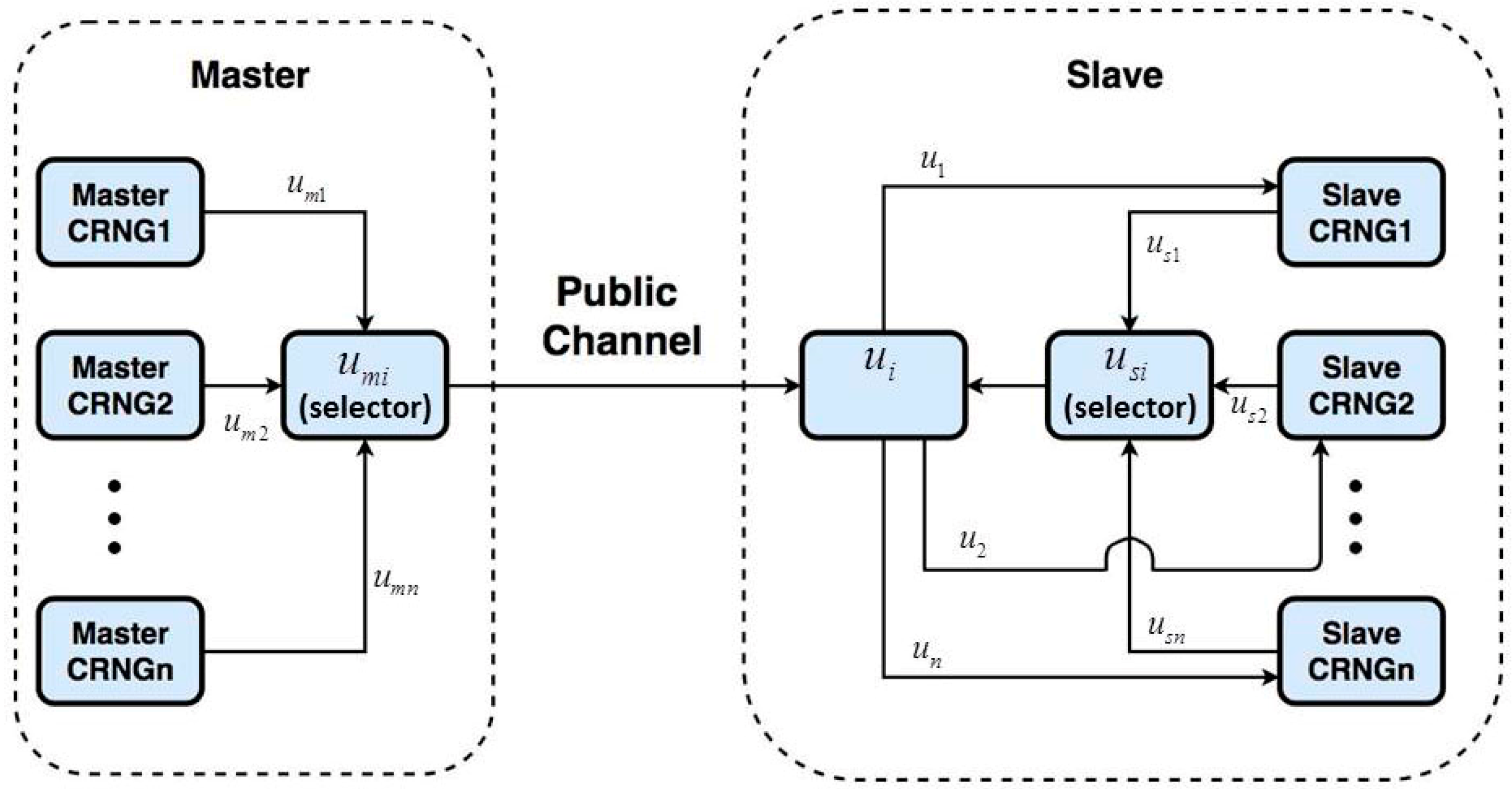
After completing the synchronization of the single master-slave CRNGs, the large-scale synchronized master-slave CRNGs is given as shown in
Figure 12.
In
Figure 12, First, the master
, sequentially generates the information
required by each
synchronization controller and in the slave
, also sequentially generates the required information
.
and
are, respectively, time-sharing selected by the selectors in the master and slave sides, then
and
is integrated to form the aforementioned controller (
) and then the synchronization between master
and slave
,
can be guaranteed. Because the computing speed of the microcontroller is extremely fast, the large-scale master-slave CRNGs can also be synchronized quickly.
4. Design of Secure Communication Based on Synchronized Large-Scale CRNGs
In the following, we will discuss how to apply the synchronized master-slave large-scale CRNGs to construct the secure communication system. The design diagram is given as follows:
In
Figure 13, the plaintext is sent to the encryption mechanism of the transmitter. The master large-scale CRNG sends the random state to the encryption mechanism and encrypt the original signal. After the encryption is completed, the transmitter transmits the cipher-text and the information
to the receiver. At the receiver, combined
with
transmitted from the transmitter, the synchronization controller
is constructed to achieve synchronization of the master and slave large-scale CRNGs. Finally, the decryption mechanism with the synchronization signal can complete the decryption.
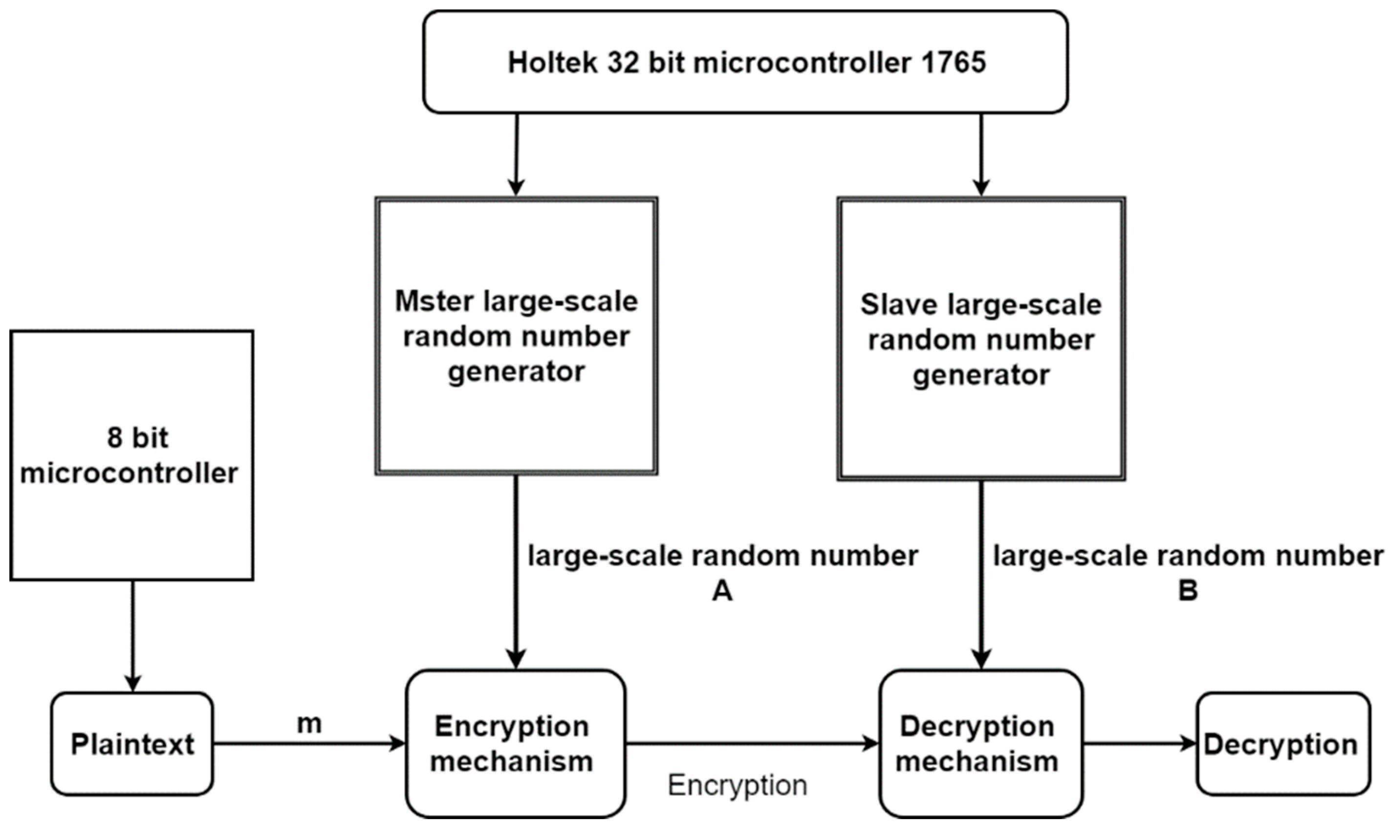
In order to verify the design of the above-mentioned secure communication system, we use Holtek’s 8-bit (HT66F50) and 32-bit (HT32F1765) microcontrollers to realize the secure communication in
Figure 13. The following
Figure 14 shows the diagram of the secure communication system. In
Figure 14, 8-bit microcontroller is used to generate plaintext and 32-bit one is used to perform large-scale CRNGs and its synchronization.
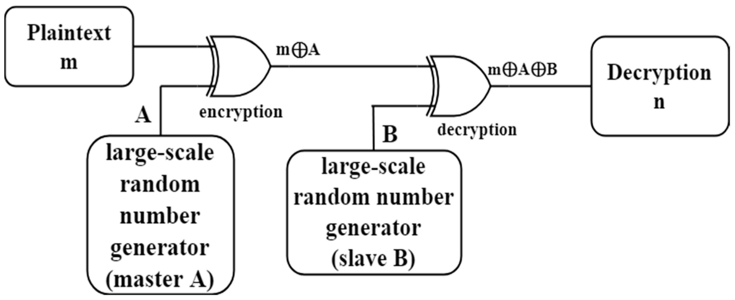
The encryption and decryption in
Figure 14 are realized by using the exclusive-or as shown in
Figure 15. When the master and slave large-scale CRNGs reaches synchronization, then the master large-scale random number A and the slave large-scale random number B will be the same. The encryption can be decrypted and the plaintext m can be recovered at the receiver side because
.
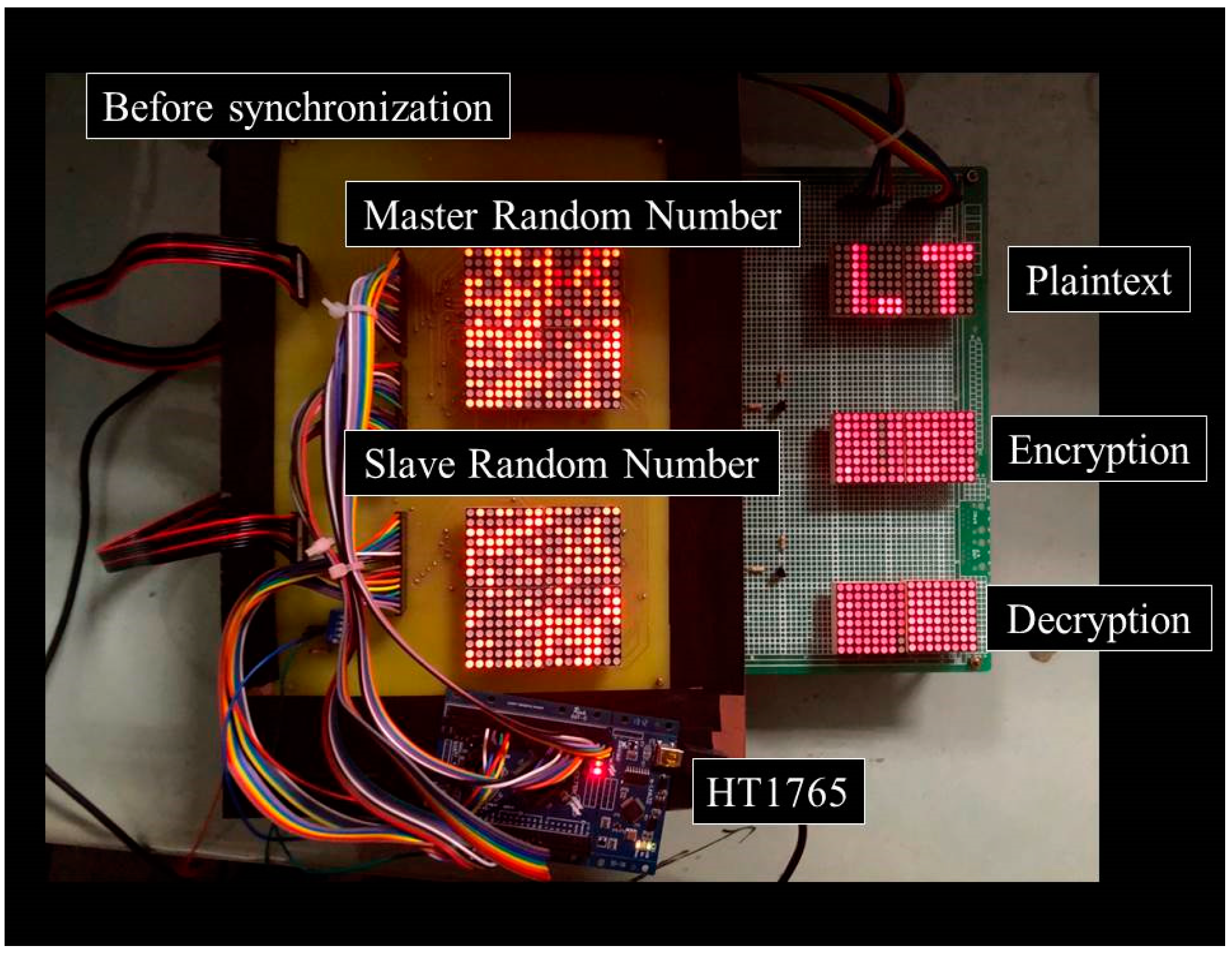
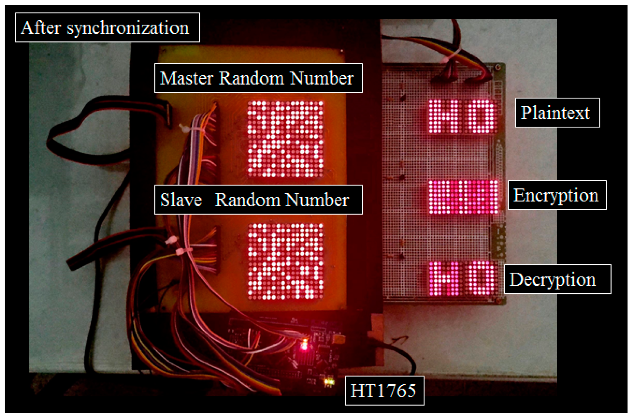
After completing the circuit design, we use some basic components to implement the circuit as shown in
Figure 16, in which the dot matrix LEDs are used to display master and slave random signals, plaintext, cipher-text and decrypted text, respectively. In
Figure 16, we first disable the synchronization controller. We can find that the master random number and the slave random number cannot be synchronized and the encryption cannot be decrypted smoothly. While in
Figure 17, we enable the synchronization controller. Therefore, it can be found that the master random number and the slave random number are synchronized, as expected and the encryption can be decrypted.


