1. Introduction
Powered exoskeletons are nowadays used in various fields, such as agriculture, and medical and welfare services [
1,
2,
3,
4]. They have a wide variety of applications in numerous fields. A powered exoskeleton in the field of rehabilitation [
5,
6,
7,
8] has low output power for safety assistance. On the other hand, the assisting power used to transport heavy baggage tends to be high [
9,
10]. Powered exoskeletons have also been developed for workers in a nuclear power plant [
11,
12]. We have also been developing a powered exoskeleton for workers who transport heavy baggage in a nuclear power plant. In case of a nuclear hazard, workers need to wear radiation-protective equipment that weighs approximately 40 kg. Moreover, the worker is supposed to carry a heavy exploration robot, such as the PackBot [
13], around in a nuclear reactor for efficient exploration. The target of our study is to develop a powered exoskeleton that is used to support workers in a nuclear plant who need to wear heavy radiation-protective equipment and carry an exploration robot.
Several approaches have been proposed to control powered exoskeletons. One is based on myoelectric signals measured by electromyography (EMG) sensors [
8,
14,
15,
16]. It estimates human intentions by measuring the action potential of the muscles, and the powered exoskeleton assists human action according to the intention. Since action potential occurs approximately 50 ms before the relevant muscle contracts, the powered exoskeleton enables rapid power assistance. However, it can easily be affected by human sweat in a hot environment. It is thus unsuitable for our intended application because workers often sweat in a radiation-protective equipment [
17]. The equipment is composed of highly airtight materials so that temperature and humidity inside the equipment are high.
Another approach is based on a force sensor/switch. Berkeley Lower Extremity Exoskeleton (BLEEX) [
18,
19,
20,
21] uses pressure sensors that measure the force between the shoe of the powered exoskeleton and the foot of the wearer to control the exoskeleton according to the configuration of the foot relative to the ground. Sano et al. [
22,
23] also proposed using force sensors attached to the bottom of the wearer’s feet to detect the pressure between the shoes of the exoskeleton and the ground. These exoskeletons control joint angle and angular velocity based on the given state of the leg, such as “stance phase” or “swing phase”, estimated by the force switches/sensors. We have examined this approach. We place a force sensor on the wearer’s back to measure the weight of the load on it. The powered exoskeleton controls itself to generate assist torque based on the floor’s reaction force. The powered exoskeleton assists the worker to carry the load according to the measured weight of the load. It has an advantage of not being affected by human sweat. However, we found that this approach cannot distinguish among similar motions, such as “walking forward” and “walking backward”. This means that the approach restricts the motion that can be assisted, and the motion needs to be designed in advance. Actually, the potential user needs to do many motions, including walking forward and backward, squat, going up and coming down stairs, run, one-leg standing, and so on. In this research, we focus on only three motions, standing upright position, walking forward, and walking backward. The motion “walking backward” is necessary because we suppose that it is hard to turn around in case that the passageway in the nuclear power plant is narrow. Furthermore, the outputs of a force sensor tend to be noisy, especially at the time of impact. Reactive assist control based on force sensors tends to be jerky due to noise. Low-pass filters can be applied but slow down the assist control. Moreover, they are likely to cause hardware trouble because of repeated impact during the walk because they are likely attached to the bottom of the foot of the powered exoskeleton.
We adopted the PLL-01 [
12], designed and developed by Activelink Co., Ltd., Japan, for our study. Its major feature is that it does not bind the legs of the wearer. It binds only the wearer’s shoulders and feet so that he/she can move his/her legs freely at the beginning of the motion because there is room to move knees due to the redundancy in the link structure of the human body, even if the joints of the exoskeleton are fixed. Other popular powered exoskeletons often bind the upper and lower legs tightly to links of the exoskeletons. Consequently, the wearer must push the exoskeleton intentionally until it estimates the motion of the wearer and begins assistance according to the estimated motion. Our powered exoskeleton enables the wearer to move his/her legs freely at the beginning of the motion, so that motion sensors on his/her legs and torso can detect motion and quickly start assistance according to the estimated motion. Liu et al. [
24] proposed a powered exoskeleton that does not bind the legs of the wearer. However, they bound lightweight, rigid bars to the wearer’s legs and measured his/her joint angles using magnetic rotary encoders. Even if the rigid bars are lightweight, they restrict the motion of the wearer. It is well known that the human joint is not a hinge joint. The center of rotation of the human joint changes during bending and extension. Therefore, rigid bars with hinge joints are not suitable for measuring human motion because they restrict human motion. Researchers have also reported motion recognition systems using nine-axis motion sensors for powered exoskeletons [
25]. Seven sensors are attached to the wearer’s trunk and legs to estimate his/her motion based on hidden semi-Markov models. Such systems can estimate the wearer’s motion; however, the only experiments on it were conducted without the user wearing a powered exoskeleton.
We propose a novel approach for power assist control of powered exoskeletons based on human motion estimation using the nine-axis motion sensors. The motion sensor can measure the wearer’s motion in a high-temperature and humid environment. Our powered exoskeleton does not bind the wearer’s legs, unlike other popular powered exoskeletons, such that he/she can move his/her legs freely at beginning of the motion. Therefore, it can quickly detect the start of walking motion. Our method estimates the wearer’s motion using a motion sensor and controls the exoskeleton based on the estimated motion. Our motion estimation and assist control are based on a motion database of the wearer and the powered exoskeleton. The database consists of sequential output data from the motion sensors attached to the wearer and the joint angles at the waist and knees of the powered exoskeleton during specific motions. An advantage of the proposed method is that it can recognize several motions of the wearer that are challenging for other similar methods. Another advantage is its low cost. Motion sensors are cheaper than commercially available load cells and are robust such that they avoid repeated impact during a walk because they are attached to the wearer’s limbs. A force sensor or force switch embedded into the bottom of the foot can be easily broken because of the direct impact with the floor during the walk. This paper shows the effectiveness of the proposed method through experiments with a powered exoskeleton.
2. Powered Exoskeleton without Binding Legs
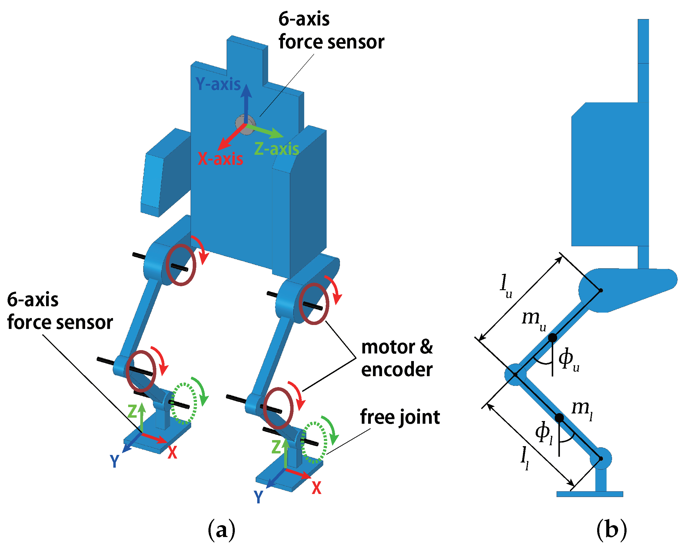
Figure 1 and
Figure 2 show the powered exoskeleton, designed and developed by Activelink Co., Ltd., Nara City, Japan [
12], used in this research. It consisted of four geared motors and rotary encoders at the knee and hip joints. Their joint angles were controlled by PID controllers. There was no motor at the ankle joints. The degrees of freedom of the joints are shown in
Figure 1a. The powered exoskeleton bound a wearer only at his/her shoulders and feet. There was no binding at the limbs of the upper and lower legs, as in conventional powered exoskeletons. The wearer could move his/her knees freely, especially at the beginning of the motion. The powered exoskeleton was designed to have comparatively small torque, at most 50 Nm, at each joint so that the back-drivability ensured safety in case of loss of control. Therefore, the powered exoskeleton was not designed to support all loads on the wearer, but only part of it.
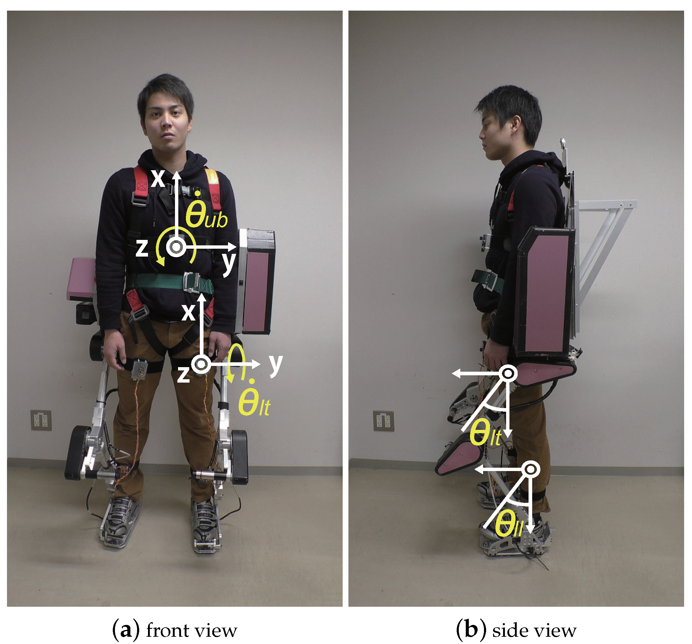
Figure 2 shows a wearer attaching five nine-axis motion sensors as well as their positions and coordinates. The x-axis was upward, the y-axis was horizontal, and the z-axis was in the forward direction. The wearer attached them to the chest and the upper and lower legs. The powered exoskeleton can distinguish the motions “walking forward” and “walking backward” based on the outputs of the motion sensors. The algorithm proposed by Sebastian Madgwick [
26] was adopted to calculate the posture of the motion sensor in this paper. This method used acceleration, angular velocity, and geomagnetism measured by the motion sensors to calculate posture. Three force sensors were attached to the powered exoskeleton. One was on the back, and the others were on the feet.
Figure 3 shows the shoe designed for the wearer, the foot of the powered exoskeleton, and the force sensor attached to both. The force sensor on the back measured the load on the shoulder of the wearer. The force sensors on the feet measured the interactive force between the feet of the wearer and those of the exoskeleton. The axes of force sensors are depicted in
Figure 1a. These sensors measured load and moment along the three directions. The force sensors were used only for the evaluation of our proposed method.
3. Leg Control Based on Human Motion Prediction Using Motion Sensor
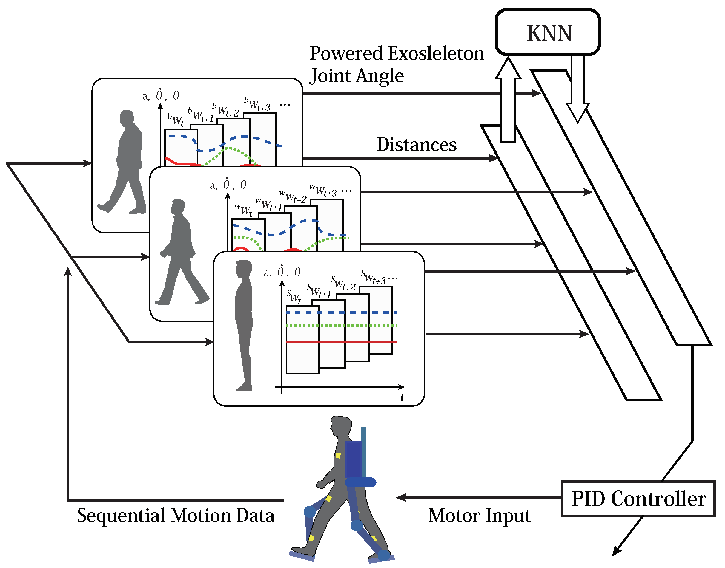
Figure 4 shows the overview of the proposed controller using motion sensors for our powered exoskeleton. The powered exoskeleton recognizes the wearer’s motion to assist him/her. It estimates in advance by a few hundred milliseconds the future joint angles of the powered exoskeleton according to the recognized motion to assist the wearer in real time. The motion estimation and the calculation of the desired joint angles of the powered exoskeleton are based on a motion database compiled in advance. This database is composed of sequential data of the wearer’s motion, the label of the motion, and the corresponding leg motion of the powered exoskeleton. The joint angles of the legs of the powered exoskeleton are controlled to be estimated based on the database by PID controllers.
The database includes sequential data from motion sensor attached to the wearer as feature vectors, each with motion class label “standing”, “walking forward”, or “walking backward”, and the joint angles of the powered exoskeleton as the wearer exhibited the relevant motion. The data of the motion sensors are angles , angular velocities , and acceleration rates . Indices , , , , and indicate the upper-right leg, the lower-right leg, the upper-left leg, the lower-left leg, and the torso, respectively. The joint angle of the powered exoskeleton is defined as . Indices , , , and indicate the right hip, the right knee, the left hip, and the left knee of the powered exoskeleton, respectively.
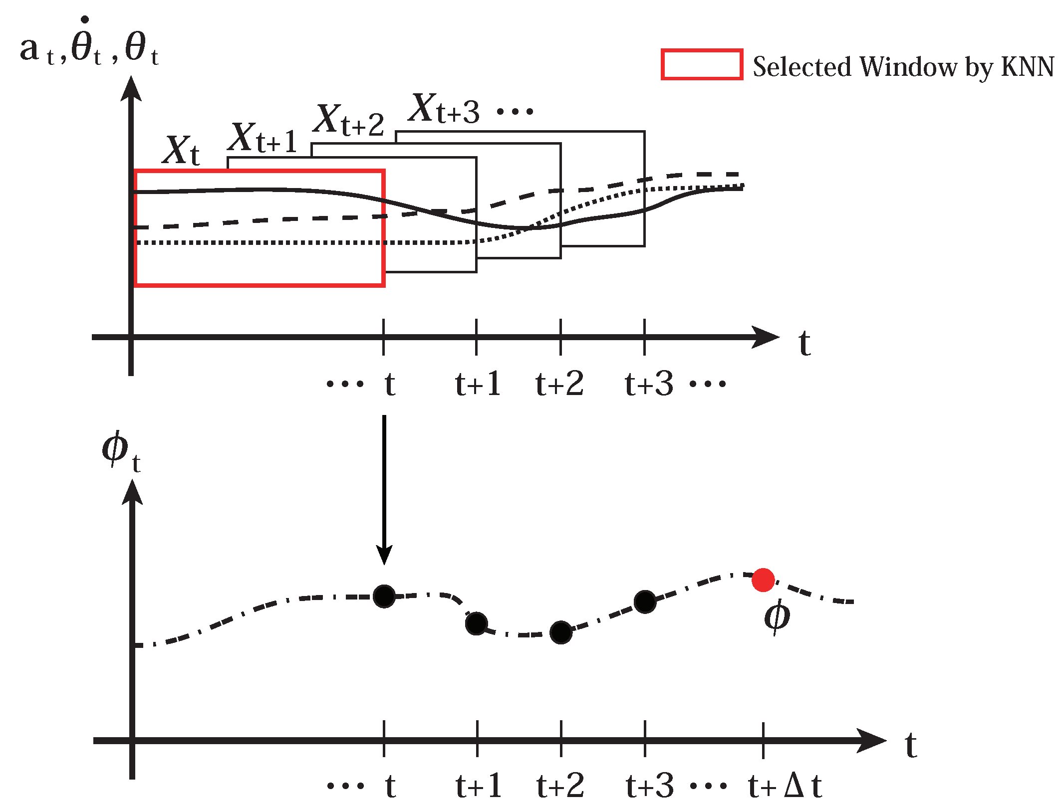
The wearer’s motion dataset is defined by piecewise sequences of , where t is the time index. Sequential motion data are segmented using a window of size m into sequence data . The sequence dataset is assigned one of the three motion category indices of “standing” , “walking forward” , and “walking backward” . It is also assigned the joint angles of the powered exoskeleton at time , . A dataset in the motion database is composed of the wearer’s motion dataset, the motion category, and the joint angles of the powered exoskeleton, , where is one of , , and . The database D is composed of the set of datasets .
The powered exoskeleton recognizes the wearer’s motion using the k-nearest neighbors method on the database
D. We choose the k-nearest neighbors algorithm because it is one of the non-parametric methods that do not make some specific assumption about the motion of the human or the powered exoskeleton and it is the simplest algorithm and works in real time for our application. Motion data of the wearer at time
t are defined as
. Query sequential data with window size
m are defined as
. They calculate the normalized Euclidean distance
between
and
, where
i is the data index in database
D. It chooses
k datasets from the database
D with the smallest distances based on a normalized
, and collects the set of motion category IDs
, each of which is one of the motion categories
,
, and
. Then, the k-nearest neighbor algorithm outputs most of the motion category in
. The term “majority” indicates the motion category with the maximum number of category indices in the nearest neighbor set of the motion category indices
c. For example, if the number of the nearest datasets with the motion category index
is higher than that of datasets with motion category indices
and
,
is said to be in the majority. The normalized distance
is calculated as below:
where
indicates the transpose and
is a variance matrix with variance vector
on the diagonal. The variance vector
is the vector whose components are the variances of the corresponding components of
, which used for database
D.
It estimates the appropriate joint angles of the powered exoskeleton at time
,
, according to the estimated motion of the wearer based on the k-nearest neighbor algorithm. For example, if the estimated motion is “standing”, it chooses only the datasets whose motion categories
is
for the estimation of
. An overview of the estimation of the appropriate joint angles
is provided in
Figure 5 and the algorithm is shown in Algorithm 1. The input to the joint motor
is calculated by Equation (
2):
where
is the desired joint angle and
is the actual joint angle of the powered exoskeleton at time
t.
,
, and
are the proportional, integral, and differential gains, respectively.
| Algorithm 1 Wearer’s motion estimation, and calculation of joint angle of powered exoskeleton |
load database acquire sequential motion data of the wearer : components of is , or if majority of is then recognizes the current motion as “standing” motion : end if if majority of is then recognizes the “walking forward” motion : end if if majority of is then recognizes the “walking backward” motion : end if return
|
5. Experiments
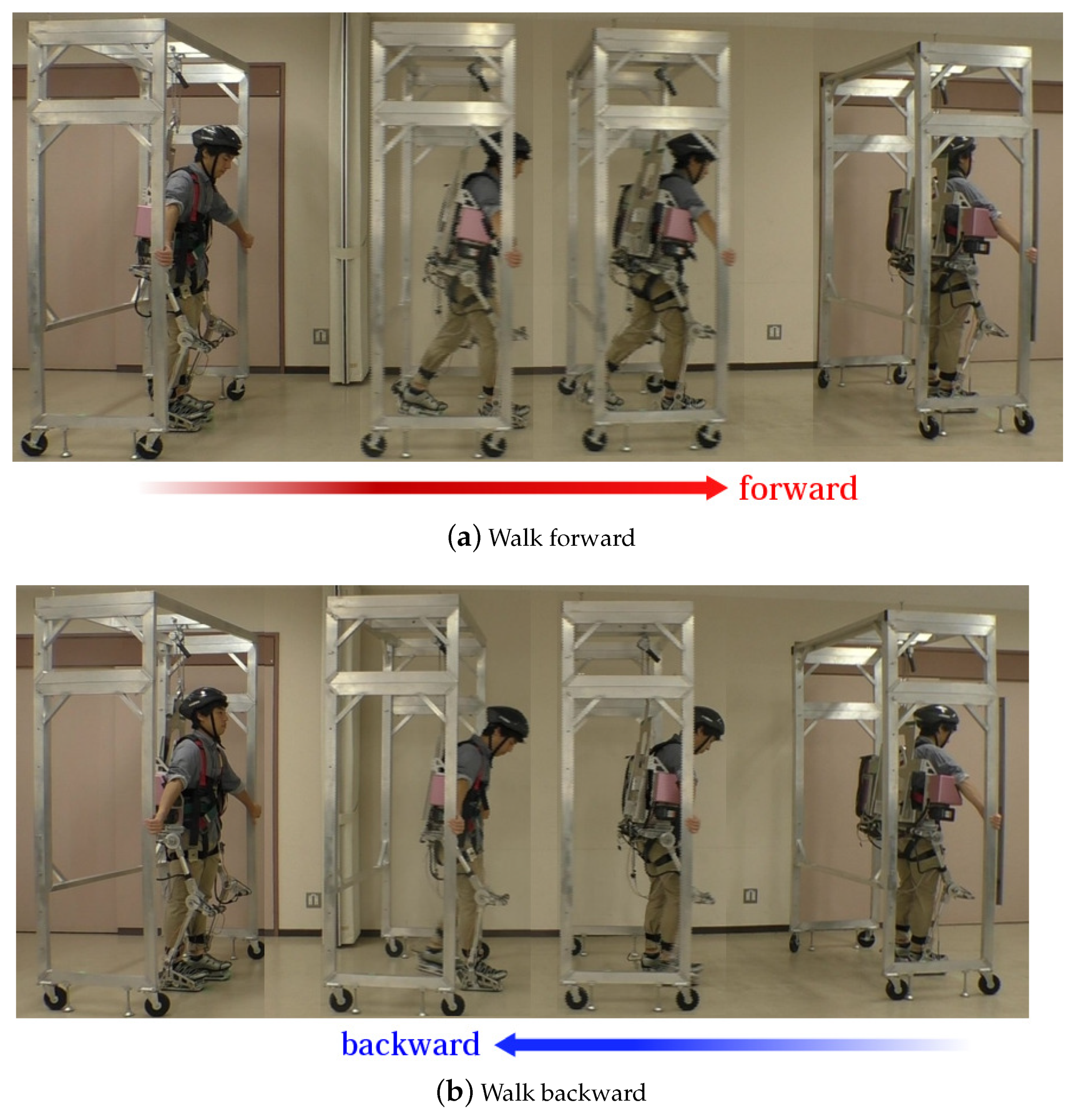
Experiments were conducted to test the proposed method by comparing it with two comparative methods (The experiments were approved as No. H2016001 by the Research Ethics Committee, Department of Human and Artificial Intelligent Systems, Graduate School of Engineering, University of Fukui.). One wearer was a male student in his early 20s. In this experiment, he walked forward and backward for approximately 5 m wearing the powered exoskeleton. The data for the database were obtained while the powered exoskeleton was lifted by a gantry, and the wearer walked with the gantry so that he did not have any payload from the powered exoskeleton while his motion was restricted by the kinematics of the exoskeleton.
Figure 6 shows how the data for the database were obtained for (a) “walking forward” and (b) “walking backward”. The datasets for “standing” were also obtained when the wearer stood in upright position. The sampling time was approximately 80 milliseconds. The window size of the dataset was 10 steps. The number of datasets for each motion category was approximately 50.
Once the database had been constructed, the proposed method was applied. The k of the k-NN was set to 5 for motion category recognition and 10 for appropriate joint angle estimation in the experiments.
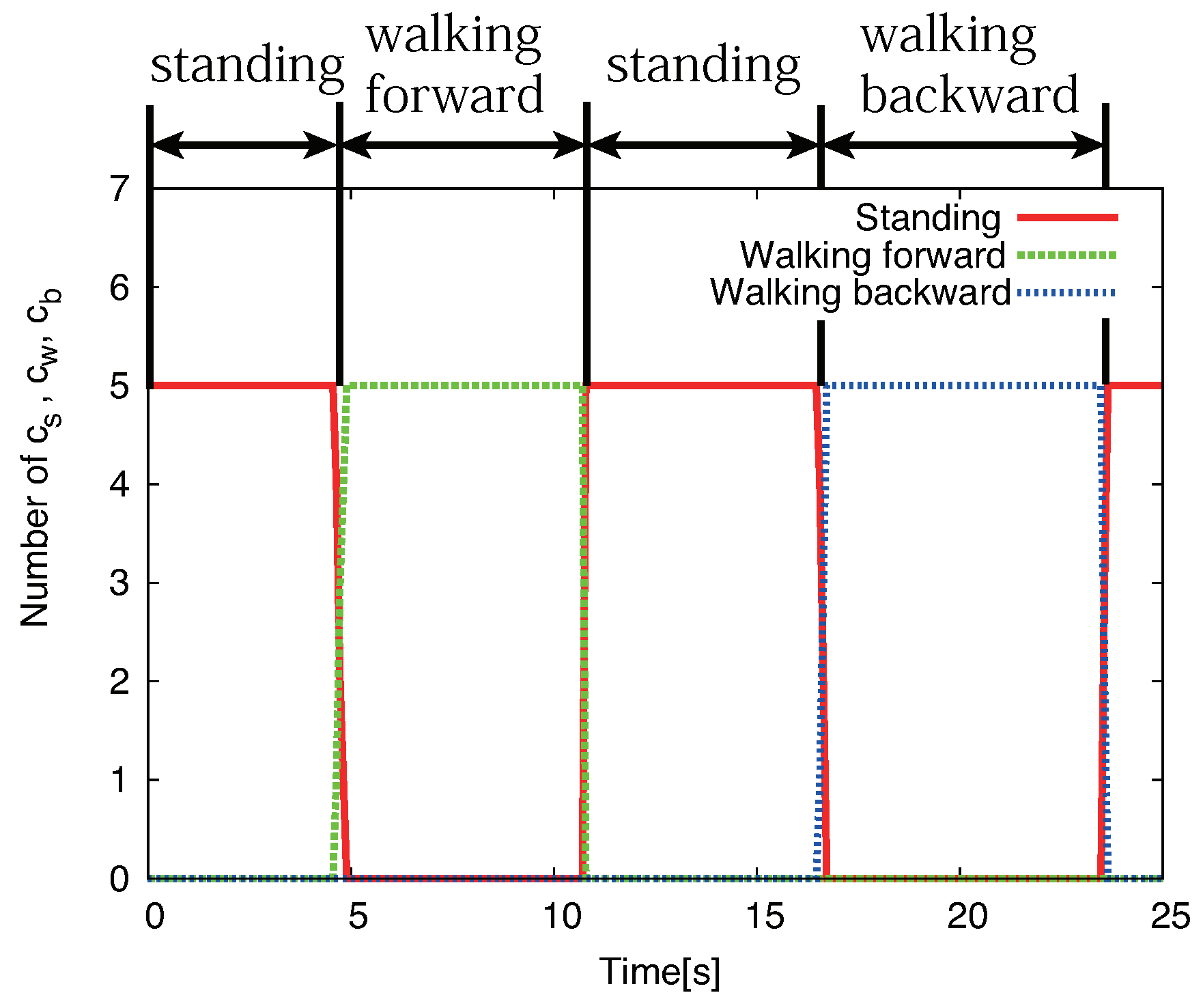
Figure 7 shows the results of the estimation of the wearer’s motion based on the proposed method. The wearer first stood in the upright position, started walking forward, stopped, and stayed still there for a while; he then walked backward, and stopped. The figure shows that the proposed method successfully recognized the wearer’s motion. The sampling time of the control system was approximately 80 milliseconds. The calculation of the motion recognition takes only about 20 milliseconds on the controller. The calculation of the whole control system including sensor value acquisition and motor control takes less than 80 milliseconds so that the powered exoskeleton assists the wearer’s motion in real time.
An additional 15 kg weight was placed on the powered exoskeleton in the experiments. The proposed method and the competitive methods described in
Section 4.1 and
Section 4.2 were applied to the powered exoskeleton one by one across enough breaks for the wearer.
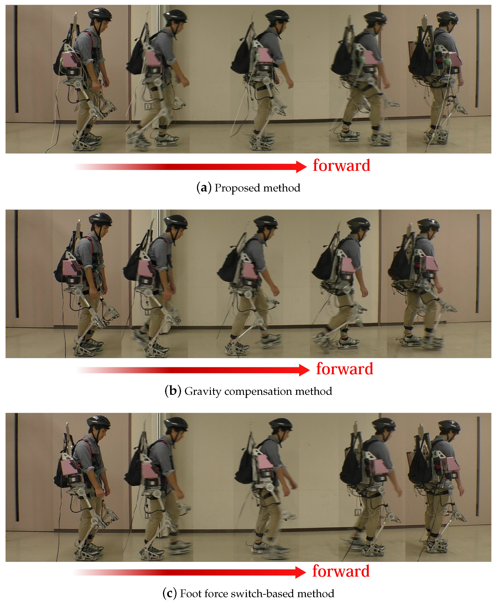
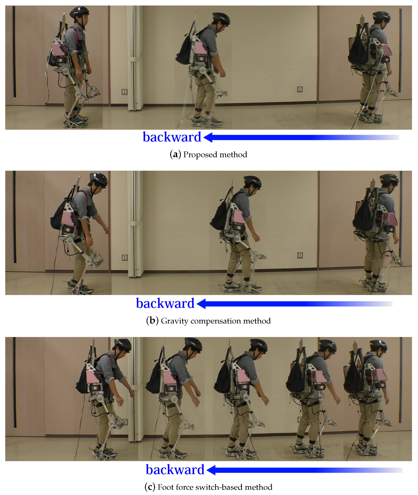
Figure 8 and
Figure 9 show the image sequences of the motion “walking forward” and “walking backward” based on each method. The images were captured from a side. The motion category recognition worked perfectly based on the proposed method and the foot force switch-based method.
Table 1 shows the walking speeds for “walking forward” and “walking backward” based on each method.
Figure 8 shows that the proposed method and the foot force switch-based method enabled the wearer to walk smoothly while the gravity compensation-based method did not. The sampling time of image capture was approximately 1.8 s. The gravity compensation-based method caused the wearer to walk more slowly than the other methods.
Table 1 also shows that the proposed and the force switch-based methods supported “walking forward”. The wearer supported by the gravity compensation method slowly walked forward because this method does not actively support walking.
Figure 9 shows that the proposed method allowed the wearer to walk backward faster than other methods. The proposed method recognized the wearer’s motion of walking backward correctly and supported it appropriately. On the other hand, the foot force switch-based method caused the wearer to walk backward slowly because it tried to support him in walking forward even though he was walking backward. Eventually, the wearer needed to exert a strong force to push his leg backward and walk slowly. It was difficult for the foot force switch-based method to recognize walking forward and backward based only on the outputs of the force sensors of the feet. This was one of the drawbacks of the method. The gravity compensation method showed good result, but the walk tended to be slow because it did not assist the horizontal motion of the leg, even though it assisted vertical leg motion, such that the wearer had to firmly push his leg back.
Table 1 supports the analysis in terms of the walking speed for the motion “walking backward”.
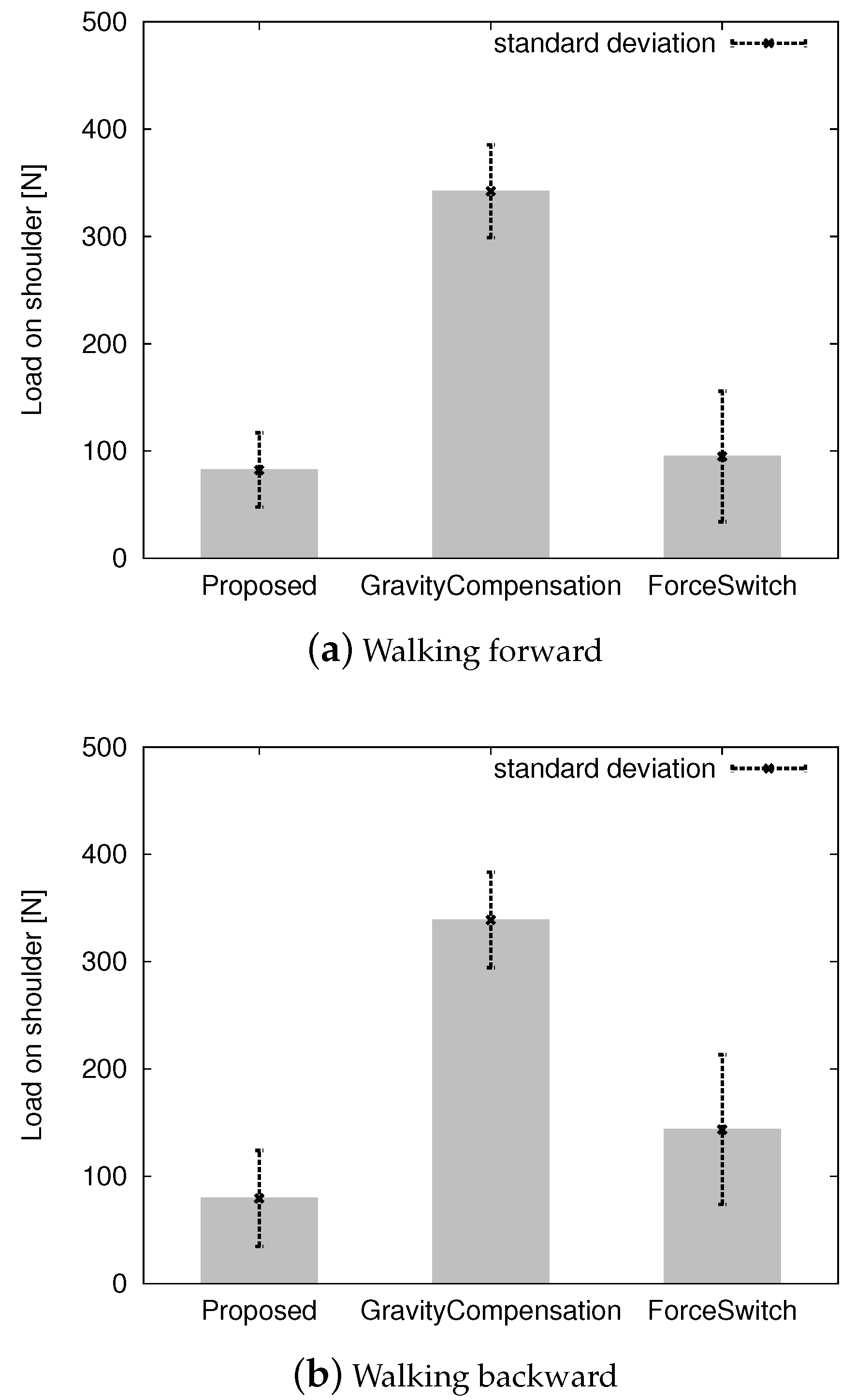
Figure 10 shows the average load on the wearer’s shoulder while walking forward and backward. The proposed method and the foot force switch method maintained a load of approximately 100 N whereas the gravity compensation method maintained one of 350 N. If there was no assist control, the wearer had approximately 350 N on his shoulders. The proposed method successfully reduced the load. It depends on the motion database
D. When the datasets for the database were sampled, the powered exoskeleton was hung up on the gantry so that the wearer had no load due to the exoskeleton. Therefore, the proposed method lifted the exoskeleton. To maintain the back-drivability of the powered exoskeleton, we kept the control gain as small as possible. An approximately 100 N load on the shoulder was imposed because of the small control gain for back-drivability. The gravity compensation method did not reduce the load on the wearer’s shoulder. If the control gains
and
in Equations (
3) and (4) became large, the load on the wearer’s shoulder in the upright position became small, but it became challenging for the wearer to swing the leg because the powered exoskeleton tried to keep the leg as vertical as possible. It eventually lost back-drivability. To retain back-drivability, the control gains
and
needed to be small, in which case the system failed to reduce the load on the wearer’s shoulder. The foot force switch-based method was as good as the proposed method according to
Figure 10.
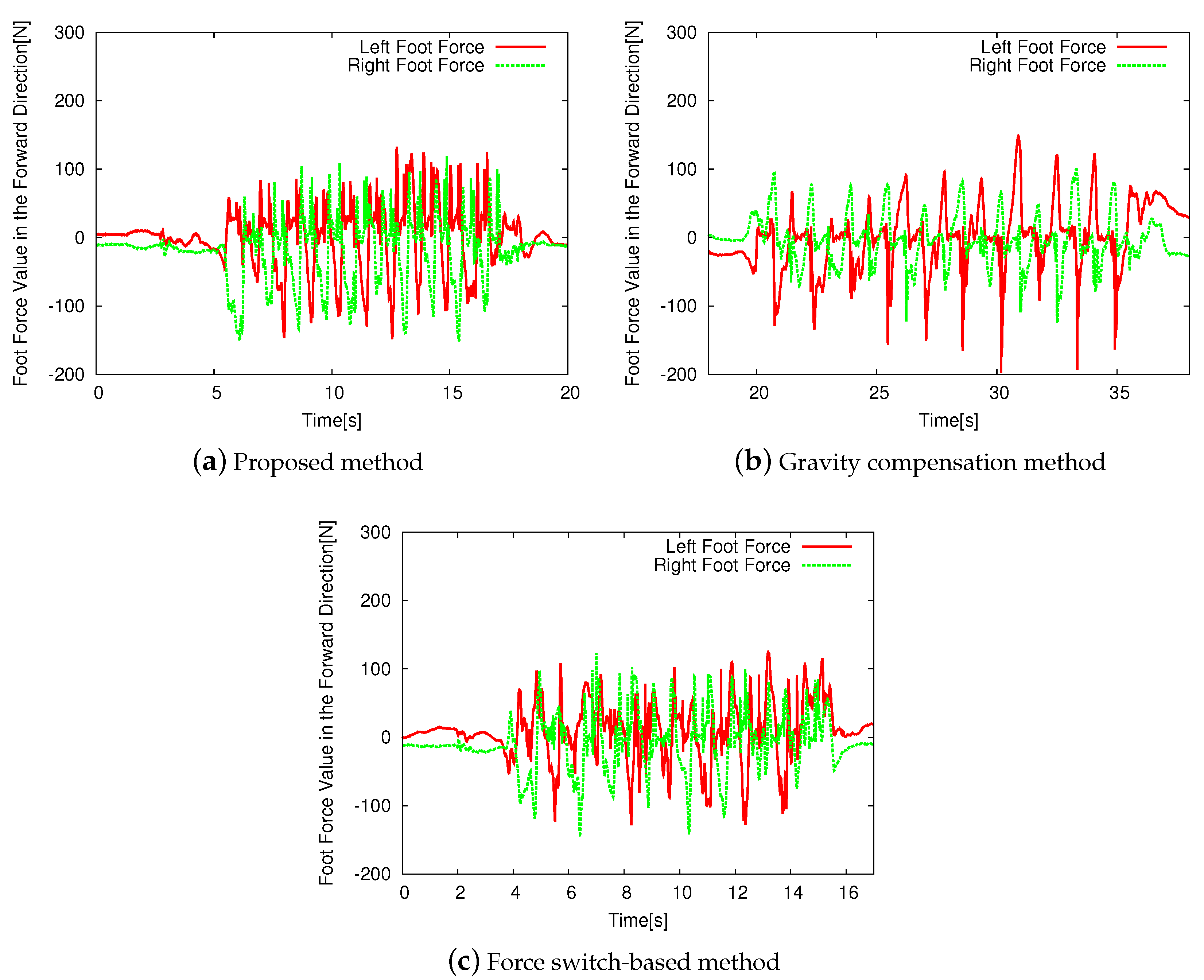
Figure 11 shows the horizontal front-back reaction force measured by foot force sensors while the wearer walked based on each control method. The reaction forces on the left leg under the proposed method and the force switch-based method were smaller than that for the gravity compensation method. This was because the gravity compensation method did not consider the motion of the feet in the horizontal direction. The proposed method used motion sensors to predict the posture of the powered exoskeleton and successfully reduced the reaction forces on the feet in the horizontal direction. The force switch-based method also reduced the reaction forces because the pre-defined motion for the method fed the swinging leg forward and the standing leg backward. The reaction force on the right leg was comparatively small when the gravity compensation was applied because of the wearer’s gait.
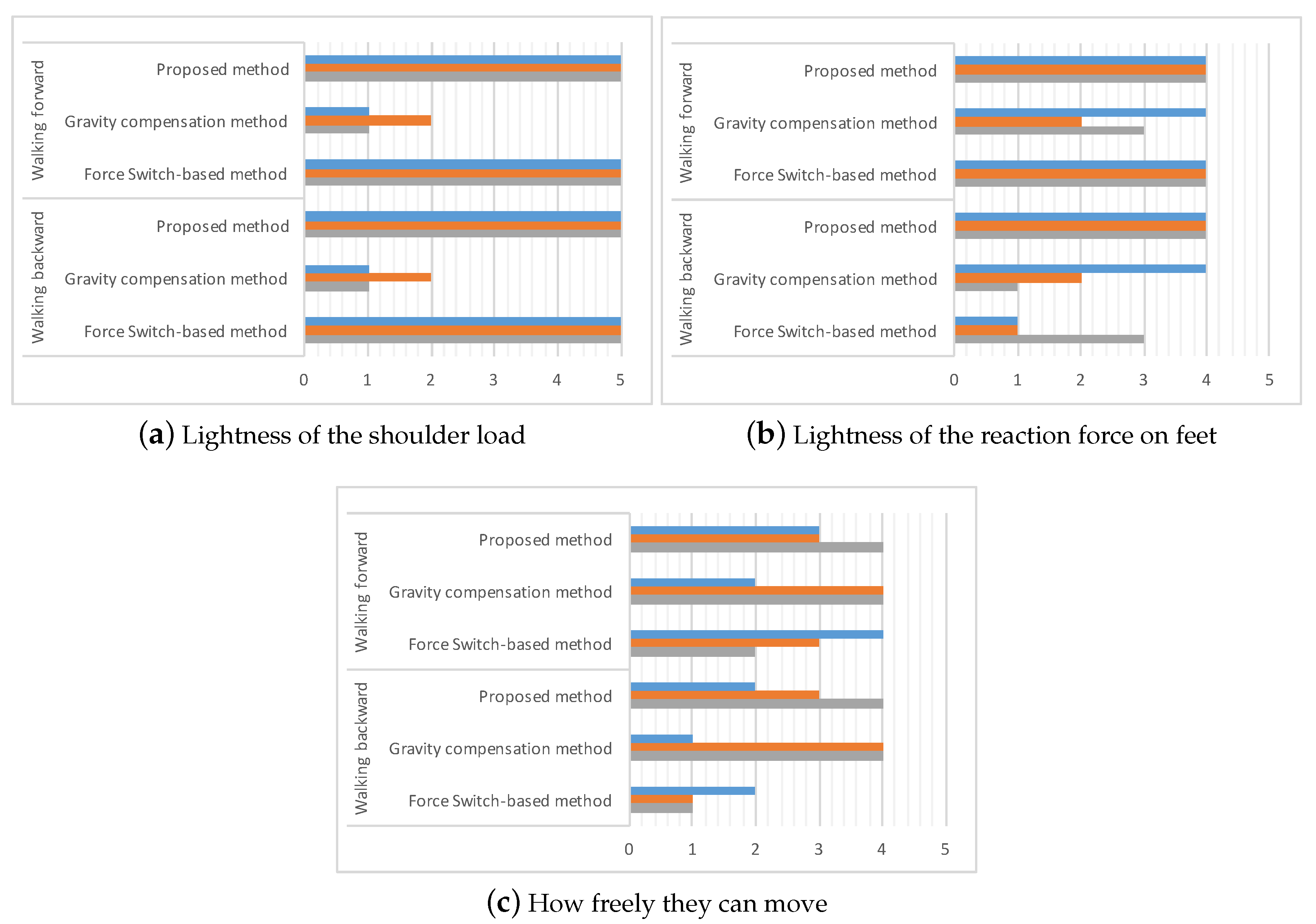
Figure 12 shows the horizontal front-back force measured by the foot force sensors while the wearer walked backward based on each control method. The proposed method showed the smallest magnitudes of forces during this. This was because it appropriately recognized the wearer’s motion and controlled the legs of the powered exoskeleton based on the estimated motion. The gravity compensation method yielded the highest resistance force to the wearer’s legs because it did not consider the motion of the feet in the horizontal direction, as mentioned above. The force switch-based method failed to support backward walking because it could not distinguish between walking forward and backward, and the pre-defined motion for the method was designed for forward walking. Eventually, the wearer had to push the swinging leg more strongly. The reaction force on the right foot was small because of the manner of the wearer’s walk.
Figure 11 and
Figure 12 show that there are differences of the gate frequencies of the walks. The wearer with the gravity compensation method (b) walks slower than the other methods (a) and (c). The wearer with the gravity compensation method (b) needs to push the powered exoskeleton forward and backward by his legs intentionally because the gravity compensation method (b) just compensates for the gravity effect of the powered exoskeleton and does not support the current human motion. On the other hand, the proposed method (a) and the force switch-based method (c) support the walk motion actively so that the wearer can walk faster.
Figure 11 and
Figure 12 show that there were differences in the gate frequencies of the walks. The wearer using the gravity compensation method (b) walked slower than with methods (a) and (c). The wearer using the gravity compensation method (b) needed to push the powered exoskeleton forward and backward using his legs because this method (b) only compensates for the effect of gravity due to the powered exoskeleton and does not support the human motion. On the other hand, the proposed method (a) and the force switch-based method (c) supported the walking motion actively such that the wearer could walk faster.
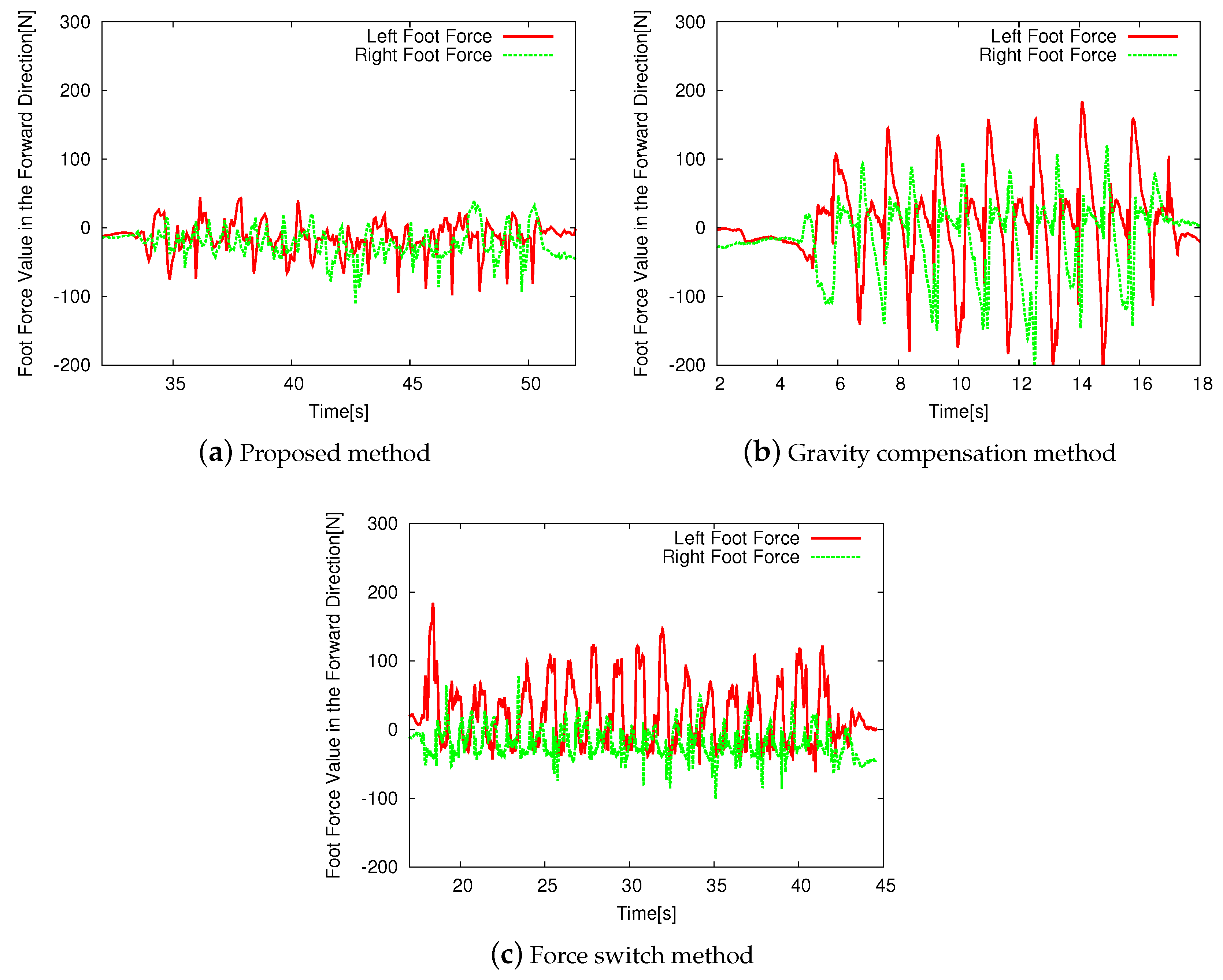
To evaluate the usability of the proposed powered exoskeleton, we had a questionnaire on the powered exoskeleton controlled by each method. Three users wore the powered exoskeleton controlled by each method, the proposed method, the gravity compensation method, and the force switch method. After they walked forward, stopped, and walked backward, and repeated them a few times, they answered the questions on the lightness of the shoulder load, lightness of the reaction force to feet, and how freely they could move. The users answered these questions with numbers from 1 to 5; 1 is for the lowest and the 5 is the highest.
Figure 13 shows the results of the questionnaire. According to
Figure 13a, they were aware of the lightness of the shoulder load if the proposed and the force switch methods applied. The gravity compensation method failed to reduce the shoulder load. The answers are consistent with the discussions on
Figure 10.
Figure 13b suggests that the proposed and force switch methods successfully support the feet of the users when they walk forward but the force switch method failed to support them when they walk backward. The evaluation of the gravity compensation method depends on the user’s preference. This result is also consistent with the discussion on
Figure 11 and
Figure 12.
The gravity compensation method received high scores on how freely they can move according to the
Figure 13c. The reason is that the gravity compensation method does not assist the power actively and just follows the motion of the user while the other methods try to assist the motion actively, but the assistant becomes against the user’s intention occasionally. The force switch method has a low evaluation from the users especially when they walk backward. The reason is that the method was designed for walking forward.
Figure 13 indicates that the overall evaluation of the proposed method is better than the other while it has room to improve the power assistant abilities. It is one of the future works to improve them.
The experimental results show that the proposed method outperformed the other competitive methods comprehensively, as it enabled the wearer to walk faster with a smaller reaction force than the other methods.
6. Conclusions and Discussions
This study proposed a power assist control system based on the wearer’s estimated motion using motion sensors for a powered exoskeleton without leg binding. It recognizes the wearer’s motion using motion sensors, estimates appropriate joint angles for the powered exoskeleton based on a motion database compiled in advance, and assists the wearer’s motion in real time. The experimental results exhibited the effectiveness of the proposed assistive system.
The major feature of our powered exoskeleton is that it does not bind the legs of the wearer. It allows the wearer to move his/her legs freely at the beginning of the motion even if the joints of the exoskeleton are fixed because of the room to move knees. The feature enables us to use motion sensors to recognize the wearer’s motion and give feedback on the power assist. It supports only hip and knee joints rotating on the lateral direction. The other joints, for example, hip joints rotating in different directions and ankle joints are passive. The wearer needs power assists on those joints, too, if the load on the wearer increases more. It is one of the future works from the viewpoint of the mechanical design of the powered exoskeleton to strengthen the existing active joints and replace the passive joints to the active one.
In principle, the proposed method simply replays the pre-recorded joint angles from the database. However, even if the walking speed changes, it tries to find the best matching motion from the database to support it. If the wearer walks more slowly than the pre-recorded walk, the system tries to find the best matching phase of the walk and assists faster walking. If the wearer walks more quickly than the pre-recorded walk, it assists in walking slower but does not prevent the human walk because it always follows the walk to find the best matching phase based on the database. Therefore, it can adapt to a certain degree. If the walk is too far from the pre-recorded datasets, the proposed method fails to support it and needs a new dataset for walks at different speeds. This will form part of our future work.
In this paper, we employed the k-nearest neighbors algorithm to deal with the motion database. The reason is that it does not make some specific assumptions on the motions of the human or powered exoskeleton and it is the simplest method among the various machine learning technique. However, there is a possibility to employ the other sophisticated algorithm. We are investigating more effective algorithms for motion learning [
27,
28]. Another part of our future work in this area will involve increasing the variety of motions that can be assisted, that is, not only standing and walking motions and forward-backward motions, but also sideways walking, squatting, swinging the body, climbing stairs, and so on. We also intend to investigate online updates of the motion database.


