Article

Algorithm for Base Action Set Generation Focusing on Undiscovered Sensor Values

1
Department of Computer Science, Kitami Institute of Technology, 165 Koencho, Kitami, Hokkaido 090-8507, Japan
2
Department of Complex and Intelligent Systems, Future university hakodate, 116-2, Kameda-Nakanocho, Hakodate 041-8655, Japan
*
Author to whom correspondence should be addressed.
Appl. Sci. 2019, 9(1), 161; https://doi.org/10.3390/app9010161
Submission received: 26 November 2018 / Revised: 27 December 2018 / Accepted: 29 December 2018 / Published: 4 January 2019
(This article belongs to the Special Issue Advanced Mobile Robotics)

Abstract

:
Previous machine learning algorithms use a given base action set designed by hand or enable locomotion for a complicated task through trial and error processes with a sophisticated reward function. These generated actions are designed for a specific task, which makes it difficult to apply them to other tasks. This paper proposes an algorithm to obtain a base action set that does not depend on specific tasks and that is usable universally. The proposed algorithm enables as much interoperability among multiple tasks and machine learning methods as possible. A base action set that effectively changes the external environment was chosen as a candidate. The algorithm obtains this base action set on the basis of the hypothesis that an action to effectively change the external environment can be found by observing events to find undiscovered sensor values. The process of obtaining a base action set was validated through a simulation experiment with a differential wheeled robot.

1. Introduction

Previous machine learning algorithms [1,2] such as Q-learning use a given base action set and choose an action from the set repeatedly [3,4,5,6,7]. Pre-defined action sets are commonly used in reinforcement learning, where a robot will choose one action from the set and then use it to execute one action. An action sequence of the robot is generated by repeating this cycle [8,9]. Conventional reinforcement learning methods use a pre-defined action set or acquire actions that depend on the specific task through trial and error processes. Pre-defined actions are designed by hand and there is no clear evidence that these actions are the optimal ones for robots.
Neural networks have been used to obtain actions for achieving specific tasks [10,11,12]. With this approach, neural networks are given an evaluation function and they decide actions in accordance with this function when a correct teacher signal is unknown. A base action set is also given in such cases.
The base action set and their elements are designed by hand. However, many actuators are used in constructing robots, so its possible actions can become more complicated, which makes it difficult to determine and split ino a suitable number of actions. For these reasons, we propose an algorithm to obtain an action set suitable for the external environment and the robot body. The proposed algorithm obtains a base action set that does not depend on specific tasks and is usable universally. It enables as much interoperability among multiple tasks and machine learning methods as possible and obtains a base action set that effectively changes the external environment.
Many methods to enable locomotion for a complicated task through trial and error processes using reinforcement learning have been proposed [13,14,15,16,17,18,19]. Also, a modular self-reconfigurable robot that learns actions for its current configuration and a specific task using multi-agent reinforcement learning method has been reported [20]. The reward function required sophisticated design and acquired actions were only for the specific tasks in these cases, so the aims of this study to get a universal base action set were different.
Although some deep learning methods for complicated tasks have been reported in recent years, the fundamental mechanisms underlying them, such as neural networks and reinforcement learning methods, are still the same. Specifically, these behaviors use a pre-defined action set or acquire actions depending only on specific tasks [21,22,23].
Emotional behavior generation has also been effective in variation of robot action [24,25,26,27]. Several studies have demonstrated richness in variation and mutually independent actions corresponding to human responses. However, they focused on emotional behavior and not on generating effective actions to change the external environment.
The purpose of our research is to develop an action generation algorithm that does not depend on the specific task and to clarify the characteristics of the parameters used in the algorithm. Also, we identify which parameter values are suitable for robot action generation before applying the proposed algorithm to a real robot.
We hypothesize that an action to effectively change the external environment can be found by observing events to find undiscovered sensor values. Thus, we developed an algorithm to obtain a base action set to change the external environment capably.

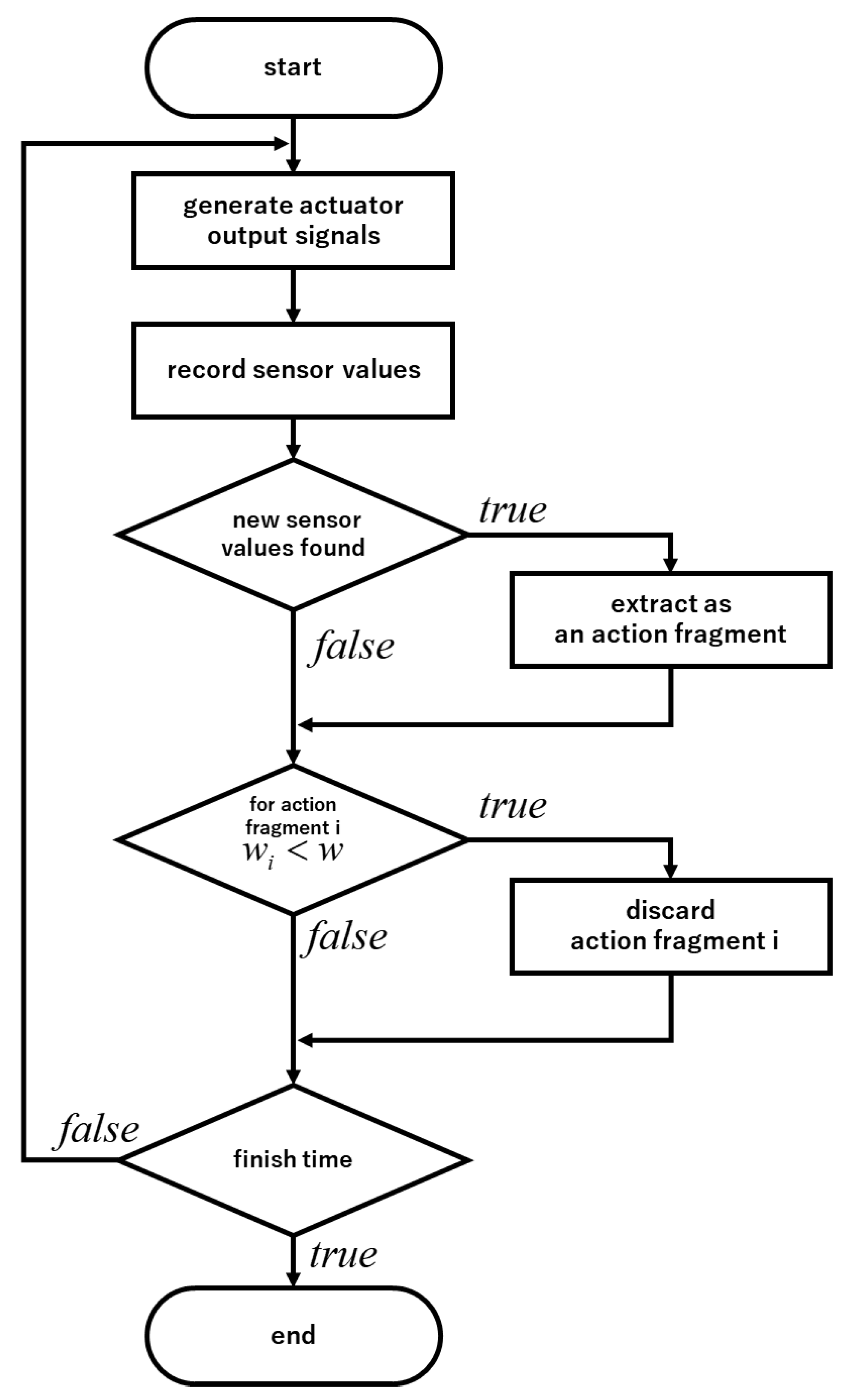
2. Base Action Set Generation Algorithm Focusing on Undiscovered Sensor Values

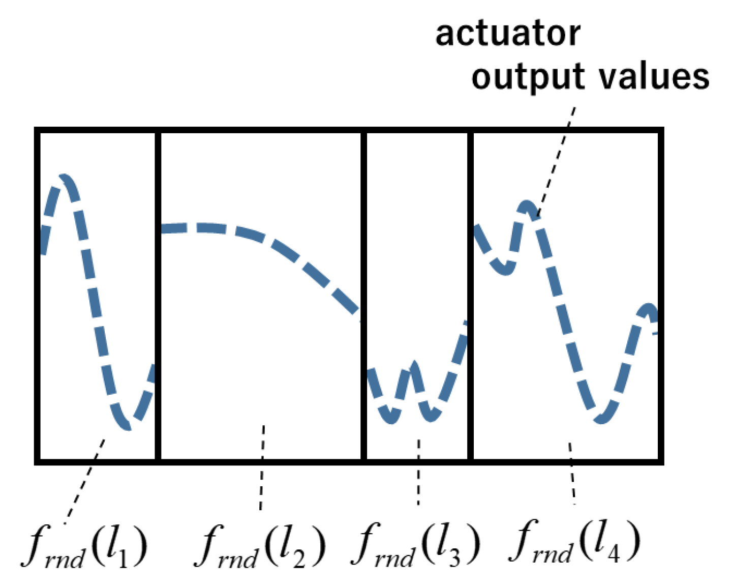
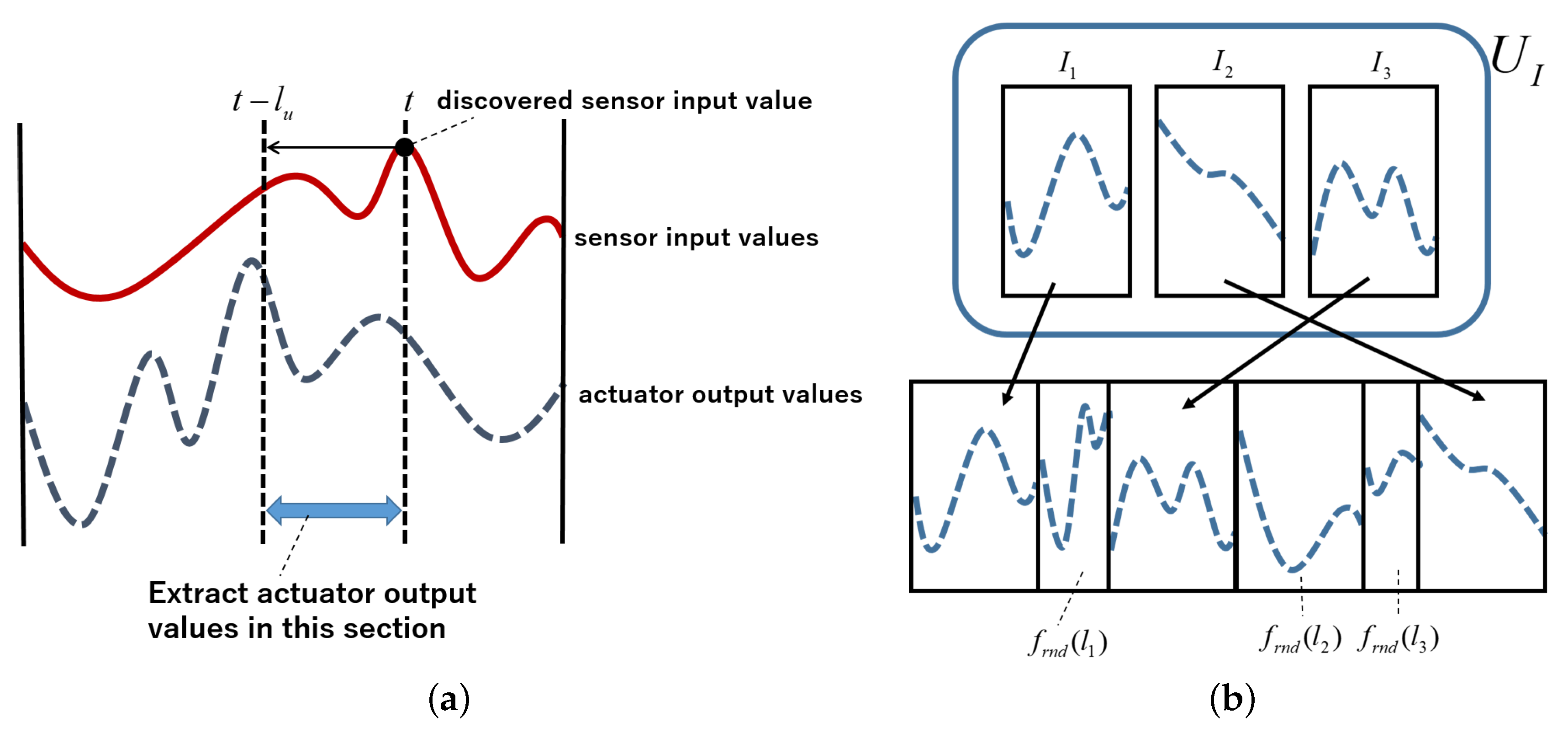
2.1. Definition of an Action Fragment

Our intent was to construct an algorithm to acquire a robot’s base action set that does not depend on a specific task. Also, we wanted to make this base action set usable in many situations (i.e., universal). We chose a base action set that effectively causes changes in the external environment as a candidate. We hypothesized that an action to effectively change the external environment can be observed indirectly through events to find undiscovered sensor values. Discovering sensor values means situations that have never happened before occurred in the external environment. In other words, a robot can be considered to have caused some changes to it.
On the basis of the above, our intent is to generate effective actions that cause changes in the external environment dynamically by generating actuator output signals without using pre-defined actions. Therefore, we define a unit that combines sensor input signals and actuator output signals for analyzing relationships between them. The “action fragment” is defined as a set of sensor input and actuator output signals for a specific period of time.
The number of sensors and actuators are denoted as m and n, respectively. The action fragment of m sensors and n actuators is denoted as F and the data length of the action fragment F is denoted as l. F contains each of the sensor input values and actuator output signals. The ith sensor input signal is denoted as s i , and the jth actuator output signal is denoted as a j . These are expressed as Equations (1)–(3).
F = s 1 , , s m | a 1 , , a n T
s i = s i ( 0 ) , s i ( 1 ) , , s i ( t ) , , s i ( l 1 )
a j = a j ( 0 ) , a j ( 1 ) , , a i ( t ) , , a j ( l 1 )
The action fragment is designed as a part of the robot’s behavior. Thus, the actuator output signals are generated first, and the robot moves according to the signals when we use the action fragment. Then, the robot’s sensor input signals are recorded, and they are combined with the actuator output signals as an action fragment. For example, if we use a differential wheeled robot equipped with two speed-controllable wheels and a forward distance sensor, two actuator output signals are generated and input to the wheels. Then, the sensor input signals are recorded and combined to form the action fragment.

2.2. Action Fragment Operations

Here, we define the union of action fragments. Action fragment F A is defined as Equations (4), (6) and (7) and action fragment F B is defined as Equations (5), (8) and (9). Then, action fragment F C , constructed by combining F A and F B , is defined as Equations (10)–(12), where l A and l B are the data length of F A and F B , respectively. The number of actuators and sensors of F A and F B is the same.
F A = s A 1 , , s A m | a A 1 , , a A n T
F B = s B 1 , , s B m | a B 1 , , a B n T
s A i = s A i ( 0 ) , s A i ( 1 ) , , s A i ( l A 1 )
a A j = a A j ( 0 ) , a A j ( 1 ) , , a A j ( l A 1 )
s B i = s B i ( 0 ) , s B i ( 1 ) , , s B i ( l B 1 )
a B j = a B j ( 0 ) , a B j ( 1 ) , , a B j ( l B 1 )
F C = F A + F B
s C i = [ s A i ( 0 ) , s A i ( 1 ) , , s A i ( l A 1 ) , s B i ( 0 ) , s B i ( 1 ) , , s B i ( l B 1 ) ]
a C j = [ a A j ( 0 ) , a A j ( 1 ) , , a A j ( l A 1 ) , a B j ( 0 ) , a B j ( 1 ) , , a B j ( l B 1 ) ]
Also, the extracted part of action fragment F from t = t s to t = t e is defined as a sub action fragment and denoted as Equation (13).
F t s : t e

2.3. Random Motion Generation Algorithm for Comparison

We define a random motion generation algorithm for comparison before explaining the proposed algorithm. The use of a simple random number as actuator output signals does not work for robot motion in most cases. Therefore, we use a Fourier series to generate random actuator output signals by determining the Fourier coefficients using uniform random numbers. A variety of waves are generated in this way. The jth actuator output signal is determined as Equation (14).
a j ( t ) = b ( j ) + k = 1 n k c k ( j ) c o s ( k t ) + d k ( j ) s i n ( k t )
The operation to generate a random action fragment of length l using this method is denoted as f r n d ( l ) . Coefficients b ( j ) , c k ( j ) , d k ( j ) are reset using uniform random numbers each time f r n d ( l ) is used.
The random motion generation algorithm for comparison is referred to as “Algorithm Random” in this paper, and Algorithm Random uses f r n d ( l ) multiple times to generate actuator output signals of necessary length (Figure 1).

2.4. Base Action Set Generation Algorithm to Extract Actions That Cause Changes Effectively in the External Environment and to Combine Those Actions

We developed a base action set generation algorithm focusing on finding processes of undiscovered sensor values.
First, when a robot finds undiscovered sensor values, we assume that some of the actions that effectively change the external environment are generated around that time. Then, the algorithm extracts a part of the actuator output signals before the undiscovered sensor values are found. These extracted parts are used to generate new actuator output signals by combining them. The newly generated signals should effectively change the external environment and enable finding undiscovered sensor values.
A discovery of new sensor values is defined as follows. First, we divide the m-dimensional sensor space of a robot that has m sensors into several parts and assume each part as a bin of a histogram. This histogram is denoted as D m . Each bin of the m-dimensional histogram D m is denoted as b ( i 1 , i 2 , , i m ) , and the number of data in each bin is denoted as n b ( i 1 , i 2 , , i m ) . The m-dimensional histogram D m at time t is denoted as D m ( t ) . The sensor value at time t s ( t ) is allocated to the corresponding bin. We assume that the corresponding bin of sensor value s ( t ) is b ( i 1 , i 2 , , i m ) . If n b ( i 1 , i 2 , , i m ) = 0 in D m ( t 1 ) , the sensor value s ( t ) is an undiscovered sensor value.
Next, we explain the operations to extract the part of the actuator output signals that have contributed to finding undiscovered sensor values. When a sensor value at time t s ( t ) is an undiscovered sensor value, this operation extracts a part of the actuator output signals from time t l u to time t as a contributed part to find new sensor values. This part is constructed as a sub action fragment of F that records all actuator output signals from time t = 0 . This sub action fragment I i is defined as I i = F [ t l u : t ] (Figure 2a). I i is added to extracted action fragment set U I . The part of the actuator output signals that contributed to finding undiscovered sensor values is extracted and maintained using these operations and used to generate new actuator output signals.
This algorithm uses elements of extracted action fragment set U I when an actuator output signal is newly generated. Now, we describe generating action fragment F p of length l. F p is generated according to Equation (15)–(17), where n ( U I ) is the number of elements of extracted action fragment set U I and l g is a uniform random number in [ l m i n : l m a x ] .
F p = j g ( j )
F p = F p [ 0 : l ]
g ( j ) = I k I k U I , probability ( 1 r r ) n ( U I ) f r n d ( l g ) ( probability r r )
Therefore, this algorithm generates random actuator output signals according to probability r r , chooses an extracted action fragment according to probability 1 r r , and combines these parts to generate new actuator output signals. The details are shown in Figure 2b.

2.5. Discard of Extracted Action Fragments

The length of used I i is denoted as u i and the length of the contributed parts of I i to find the undiscovered sensor values is denoted as v i among all the generated actuator output signals. The parts of I i that contributed to finding the undiscovered sensor values are the parts of I i between time t l u to time t, where the new sensor value is found at time t. Therefore, v i is equal to the summation length of the contained parts of action fragment I i among all the generated action fragments.
Here, we introduce a mechanism that evaluates each action fragment I i to identify and discard any fragment that has not contributed to finding new sensor values. We define discard criterion w i for action fragment I i as
w i = v i u i
Action fragment I i that satisfies w i < w is discarded from extracted action fragment set U I , where constant w is a discard criterion threshold.
The meaning of this operation is explained as follows. Discard criterion w i can be transformed as Equation (19)
w i = v i u i = v i l u i l = P ( I i A ) P ( I i ) = P ( A | I i ) ,
where l is a length of the whole generated actuator output signals. These probabilistic formulations have the following meanings.
  • P ( I i ) : probability to use action fragment I i in a process of actuator output signal generation.
  • P ( I i A ) : probability that a robot both uses I i in a process of actuator output signal generation and finds undiscovered sensor values.
  • P ( A | I i ) : probability that a robot finds undiscovered sensor values when it uses action fragment I i in a process of actuator output signal generation.
Hence, w i expresses the probability that a robot finds undiscovered sensor values when it uses action fragment I i in a process of actuator output signal generation. This operation discards actions fragments when the probability P ( A | I i ) is below the discard criteria threshold w.
A flowchart of the proposed algorithm is shown in Figure 3.

3. Validation of Base Action Set Generation Process Using the Proposed Algorithm through Experiments with a Differential Wheeled Robot

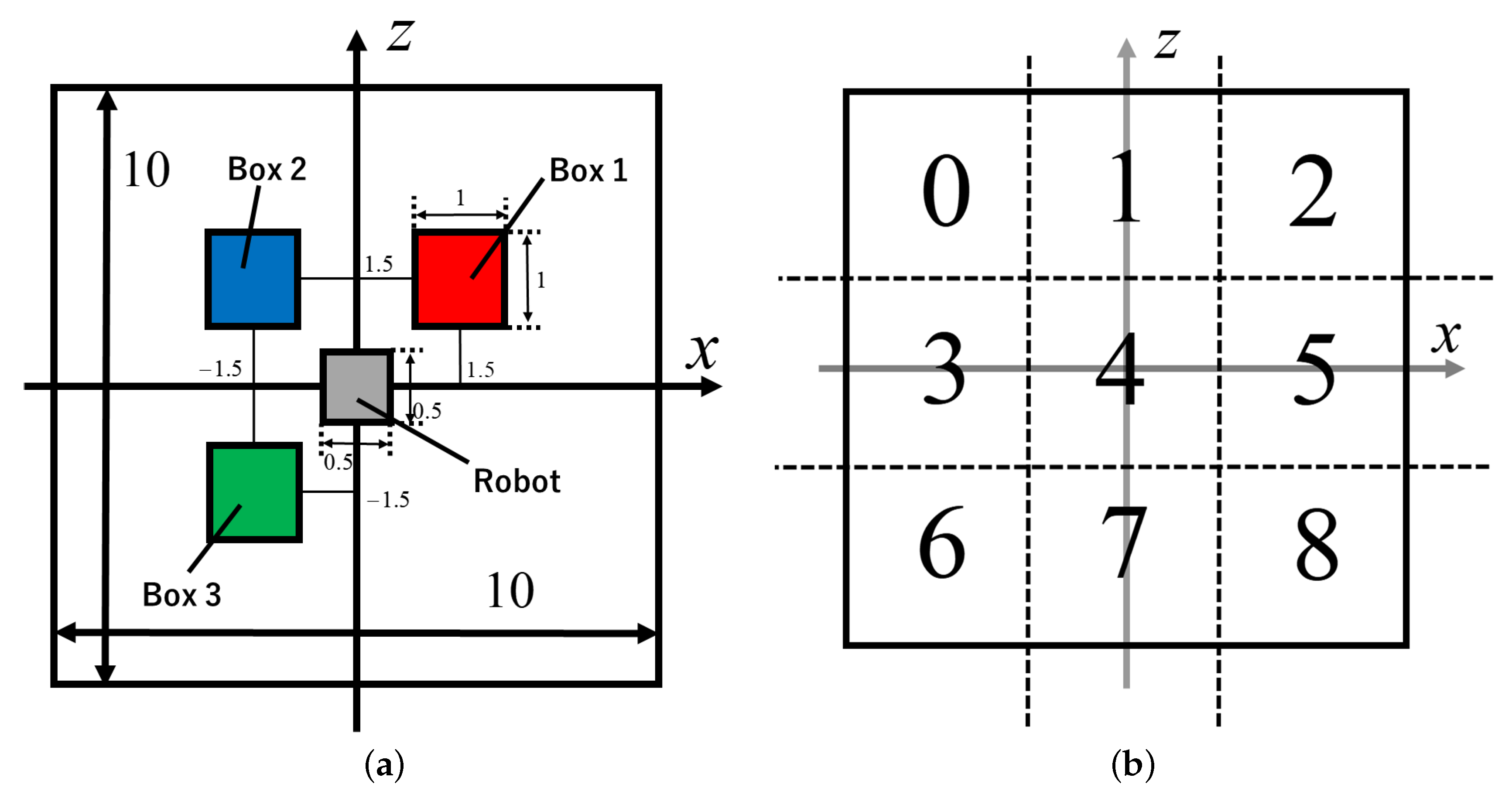
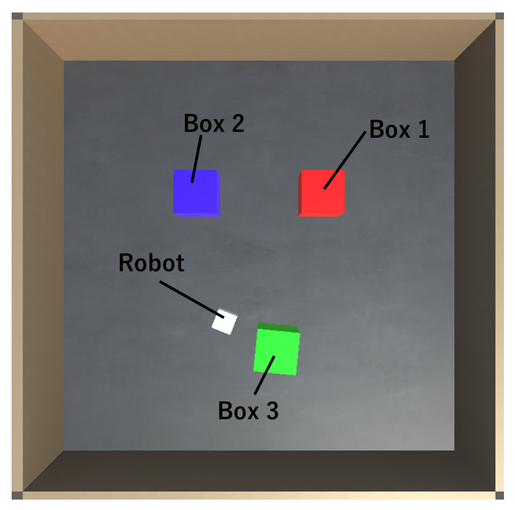
3.1. Experiment Using a Differential Wheeled Robot

We validated the process of base action set generation using the algorithm in a simulation experiment with a differential wheeled robot. The experimental environment is shown in Figure 4a. The experimental field of 10 m × 10 m was surrounded by four walls, and the robot was placed in the center. It had two drive wheels and one caster wheel. The robot weighed 10 kg, and each drive wheel could generate 10 Nm torque at maximum. Boxes of 1 kg were placed around it. The boxes were moved by robot locomotion. The field was divided into the nine spaces shown in Figure 4b, and the regions in which each box was present were calculated. The robot received this information as a sensor input value. For example, it received sensor value s ( t ) = { 4 , 7 , 2 } at time t when Box 1, 2, and 3 were present in regions 4, 7, and 2, respectively. The corresponding bin of s ( t ) was b ( 4 , 7 , 2 ) and s ( t ) was an undiscovered sensor value if n b ( 4 , 7 , 2 ) = 0 at time t 1 . The idea here is to have the algorithm determine which actions will change the external environment and then use them repeatedly to find undiscovered sensor values. A screenshot of the simulation experiment is shown in Figure 5.
1 step of the physics simulation was 0.02 s in this experiment. It is too difficult for the robot to maneuver when boxes are near a wall, so the positions of the boxes and robot were reset to their initial ones every 50,000 step = 50,000 * 0.02 s = 1000 s. Each trial in this experiment was conducted until 200 position resets. We compared three algorithms: A random motion generation algorithm (Algorithm Random), our proposed algorithm(Algorithm A) and Algorithm A without the mechanism for discarding action fragments defined in Section 2.5 (Algorithm A’). Ten trials were executed for each algorithm. In this case, Algorithm Random was the same as Algorithm A without the action fragment extraction and combination mechanism; in other words, Algorithm A maintained its initial state. A three dimensional histogram was prepared for sensor values in Algorithm A and A’. Each dimension of this histogram was divided into nine regions, as shown in Figure 4b, and each sensor value was allocated to a corresponding bin. Thus, this histogram had 9 3 = 729 bins.

3.2. Viewpoints of the Experiment

We focused on the sensor cover rate and distribution of the robot’s motion vectors in this experiment.

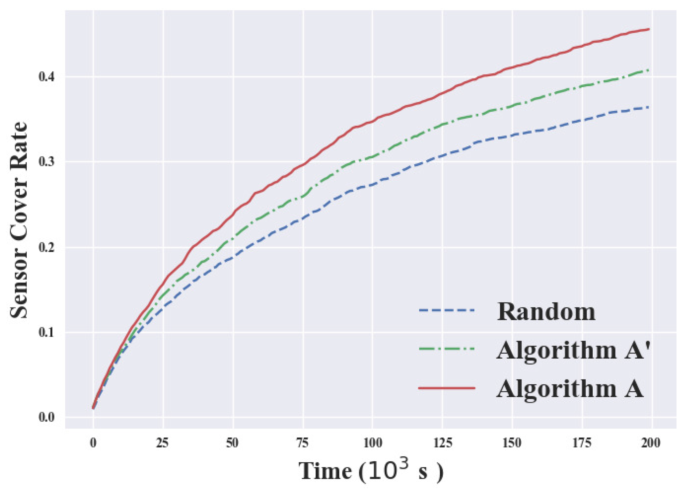
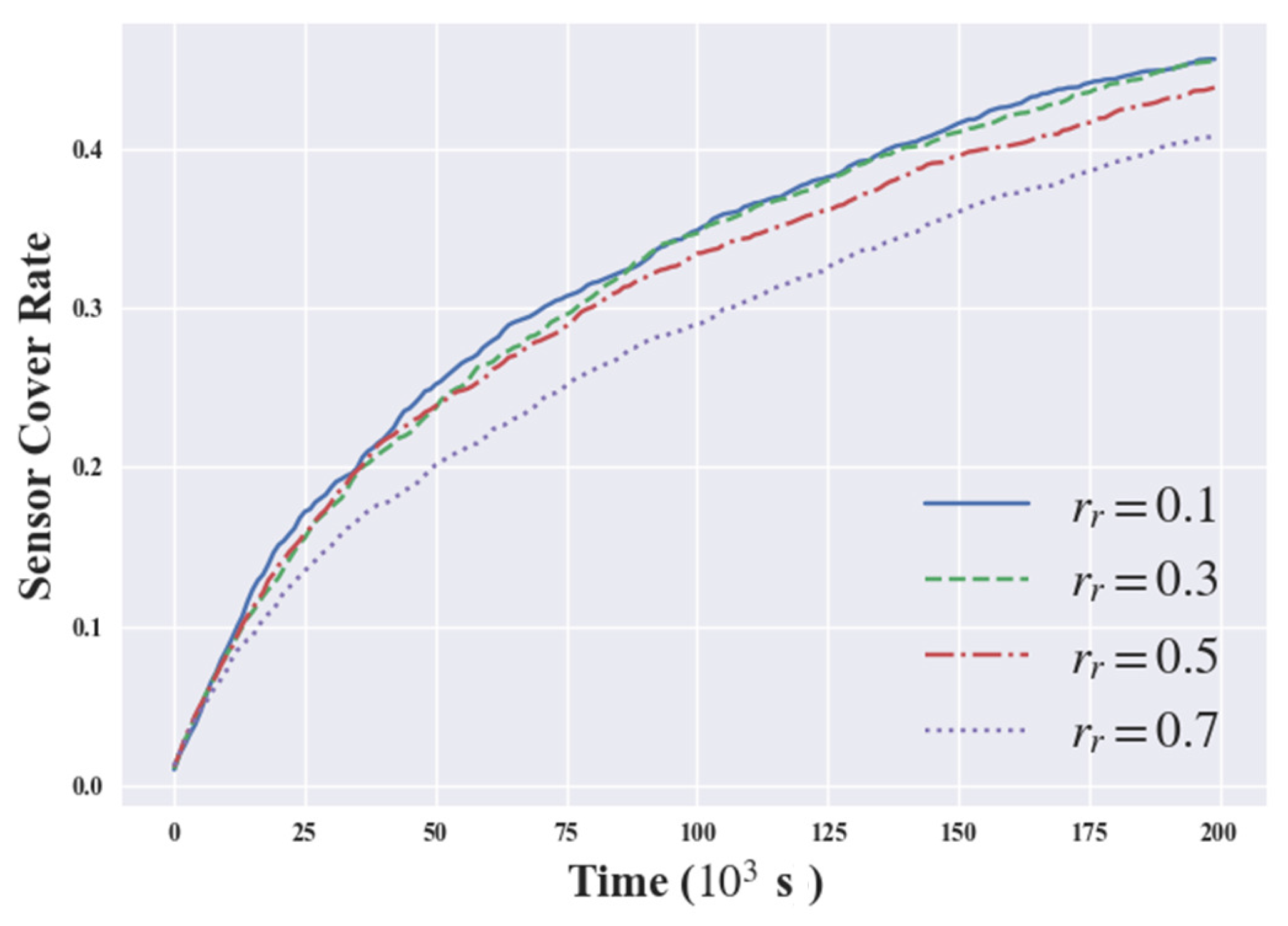
3.2.1. Sensor Cover Rate

The sensor cover rate was defined to observe how many variations in sensor value were discovered. The number of bins satisfying n b ( i 1 , i 2 , , i m ) > 0 in m-dimensional histogram D m of sensor values was denoted as n d , and the number of all bins of D m was denoted as n b i n . Then, sensor cover rate r s was defined as Equation (20).
r s = n d n b i n
The time shift of sensor cover rate r s was observed in this experiment.

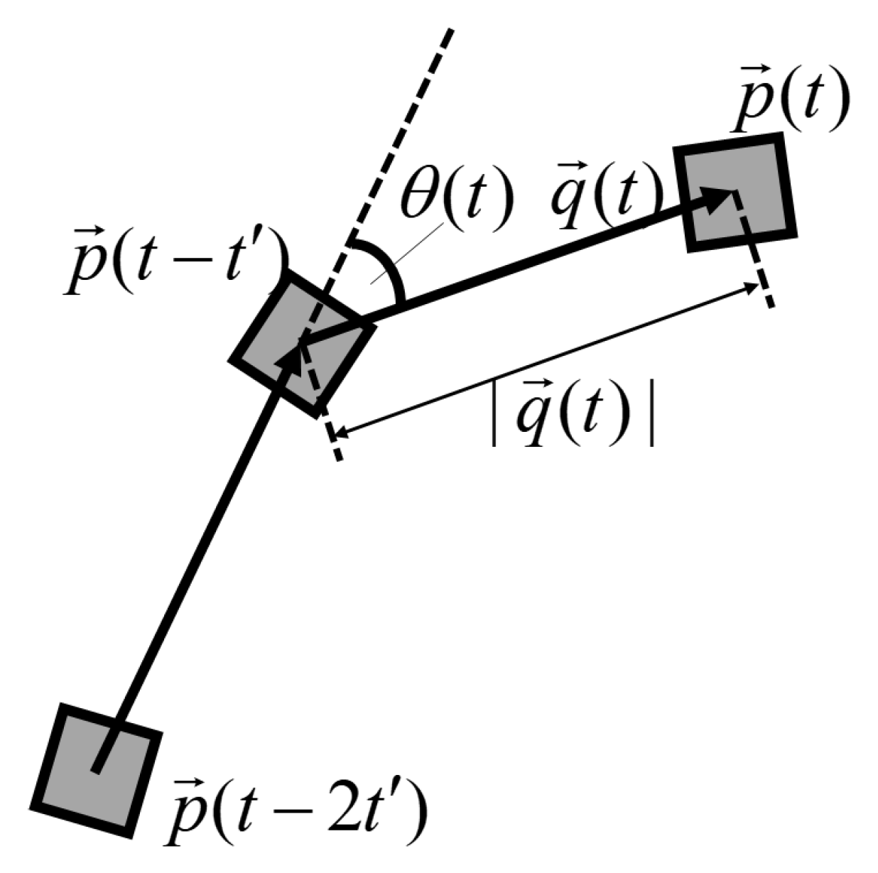
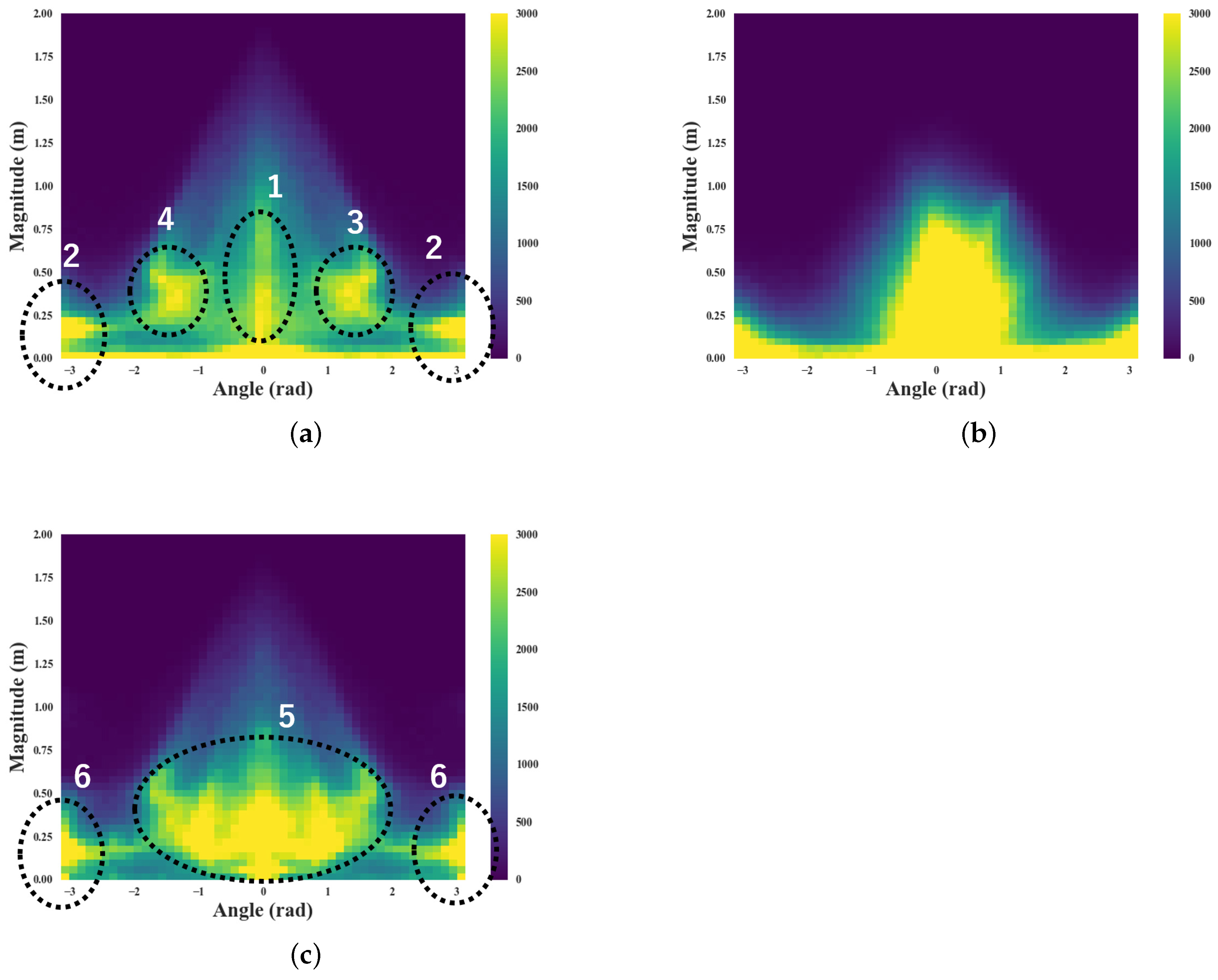
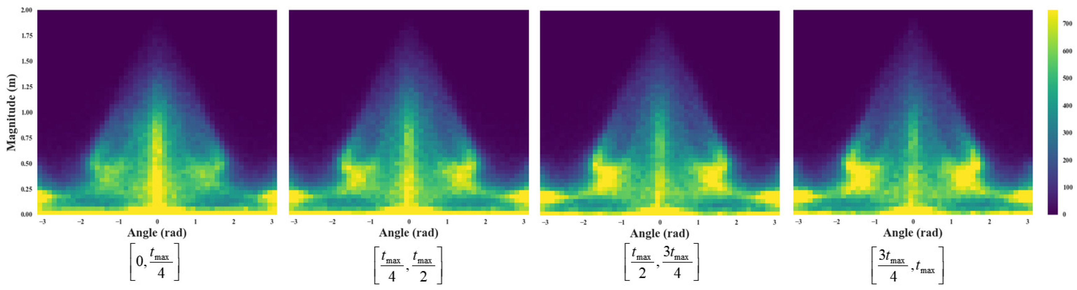
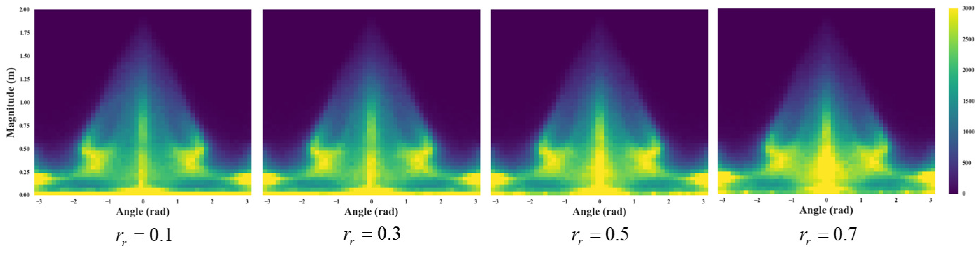
3.2.2. Distribution of the Robot’s Motion Vectors

The motion vectors of the robot at time t q ( t ) were calculated from its position p ( t ) , p ( t t ) , p ( t 2 t ) at regular time interval t as shown in Figure 6.
q ( t ) = p ( t ) p ( t t )
A magnitude of q ( t ) and an angle θ ( t ) between q ( t ) and q ( t t ) were calculated, and the distribution of these values was expressed as a heat map. We determined the actual motion patterns that the robot generated using these results.

3.3. Parameters Settings

The parameter values used in these experiments are enumerated in Table 1.

4. Experimental Results

First, we show our comparison of the time shift of sensor cover rate for each algorithm. The experimental results are shown in Figure 7. Figure 7 shows the average results of ten trials. The sensor cover rate is
A l g o r i t h m A > A > R a n d o m
for the entire time and differences among algorithms increased over time. In particular, the difference between Algorithm A and Algorithm Random at the last time (Time = 200( 10 3 s)) was 0.092 = 9.2 % . The number of all possible sensor value patterns was 9 3 = 729, so Algorithm A found 0.092 729 67 more patterns than Algorithm Random.
The standard deviations of the final sensor cover rate for each algorithm are listed in Table 2. The maximum standard deviation is seen in the results of Algorithm A’, which did not discard the extracted action fragment, and the minimum standard deviation is seen in the results of Algorithm Random.

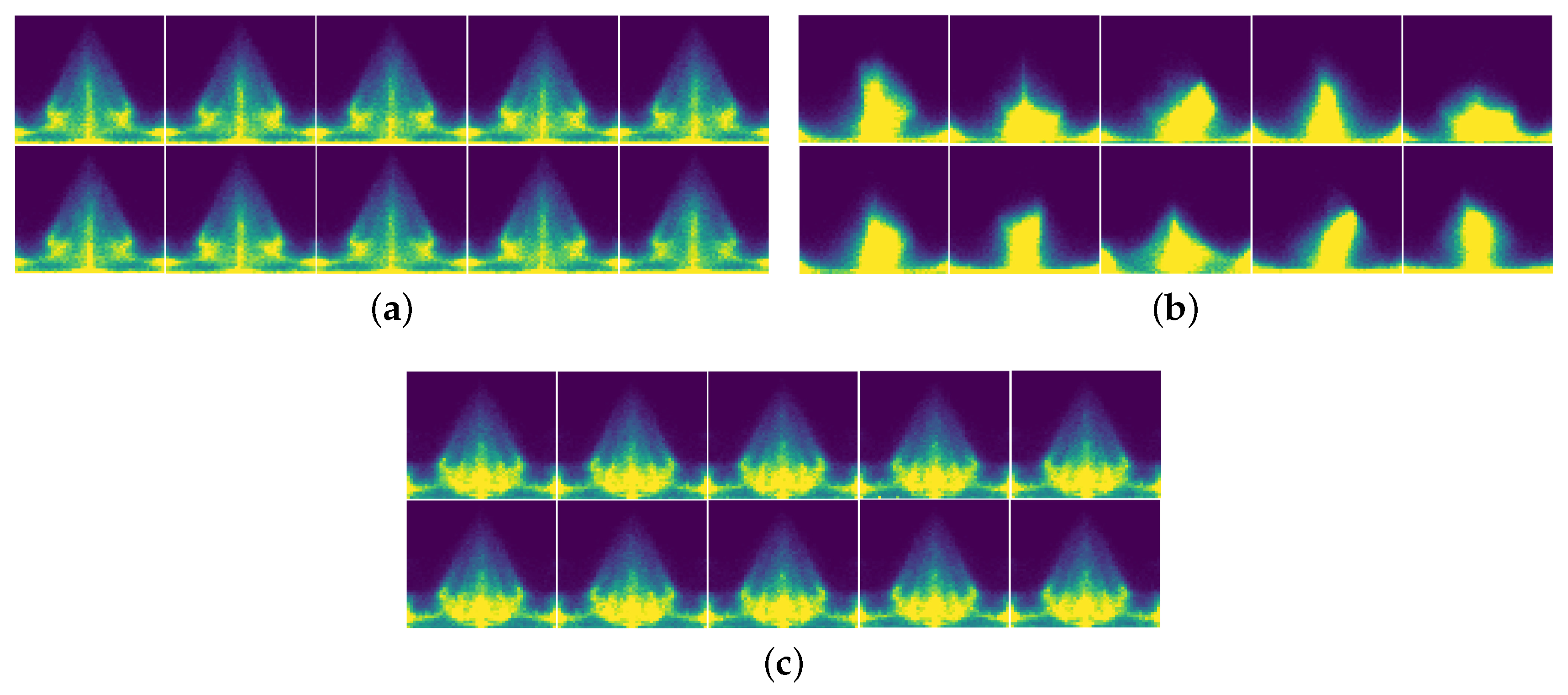
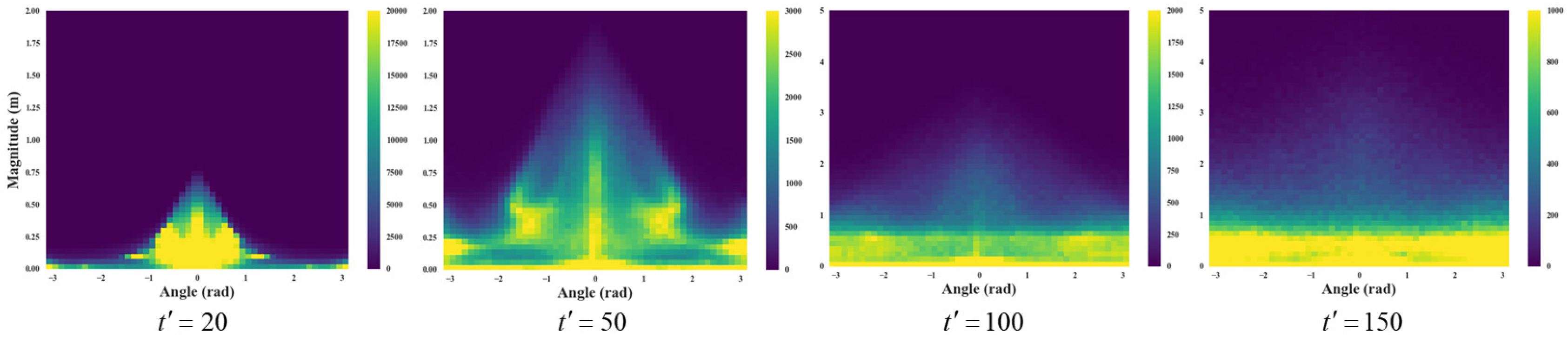
4.1. Visualization of Robot’s Motion Vectors

Next, we enumerated heat maps of the robot’s motion vectors at a regular time interval for each algorithm. The motion vectors were calculated once every 50 steps; in other words, 50 * 0.02 s = 1 s. The horizontal axis in these maps denotes the relative angle θ ( t ) and the vertical axis denotes the magnitude | q ( t ) | . The results of Algorithms A, A’, and Random are shown in Figure 8. These results show all the vectors of ten trials for each algorithm.
In the results for Algorithm A (Figure 8a), strong responses were shown in four sections: “Go forward” (1 in Figure 8a), “Go backward” (2 in Figure 8a), “Turn 90 degrees right” (3 in Figure 8a), and “Turn 90 degrees left” (4 in Figure 8a). This means the robot used these four locomotions frequently. These locomotion selections were comparable to typical wheeled robot locomotions. However, strong responses were observed evenly from turning 90 degrees right to 90 degrees left except for “Go forward” and “Go backward” (6 in Figure 8c) in the results of Algorithm Random (5 in Figure 8c). This means that the robot could only find about 10 % fewer box allocation patterns even though Algorithm Random made more locomotion patterns than Algorithm A. All the heat maps of the ten trials for each algorithm are shown in Figure 9. The distributions of the ten trials were almost the same in Algorithms A and Random. However, the distributions were unstable and variable in Algorithm A’. These results show that discarding action fragments was executed correctly in Algorithm A. Therefore, Algorithm A could determine effective base actions to find undiscovered sensor values. Moreover, Algorithm A discarded actions that did not contribute to finding new sensor values correctly and stabilized its performance.
Next, we divided experiment time t m a x (=200( 10 3 s)) into four parts and enumerated heat maps of the robot’s motion vectors at each part. The four heat maps of Algorithm A with r r = 0.3 , which are the results of ten trials, are shown in Figure 10.
As shown in Figure 10, a heat map in the early phase ( [ 0 , t m a x / 4 ] ) showed strong responses only near the “Go forward” and “Go backward” areas. However, strong responses near “Turn right 90 degrees” and “Turn left 90 degrees” appeared from the second part ( [ t m a x / 4 , t m a x / 2 ] ) and remained almost the same from the third part ( [ t m a x / 2 , 3 t m a x / 4 ] ). These results mean that actions of strong responses in the heat maps were used repeatedly. Therefore, Algorithm A finished extracting the appropriate action fragments until ( [ t m a x / 2 , 3 t m a x / 4 ] ) and then maintained.
Next, we changed the action generation random rate r r and evaluated its effect on acquiring the appropriate action set in Algorithm A. Average sensor cover rates of Algorithm A with various r r are given in Figure 11, which includes the average results of ten trials. Average sensor cover rate increased for the entire time in accordance with the decrease of r r from 0.7 to 0.3. In contrast, they remained almost the same when r r decreased from 0.3 to 0.1. Heat maps of the robot’s motion vectors for each r r value are shown in Figure 12. Here, as the action generation random rate increases, the results show distributions similar to the result of Algorithm Random ( r r = 1.0 ) that distributed between angle θ = π / 2 to θ = π / 2 uniformly. However, the heat maps of r r = 0.1 and 0.3 are almost the same and showed strong responses in all four areas, as in Figure 8a.
Finally, we changed the interval time t of the robot’s motion vectors and show the heat maps of each case in Figure 13. All motion vectors of ten trials by Algorithm A with r r = 0.3 are shown in Figure 13. The result of t = 50 was the same as the result in Figure 8a and all four areas showed strong responses. However, distributions were located on the specific area and distributed uniformly inside the area when t = 20 , 100 , and 150. Thus, no specific strong response was observed in those cases. This is because the action fragment extraction length was l u = 50 , and generated action sequences have meaning only when l u = t .

4.2. Discussion

We found that our proposed algorithm, which features action extraction and combination mechanisms of contributed action fragments, can find more undiscovered sensor values than a random action generation algorithm that is equal to the initial state of the proposed algorithm. Also, appropriate extraction of action fragments in Algorithm A was observed from the results of Figure 10. Four actions showing strong responses were repeatedly used and maintained in Figure 10, and the sensor cover rate of Algorithm A was the highest in Figure 7. Therefore, undiscovered sensor values were found by using those four extracted actions repeatedly, i.e., they were not discarded.
Thus, the action discarding mechanism is effective for removing action fragments that do not contribute to finding undiscovered sensor values and helps stabilize the performance. Algorithm A with the smaller action generation random rate r r had a better sensor cover rate in Figure 11. This result demonstrates that undiscovered sensor values could be found effectively by using the action generation method that combines extracted action fragments in Algorithm A. However, sensor cover rates were almost the same when r r 0.3 and its effectiveness in finding undiscovered sensor values peaked around r r = 0.3 . Thus, r r should be around 0.3 when we use this algorithm. The robot found undiscovered sensor values effectively, meaning the extracted actions the robot used repeatedly changed the external environment capably and generated new situations. Four types of actions—“Go forward”, “Go backward”, “Turn right 90 degrees”, and “Turn left 90 degrees”—were extracted and used frequently as the base actions of a differential wheeled robot in this experiment. These base actions differ depending on changes in the environment and the robot body. Base actions can easily be set by hand if both the environment and robot body are simple—like they were in this experiment. However, this would not be possible for a complicated robot body and/or a constantly changing environment. In such cases, the algorithm can obtain a base action set to change the external environment capably.
Finally, from the results of Figure 13, generated actions depending on action fragment extraction length l u and biased distribution of robot action could be observed when t = l u . This means that l u should be larger if longer action is needed. Thus, if the robot needs actions of various time scales, l u should be changed in accordance with the situation. This issue will be addressed in future work.

5. Conclusions

We demonstrated that the proposed algorithm is capable of effectively obtaining a base action set to change the external environment, and that the actions in the base action set contribute to finding undiscovered sensor values. Also, we showed that the algorithm stabilizes its performance by discarding actions that do not contribute to finding undiscovered sensor values. We examined the effects and characteristics of the parameters in the proposed algorithm and clarified the suitable value range of parameters for robot applications. Applying a flexible time scale for extracting action fragments is left for future work. We also intend to investigate the effect of using the action set acquired by the proposed algorithm in conventional learning methods as a base action set. We assume that an action set acquired by the proposed algorithm is both universal and effective. Thus, we will investigate whether the action set acquired by the proposed algorithm can improve the performance of conventional machine learning methods such as reinforcement learning. Also, we will construct a method to share learning data among different tasks by using the universal action set acquired by the proposed algorithm in such cases.

Author Contributions

Investigation, S.Y.; Project administration, K.S.; Writing—original draft, S.Y.; Writing—review and editing, K.S.

Funding

This research received no external funding.

Conflicts of Interest

The authors declare no conflict of interest.

References

  1. Lungarella, M.; Metta, G.; Pfeifer, R.; Sandini, G. Developmental robotics: A survey. Connect. Sci. 2003, 15, 151–190. [Google Scholar] [CrossRef]
  2. Kaelbling, L.P.; Littman, M.L.; Moore, A.W. Reinforcement learning: A survey. J. Artif. Intell. Res. 1996, 4, 237–285. [Google Scholar] [CrossRef]
  3. Scheier, C.; Pfeifer, R. Classification as sensory-motor coordination. In Proceedings of the Third European Conference on Artificial Life, Granada, Spain, 4–6 June 1995; Springer: Berlin, Germany, 1995; pp. 657–667. [Google Scholar]
  4. Zhu, Y.; Mottaghi, R.; Kolve, E.; Lim, J.J.; Gupta, A.; Li, F.F.; Farhadi, A. Target-driven visual navigation in indoor scenes using deep reinforcement learning. In Proceedings of the 2017 IEEE International Conference on Robotics and Automation (ICRA), Singapore, 29 May–3 June 2017; pp. 3357–3364. [Google Scholar]
  5. Qureshi, A.H.; Nakamura, Y.; Yoshikawa, Y.; Ishiguro, H. Robot gains social intelligence through multimodal deep reinforcement learning. In Proceedings of the 2016 IEEE-RAS 16th International Conference on Humanoid Robots (Humanoids), Cancun, Mexico, 15–17 November 2016; pp. 745–751. [Google Scholar]
  6. Lei, T.; Ming, L. A robot exploration strategy based on q-learning network. In Proceedings of the IEEE International Conference on Real-time Computing and Robotics (RCAR), Angkor Wat, Cambodia, 6–10 June 2016; pp. 57–62. [Google Scholar]
  7. Riedmiller, M.; Gabel, T.; Hafner, R.; Lange, S. Reinforcement learning for robot soccer. Auton. Robot. 2009, 27, 55–73. [Google Scholar] [CrossRef] [Green Version]
  8. Matarić, M.J. Reinforcement Learning in the Multi-robot Domain. Auton. Robot. 1997, 4, 73–83. [Google Scholar] [CrossRef]
  9. Sutton, R.S.; Barto, A.G.; Barto, A.G.; Bach, F. Reinforcement Learning: An Introduction; MIT Press: Cambridge, MA, USA, 1998. [Google Scholar]
  10. Mitchell, T.M.; Thrun, S.B. Explanation-based neural network learning for robot control. In Proceedings of the 5th International Conference on Neural Information Processing Systems, Denver, CO, USA, 30 November–3 December 1992; pp. 287–294. [Google Scholar]
  11. Pfeiffer, M.; Nessler, B.; Douglas, R.J.; Maass, W. Reward-modulated hebbian learning of decision making. Neural Comput. 2010, 22, 1399–1444. [Google Scholar] [CrossRef] [PubMed]
  12. Hafner, R.; Riedmiller, M. Neural reinforcement learning controllers for a real robot application. In Proceedings of the 2007 IEEE International Conference on Robotics and Automation, Roma, Italy, 10–14 April 2007; pp. 2098–2103. [Google Scholar]
  13. Kormushev, P.; Calinon, S.; Caldwell, D.G. Reinforcement learning in robotics: Applications and real-world challenges. Robotics 2013, 2, 122–148. [Google Scholar] [CrossRef]
  14. Kober, J.; Peters, J.R. Policy search for motor primitives in robotics. In Advances in Neural Information Processing Systems; Curran Associates: Vancouver, BC, Canada, 2009; pp. 849–856. [Google Scholar]
  15. Shen, H.; Yosinski, J.; Kormushev, P.; Caldwell, D.G.; Lipson, H. Learning fast quadruped robot gaits with the RL power spline parameterization. Cybern. Inf. Technol. 2012, 12, 66–75. [Google Scholar] [CrossRef]
  16. Ijspeert, A.J.; Nakanishi, J.; Schaal, S. Learning attractor landscapes for learning motor primitives. In Advances in Neural Information Processing Systems; Curran Associates: Vancouver, BC, Canada, 2003; pp. 1547–1554. [Google Scholar]
  17. Kimura, H.; Yamashita, T.; Kobayashi, S. Reinforcement learning of walking behavior for a four-legged robot. IEEJ Trans. Electron. Inf. Syst. 2002, 122, 330–337. [Google Scholar] [Green Version]
  18. Shibata, K.; Okabe, Y.; Ito, K. Direct-Vision-Based Reinforcement Learning Using a Layered Neural Network. Trans. Soc. Instrum. Control Eng. 2001, 37, 168–177. [Google Scholar] [CrossRef] [Green Version]
  19. Goto, Y.; Shibata, K. Emergence of higher exploration in reinforcement learning using a chaotic neural network. In Proceedings of the International Conference on Neural Information Processing, Siem Reap, Cambodia, 13–16 December 2018; Springer: Berlin, Germany, 2016; pp. 40–48. [Google Scholar]
  20. Dutta, A.; Dasgupta, P.; Nelson, C. Adaptive locomotion learning in modular self-reconfigurable robots: A game theoretic approach. In Proceedings of the 2017 IEEE/RSJ International Conference on Intelligent Robots and Systems (IROS), Vancouver, BC, Canada, 24–28 September 2017; pp. 3556–3561. [Google Scholar] [CrossRef]
  21. Lample, G.; Chaplot, D.S. Playing FPS Games with Deep Reinforcement Learning. In Proceedings of the Conference on Artificial Intelligence AAAI, San Francisco, CA, USA, 4–9 February 2017; pp. 2140–2146. [Google Scholar]
  22. Sallab, A.E.; Abdou, M.; Perot, E.; Yogamani, S. Deep reinforcement learning framework for autonomous driving. Electron. Imaging 2017, 2017, 70–76. [Google Scholar] [CrossRef]
  23. Ran, L.; Zhang, Y.; Zhang, Q.; Yang, T. Convolutional neural network-based robot navigation using uncalibrated spherical images. Sensors 2017, 17, 1341. [Google Scholar] [CrossRef] [PubMed]
  24. Taki, R.; Maeda, Y.; Takahashi, Y. Generation Method of Mixed Emotional Behavior by Self-Organizing Maps in Interactive Emotion Communication. J. Jpn. Soc. Fuzzy Theory Intell. Inform. 2012, 24, 933–943. [Google Scholar] [CrossRef] [Green Version]
  25. Gotoh, M.; Kanoh, M.; Kato, S.; Kunitachi, T.; Itoh, H. Face Generation Using Emotional Regions for Sensibility Robot. Trans. Jpn. Soc. Artif. Intell. 2006, 21, 55–62. [Google Scholar] [CrossRef]
  26. Matsui, Y.; Kanoh, M.; Kato, S.; Nakamura, T.; Itoh, H. A Model for Generating Facial Expressions Using Virtual Emotion Based on Simple Recurrent Network. JACIII 2010, 14, 453–463. [Google Scholar] [CrossRef]
  27. Yano, Y.; Yamaguchi, A.; Doki, S.; Okuma, S. Emotional Motion Generation Using Emotion Representation Rules Modeled for Human Affection. J. Jpn. Soc. Fuzzy Theory Intell. Inform. 2010, 22, 39–51. [Google Scholar] [CrossRef]
Figure 1. Overview of random motion generation.
Applsci 09 00161 g001
Figure 2. Motion extraction and motion generation. (a) Method to extract effective motion for finding undiscovered sensor values; (b) Motion generation using extracted effective motion.
Applsci 09 00161 g002
Figure 3. Flowchart of proposed algorithm.
Applsci 09 00161 g003
Figure 4. Experiment settings. (a) Experimental environment (Unit: meters); (b) Sensor division area of boxes.
Applsci 09 00161 g004
Figure 5. Screenshot of experiment.
Applsci 09 00161 g005
Figure 6. Motion vectors of a robot.
Applsci 09 00161 g006
Figure 7. Sensor cover rate of each algorithm
Applsci 09 00161 g007
Figure 8. Motion vector heat map of each algorithm. (a) Algorithm A; (b) Algorithm A’; (c) Algorithm Random.
Applsci 09 00161 g008
Figure 9. Motion Vector heat map of each trial. (a) Algorithm A; (b) Algorithm A’; (c) Algorithm Random.
Applsci 09 00161 g009
Figure 10. Motion vector heat map of each time section of Algorithm A with r r = 0.3 .
Applsci 09 00161 g010
Figure 11. Sensor cover rate of various r r values.
Applsci 09 00161 g011
Figure 12. Motion vector heat map of various r r values.
Applsci 09 00161 g012
Figure 13. Motion vector heat map of various time intervals.
Applsci 09 00161 g013
Table 1. Experiment parameters.
Action fragment extraction length l u = 50
Action generation random rate r r = 0.3
Discard criterion threshold w = 0
Time interval of motion vectors t = 50
Minimum length of random motion generation l m i n = 10
Maximum length of random motion generation l m a x = 50
Table 2. Final standard deviation of each algorithm.
AlgorithmStandard Deviation
Algorithm A0.0261
Algorithm A’0.1443
Algorithm Random0.0102

