Article

Analysis of the Deviation in a Low-Cost System for Stepless Digital Control of Conventional Lathe Spindle Speeds

by
Tadeusz Mikolajczyk
1,
Tomasz Paczkowski
1,
Danil Yurievich Pimenov
2,*,
Mozammel Mia
3,
Karali Patra
4,
Grzegorz Krolczyk
5,
Munish Kumar Gupta
6 and
Jaroslaw Zdrojewski
7
1
Department of Production Engineering, UTP University of Science and Technology, Al. prof. S. Kaliskiego 7, Bydgoszcz 85-796, Poland
2
Department of Automated Mechanical Engineering, South Ural State University, Lenin Prosp. 76, Chelyabinsk 454080, Russia
3
Mechanical and Production Engineering, Ahsanullah University of Science and Technology, Dhaka 1208, Bangladesh
4
Department of Mechanical Engineering, Indian Institute of Technology Patna, Bihta Patna 801103, India
5
Faculty of Mechanical Engineering, Opole University of Technology, 76 Proszkowska St., Opole 45-758, Poland
6
Department of Mechanical Engineering, Chandigarh University, Gharuan, Punjab 140413, India
7
Department of Digital Technology, UTP University of Science and Technology, Al. prof. S. Kaliskiego 7, Bydgoszcz 85-796, Poland
*
Author to whom correspondence should be addressed.
Appl. Sci. 2019, 9(1), 12; https://doi.org/10.3390/app9010012
Submission received: 3 December 2018 / Revised: 17 December 2018 / Accepted: 18 December 2018 / Published: 20 December 2018

Abstract

:
A conventional manual lathe electric motor drives the multi-stage gearbox transmitting torque to the spindle so that the workpiece makes contact with the machine tool at a given speed. The cutting speed is proportional to both the diameter of the workpiece and the spindle speed, however, the increments in spindle speed are limited. Manual lathe machines cannot be regulated at the optimum cutting speeds for all diameters. An innovative modernization of the main driveline of a TSB16 manual lathe is proposed in this paper, allowing for a cost-effective system for digital control of spindle speeds using an inverter. The inverter is controlled using an 8-bit AO (analog output) converter with special software developed with Visual Basic. The results of the analysis and various test runs with this new system for automated control of spindle rotation, showed that the required cutting speed can be achieved for any workpiece diameter. The deviation of cutting-speed of the upgraded system for any turning diameter is greatly reduced in comparison with the deviation of cutting-speed of a manual lathe. Finally, tests on this versatile system demonstrated a cost-effective method for modernizing the drive system of conventional lathe machines.

1. Introduction

Technological advances have led to the modernization of both the control and the power train systems installed in a range of machinery. In many cases, the drive speeds may be regulated by the system, significantly increasing the machining capacity and workable tool life.
The market share for numerically controlled machine tools continues to expand. Computer numerical control (CNC) machine tools are demonstrably of higher accuracy and efficiency than manual machines. Progress in the field of electronics, information technology, and control algorithms now mean that this type of machine incorporates advanced supervision and control systems. The ultimate goal here, is to increase both the productivity and the accuracy of machine tools and to improve their programming. One example of the measures used to achieve this goal is the use of speed control.
Many studies have been devoted to studying the effect of cutting speed on turning parameters. Raja and Baskar [1] attempted to determine optimum cutting speeds, feed rates, and cutting depths to minimize machining times and to achieve the required surface roughness in CNC turning of brass, aluminum, copper, and mild-steel workpieces. The results demonstrated stepless changes in cutting speeds. However, some machine tools will not permit certain cutting speeds to be set. Fernández-Abia et al. [2] studied the influence of cutting speed on tool wear, cutting power, surface roughness, and chip geometry in the turning of AISI 303 austenitic stainless steel. Having investigated both a wide range of cutting speeds and the possibility of setting a fixed cutting speed, the results showed maximum levels of efficiency in the management of the aforementioned parameters. Dimla [3] demonstrated the role of cutting depth, speed, and feed rate on time domain and frequency domain signals at different stages of tool wear. Brožek [4] presented the optimized results of a technical study conducted on overlay type machining. The input parameters such as tool life, T-cutting speed and vc ratios were successfully considered to determine the optimal cutting conditions for minimum production costs. In another study, the effect of fluid pressure along with different cutting speeds on mechanisms of tool wear during turning of AISI 1045 steel with coated carbide inserts were investigated by Diniz et al. [5]. Urbikain et al. [6] proposed a model for chatter that was applicable for interrupted turning. The main condition was that the direction of dominant vibration was perpendicular to the chip section plane. Moreover, the controlling factors were machining speed, feed of tool, and the thickness of machining.
Artamonov and Vasil’ev [7] presented a method for determining the optimal cutting speed based on the chipping mechanism and type of chip. Their approach minimized the effort needed for determining the optimal cutting speed and the amount of chip. Nikolaenko [8] proposed mathematical models for the components that comprise cutting force, the power consumed in cutting, and workpiece temperature in high-speed turning, demonstrating the advantages of high-speeds over conventional turning speeds. Anukhin et al. [9] developed a thermal imaging method to select the optimal cutting conditions for high-temperature intermetallic alloys used in the aviation industry. Garg et al. [10] presented a detailed review focusing on the power issue and tool life expectancy with the help of statistical approaches in manufacturing specified products. These studies have clearly demonstrated that the influence of cutting speed is more dominant on selected responses. McParland et al. [11] presented a novel means of estimating the effect of feed rate and cutting speed on the rate of tool wear, as related to changes in the three force components in the turning of a difficult-to-cut medical grade Co–Cr–Mo (ASTM F75) alloy. Johansson et al. [12] evaluated the performance of different work-tool combinations. Variations in the materials and tool grades were common. The turning tests were performed to evaluate the tool performance criteria, and eventually the found results were satisfactory.
Arruda and Brandão [13] used seamless tubular workpieces to define surface roughness and tool wear while turning using a cold/dry air system. The results demonstrated significant reductions in tool life at high cutting speeds. Increased cutting speeds also reduced the cutting effort, both in dry and cold air cutting conditions. Prasad et al. [14] used infrared thermographic monitoring to determine the impact of feed, cutting speed, and depth on machine tool vibrations, tool tip/chip temperatures and surface roughness. With active control of the speed of the main drive, the dynamic state often associated with machine-tool vibrations can be avoided.
Many researchers have also studied the impact of cutting speed on surface roughness, cutting forces, and tool life in turning operations using experimental and artificial intelligence methods. Mia and Dhar [15] predicted the surface quality parameter by the adoption of different neural network algorithms. The surface roughness (Ra) was modeled in terms of cutting speed, feed rate and cooling conditions. Tanikić and Marinković [16] used regression analysis for modeling surface roughness in dry single-point turning and for its optimization. They demonstrated the decreasing tendency of surface roughness at increasing cutting speeds and decreasing feed rate and cutting depth. Using an artificial intelligence approach and statistical method, Mia and Dhar [17] developed prediction and optimization models for the average surface roughness parameter. The behavior of the surface roughness parameter was justified by analytical relationships. Rao et al. [18] estimated the effects of cutting parameters (speed, feed, nose radius) on workpiece vibration, machined surface roughness, and the volume of metal removed in steel boring operations (AISI1040). Günay and Yücel [19] optimized the cutting speeds, feed rates and depth of cut values for minimizing the surface roughness during the turning of Ni-hard materials with ceramic and cubic boron nitride (CBN) tools. Mia [20] employed a machine learning approach to solve the optimization problem for surface roughness in turning hardened steel under sustainable cooling condition.
In a study by Khan et al. [21], tool wear was monitored when employing various insert shapes and geometries, using low policrystaline cubic boron nitride (PCBN) inserts and tool-edge preparation, tool coatings, fluid pressure, cutting speeds, and feed rates in the finish turning of Inconel 718. Özbek et al. [22] studied the impact of the tool-nose radius on residual stress and flank wear over time at various cutting speeds and feed rates in the face turning of Inconel 718. Zou et al. [23] studied the impact of cutting speed, feed rates, and depth of cut on tool life and surface quality in the turning of Ti(C7N3)/WC/TaC cement cutting tools. Jurkovic et al. [24] also made the comparison of three machine learning techniques for prediction of Ra, cutting force (formula presented), and tool lifetime (T) during high speed turning. Orra and Choudhury [25] built an adaptive feedback linear control system to check the variation in cutting force signals to improve tool life. They discussed the use of the transfer function approach for improving mathematical modelling and adaptive control of the process dynamics of turning operations. Mia et al. [26] performed turning experiments on Ti-6Al-4V alloy under dry and high-pressure cooling conditions. The cutting inserts used were coated carbides and the surface quality (in terms of speed and feed) as well as tool wear (in terms of machining time) was discussed. Abbas et al. [27] calculated the Pareto frontier for surface roughness, Ra, and the minimal machining time of a unit volume, Tm, of a finished high-strength steel workpiece using an artificial neural network model that was subsequently used for determining the optimal cutting speed vc, feed rate, f, and depth of cut, ap. Rogante [28] presented a tool condition monitoring study on the dry cutting process using observations of the tool life supported by the Taylor tool life model.
Babouri et al. [29] investigated the condition of tools in terms of wear phenomenon and tool-life transition. The experiments consisted of turning operations on AISI D3 steel using a tool coated with a ceramic intermediate layer (TiCN/Al2O3/TiN). Mikołajczyk et al. [30] presented a study on the automatic prediction of tool life in turning operations. Aramesh et al. [31] investigated the remaining useful tool life under different values of cutting parameters in the turning of Ti-MMC using the actual tool wear value of the worn tool as the input data. Maximum flank wear length at the transition point between the second and third state of tool wear was chosen as the failure criteria.
All of the above studies have demonstrated that cutting speed has the highest influence on tool life. Most of these works applied CNC machines to select different spindle speeds that would achieve the required cutting speed for tools/workpieces of different diameters. However, commercial CNC machines are generally very costly and sometimes machine stability is compromised in an effort to reduce costs. It is worth recalling that many micro- and small-scale machining industries in various countries still utilize conventional machine tools with limited options for controlling spindle speed to produce machined components of different shapes and sizes. The massive size of conventional machines ensures the stability of the machining process. However, limited regulation of spindle speeds can only be obtained in conventional machines with belt drives and gear trains. Under such conditions, it is as difficult to achieve optimum cutting speeds for different diameters of workpiece/tool as it is to achieve the desired productivity. The upgrading of conventional machine tools that are still in good condition is a convenient way of improving productivity. The modernization of such machines can be done through improvements in the drive system and the use of a numerically controlled feed rate. Of course, the economic and technical feasibility of such a process should be carefully considered in each case. The use of an inverter to upgrade the drive is a particularly easy and cost-effective means of modernization [32].
In view of the above facts, the purpose of this paper is to present a versatile system for controlling the spindle speed of a conventional lathe and to demonstrate its benefits by establishing the optimal cutting-speed settings for different workpiece diameters.
This article is presented in three sections:
  • First, the materials and methods (Analysis of analog output (AO) influence on deviation, conventional and proposed drive system of lathe) are presented,
  • Second, the results of analysis speed errors using conventional and new systems of drive are presented and the results are discussed,
  • Third, the conclusions of the study are made.
The study was performed by using an inverter controlled by a computer system to achieve a continuously variable speed control. Furthermore, the analysis of error using digital control system of inverter is presented.

2. Materials and Methods

In this section we present:
  • The analysis of the effect of AO converter resolution on the deviation of output voltage,
  • The conventional drive system of a lathe,
  • Lathe-drive regulation with an inverter.

2.1. Analysis of the Effect of Analog Output Converter Resolution on Deviation of Output Voltage

The conceptual basis of stepless control through the use of an inverter can be outlined as follows. A standard inverter was equipped with a manual control to adjust frequency with an analog potentiometer. Each inverter may be adjusted using an external signal. Both voltage (mV) and current (mA) signals may be used and the signals can be received using an AO (analog output) converter connected to a microcomputer. This interface may be used at various resolutions, as both 8-bit and higher resolutions are possible (Table 1). The typical AO output is 5000 mV. A minimal step in the voltage was calculated at this stage for other resolutions of the AO interfaces. For example, minimal steps of 19.608 mV and 4.888 mV were achieved at resolutions of 8 and 10-bits, respectively. This is an absolute error of output voltage.
On the basis of Table 1, the deviation re of the voltage signal generated by the AO converter for the 8, 10, and 12-bit transmission rates were estimated using the following equation:
reAO = aeAO/U × 100%
The values of reAO decrease significantly with the voltage growth (Figure 1). The graph (Figure 1) displays a range of up to 1000 mV or 20% of the maximum value of a voltage of 5000 mV.
Figure 1 shows the low deviation at higher voltages and particularly high deviation values within the low voltage range, especially for the 8-bit resolution of AO. This error is much lower at higher resolutions of AO, due to the step changes in the voltage of the AO converter, especially at low voltage output.

2.2. The Conventional Drive System of a Lathe

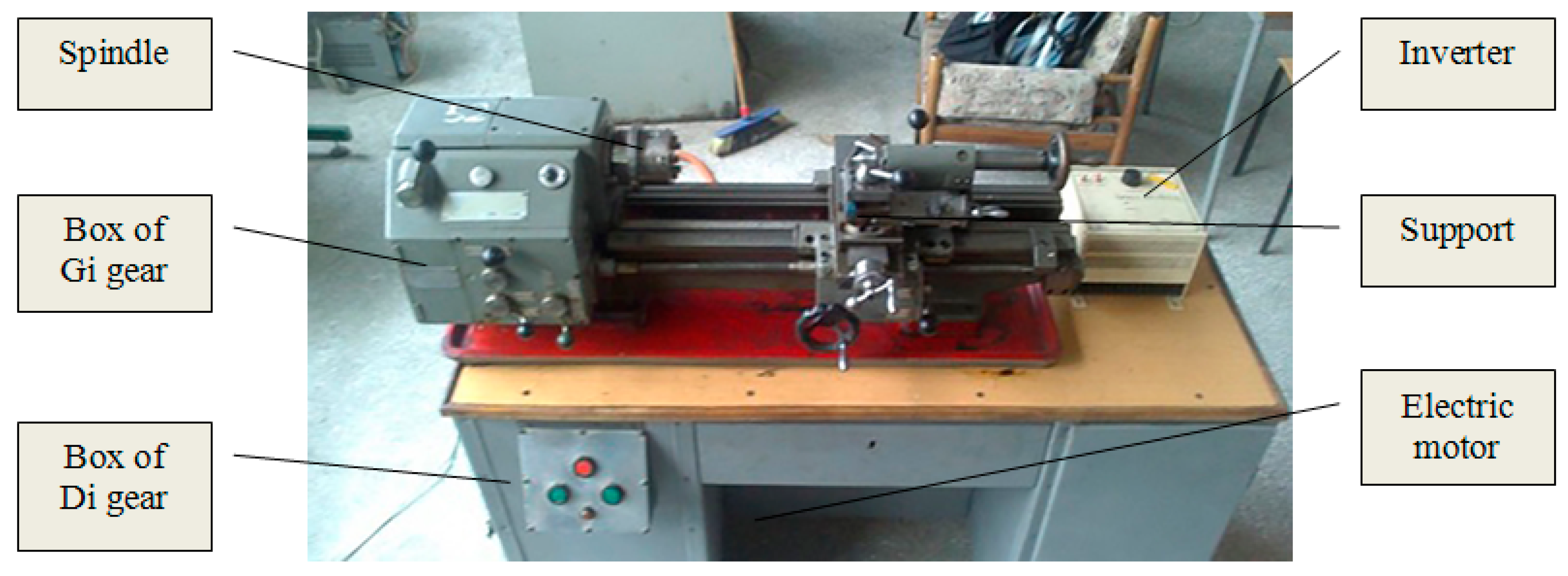
A TSB16 metalworking lathe (ZSZ Gorlice, Poland) in the workshop is shown in Figure 2. It houses a three-phase electric motor (P = 0.8 kW) combined with a two-stage belt drive and removable wheels that can be operated at 18 speeds. Key data for the lathe are shown in Table 2 (data for threading and lathe fasteners is omitted).
The three mechanical and manual feed rates of the lathe propelled by a belt-drive system are shown in Table 3. The three changes to the spindle drive speed of the lathe limit the choice of suitable cutting speeds with significant consequences for the optimum tool life of the cutting edge [34,35]; also optimum cutting speeds cannot be selected with a graded drive system. The recommended cutting speeds for different tool materials, workpiece materials, and machine tools are all listed in the DTR (technical instruction) of the TSB16 lathe [33].

2.3. Lathe-Drive Regulation with an Inverter

2.3.1. Lathe Power Transmission System Regulated with an Inverter

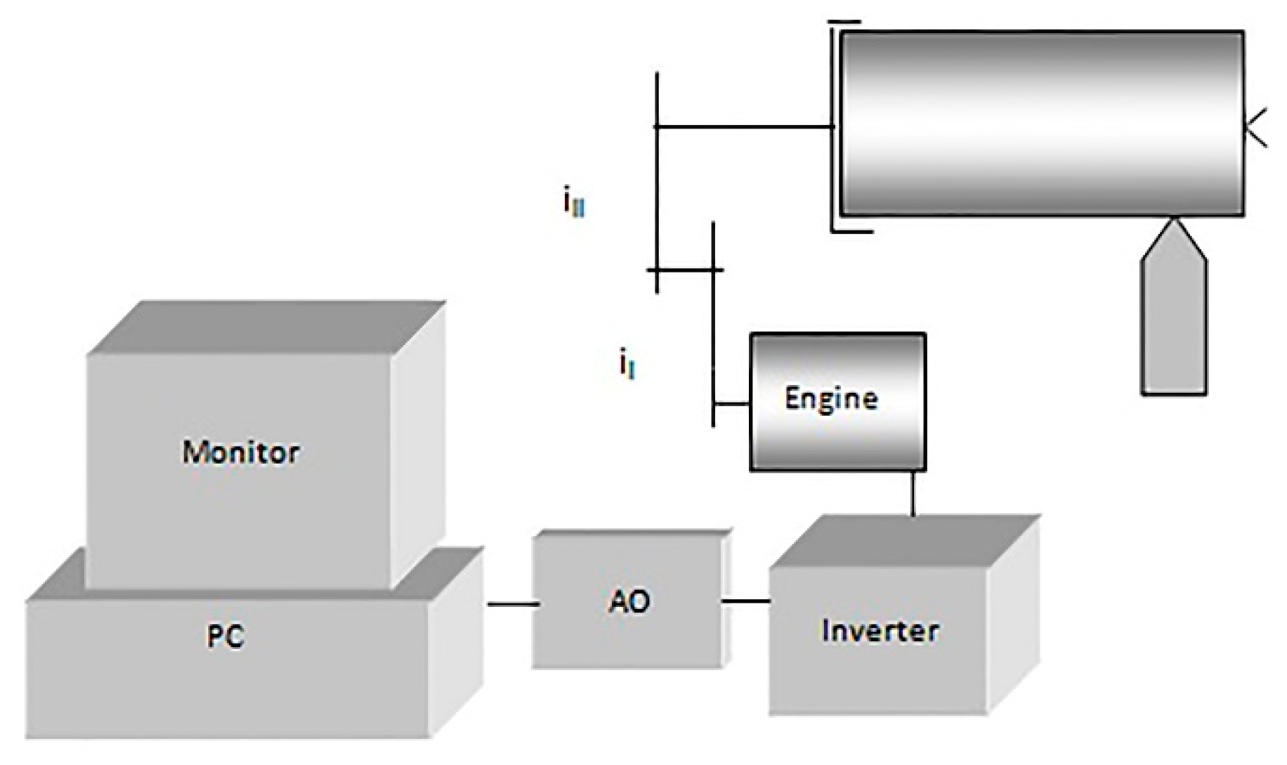
As a part of the proposed modernization of existing lathe systems, a continuously variable speed main transmission drive was developed using an inverter. A block diagram of the proposed system is presented in Figure 3.
The electric motor of the lathe was regulated with an AFREQVAR 100 (type PC1110) inverter, manufactured by OBR USN (Torun, Poland) with a capacity of 1.1 kW, as shown in Figure 4. This inverter converts 50 Hz AC 230V into three phases (3 × 380 V) with an adjustable frequency within the range of 0–120 Hz. It was manufactured in 2010.
According to the manufacturer’s description, we expect that in the speed range from 30–100%, the electric motor works with a constant torque equal to the rated torque of the electric motor, and in the speed range above the rated, the electric motor works at a constant power which is equal to the rated power of the electric motor.
Nowadays, the cost of a similar inverter LG/LS—1.5 KW 1F is approximately $150 [36]. The inverter AFREQVAR 100 was selected because it has sufficient power for the TSB16 metalworking lathe. A convenient feature of the inverter was that it generates three-phase current from single phase current. This also ensures the possibility of using a machine tool with the developed drive control if there is no access to a three-phase network.
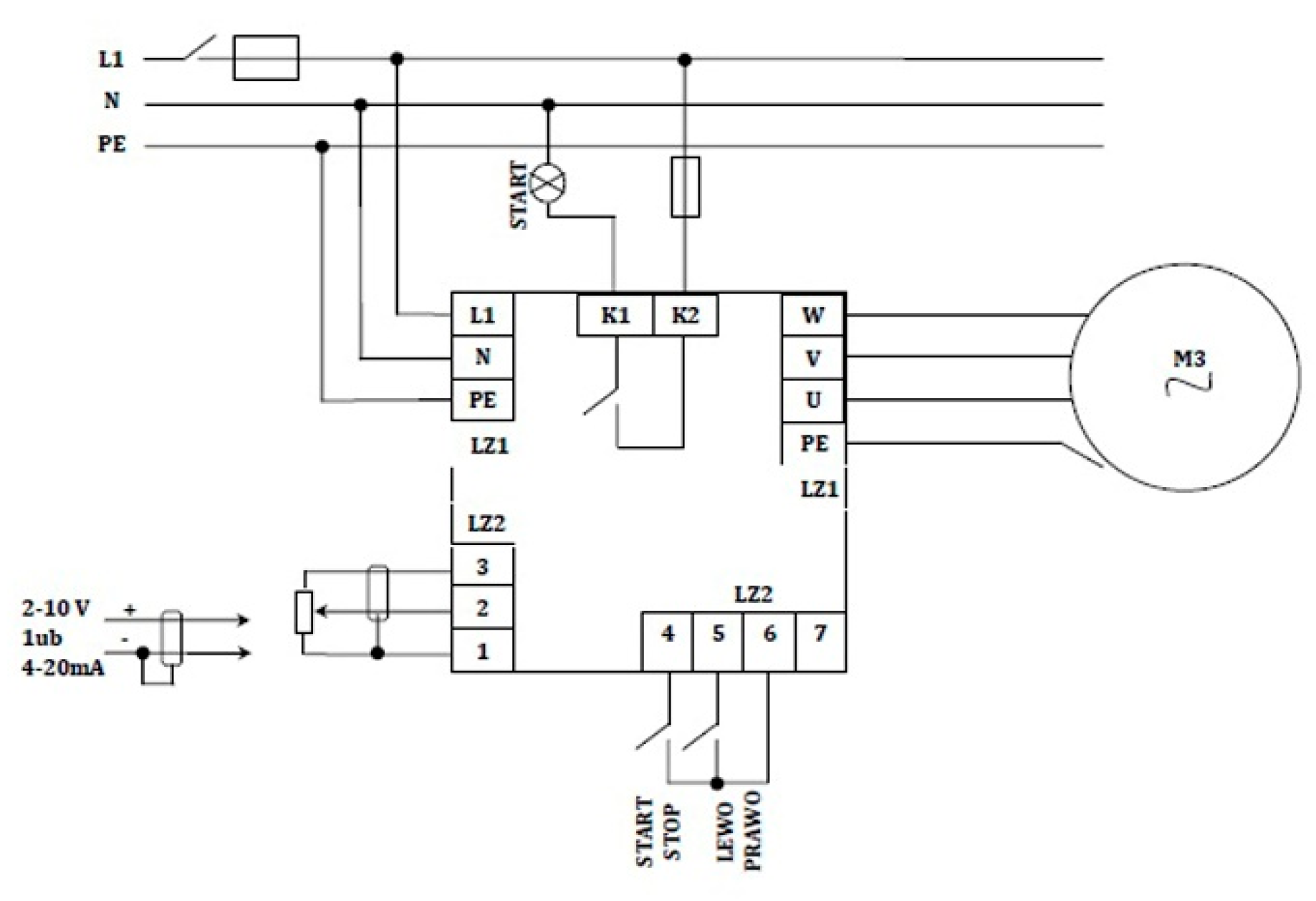
In a conventional setting mode, the knob of the inverter is used to regulate stepless manual speed control (Figure 4). The inverter may also be remotely controlled by using an electric signal - voltage 0–5 V or amperage 0–20 mV (Figure 5). This was also very important when choosing it for implementation.
Remote control of the inverter with an electric signal makes it possible to develop a computer control system. A voltage signal using an AO converter was proposed for remote control.
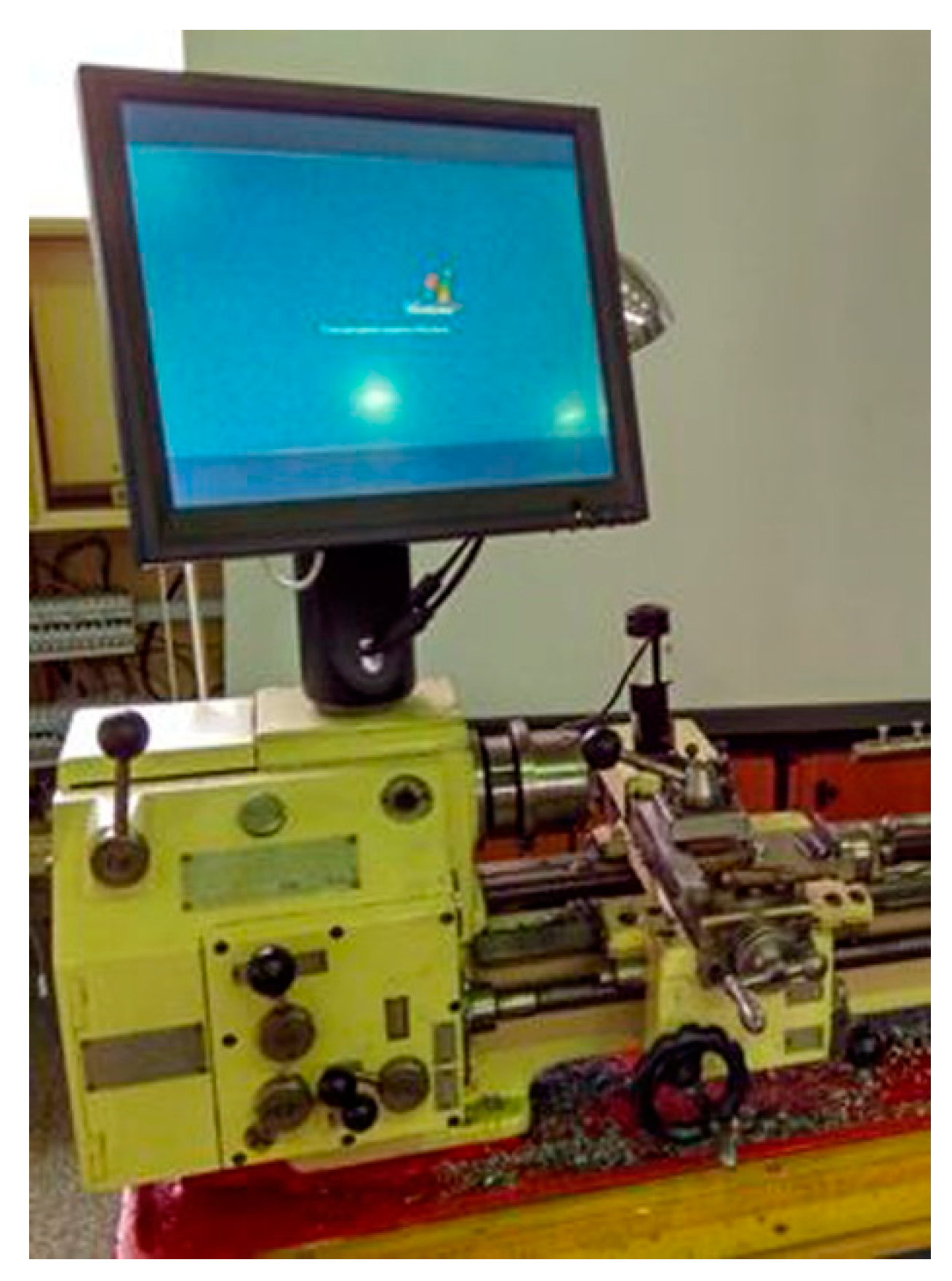
The control system uses a computer touch screen (Figure 6), which provides a convenient means of position control. The monitor will be positioned alongside the lathe once the lathe housing has been suitably adapted. The touch screen plays the role of human-machine-interface (HMI). Activation of the display in the upper part of the monitor presents the current lathe spindle speed. The control computer used was a Dell Optiplex GX520, 3.0 GHz with Win XP. This computer is equipped with many USB ports and LPT (local print terminal). This makes it suitable for control purposes.
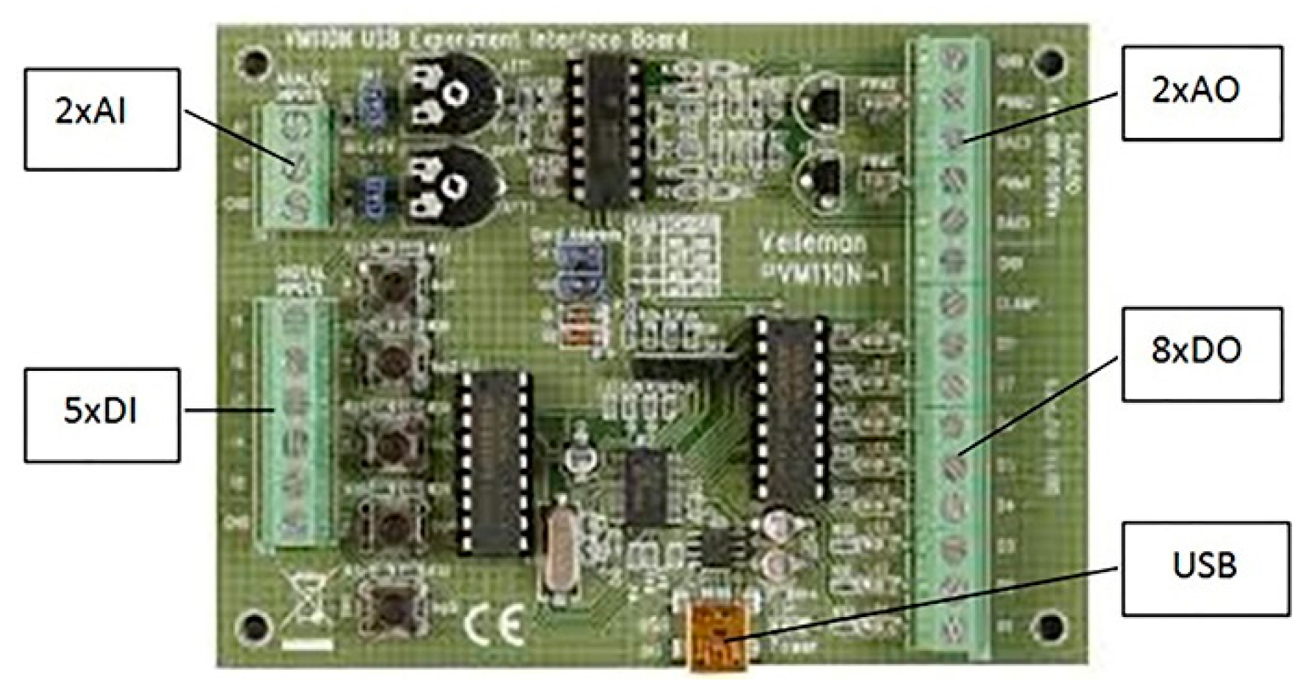
A special Velleman K8055 universal interface, as shown in Figure 7, was connected to the computer control system of the inverter. The interface was equipped with 2 × AO, 8 × DO, 2 × AI, and 5 × DI that cost $21.50. The scheme for using an AO port installed for remote control of the inverter is shown in Figure 4. Other inputs and outputs of the K8055 universal interface can also be used to create feedback control systems. For example, digital inputs can be used to measure the real spindle-speed value and to read the distance of the spindle from the spindle axis. These measurements are useful for adaptive control, which maintains the cutting speeds in proportion with diametrical variations while processing.

2.3.2. Spindle Rotation Using an Electric Power System with an Inverter

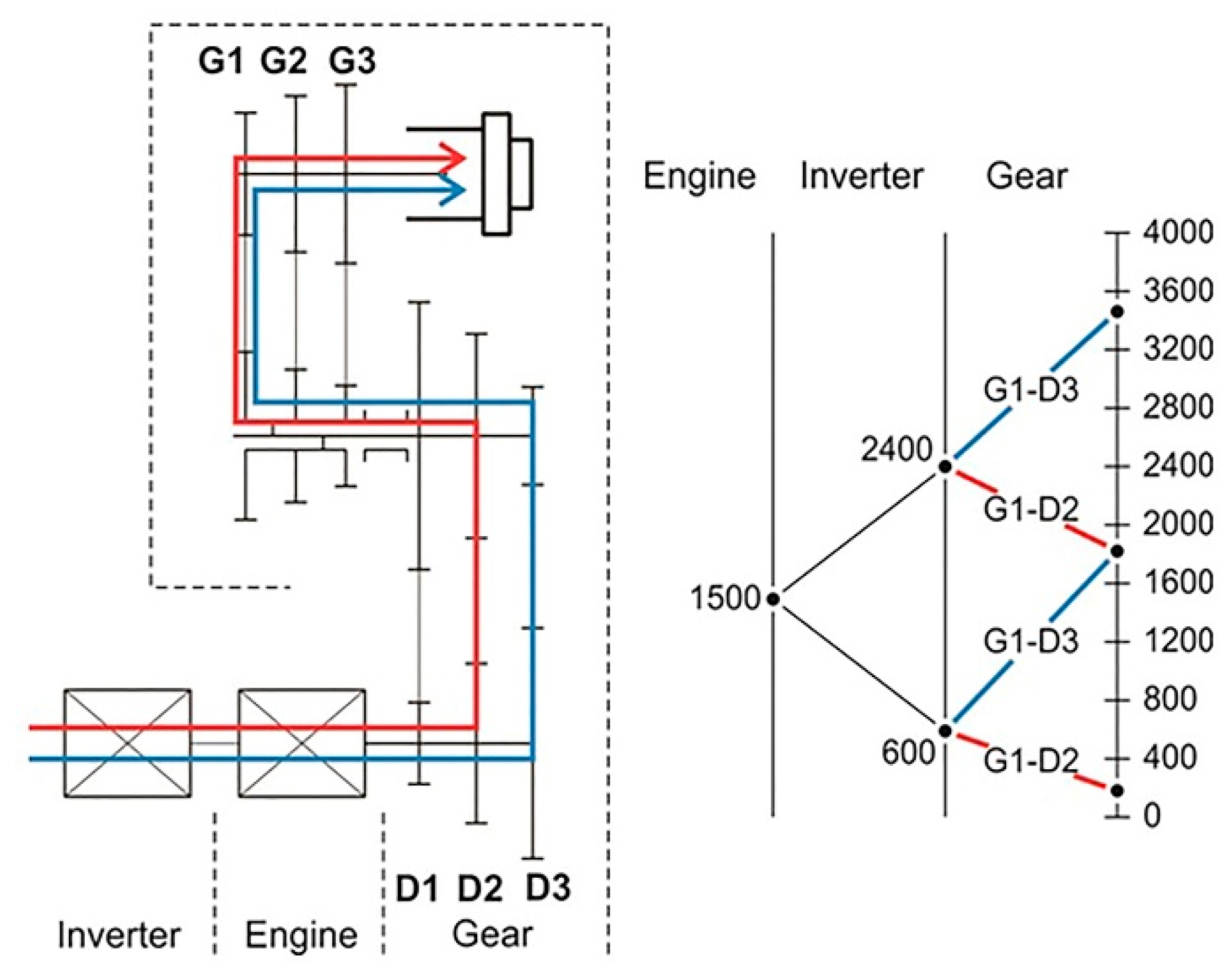
By connecting the inverter to the electric motor, stepless control of the speed is possible. The rotational speed may either be decreased or increased. An example of using an inverter for control of the TSB16 spindle is presented in Figure 8. The electric motor power that the inverter regulates is transmitted via the gearing to the lathe spindle drive. The arbitrarily adopted lower limit of the inverter was 20 Hz at an idling electric motor speed with appropriate fan cooling.
In the example that is presented here, the inverter control adjusts the main frequency within the range of 20 to 80 Hz to drive the entire range of lathe spindle rotations with only one gear change (Figure 8) in the electric motor. Fan cooling of the motor axis limits the range of low Hz values. The nominal speed of the electric motor design represents the limit on high speeds.
The lowest electric motor speed when connected to the inverter was 600 rpm and the maximum was 2400 rpm.

2.3.3. Machining Optimization Methodology

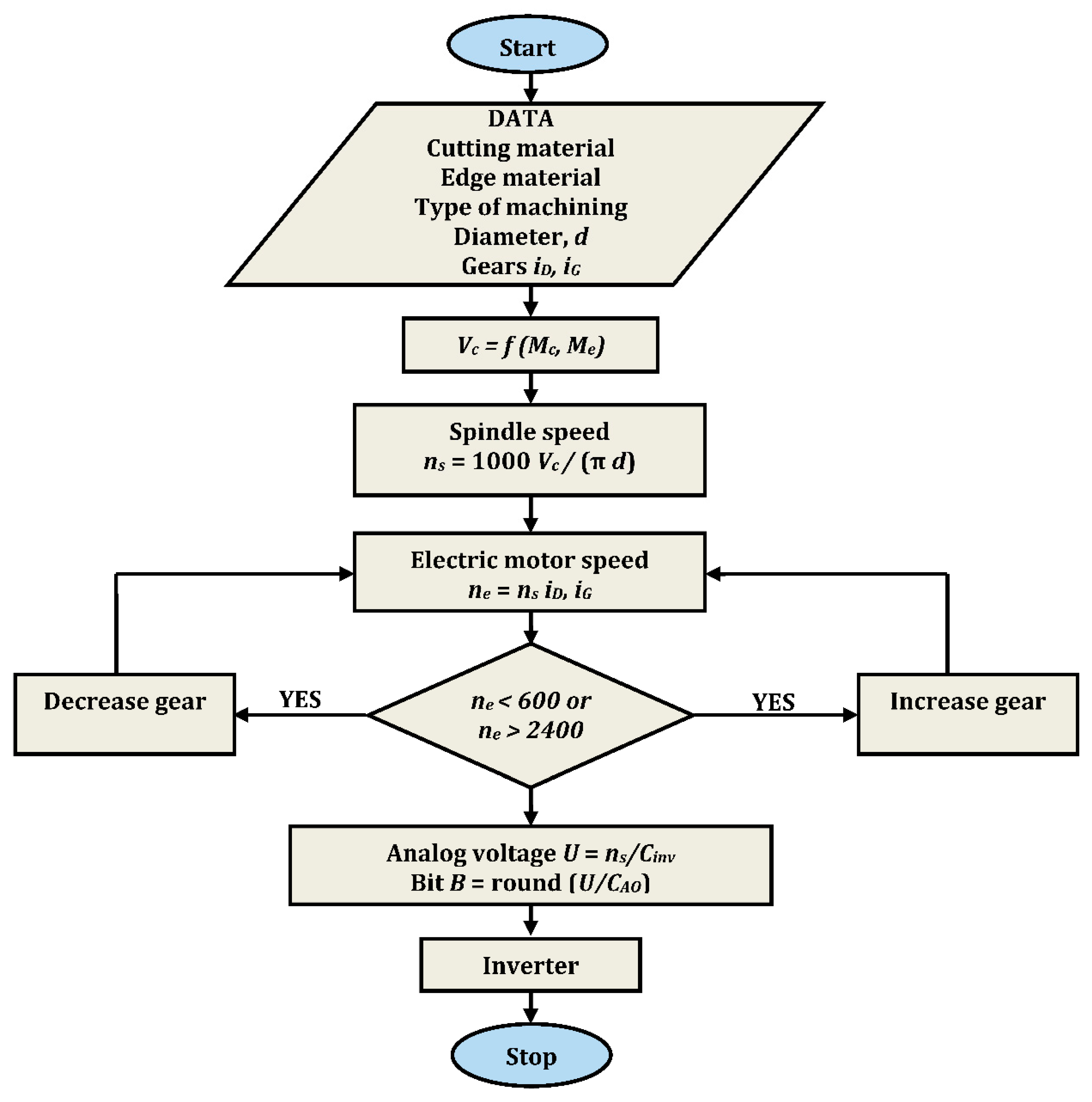
The use of the developed power system using an inverter was elaborated by a special methodology based on the limitations of the inverter control with the use of AO (Figure 1). To set the technological parameters, we needed to know the value of the cutting speed vc. This value is determined on the basis of the catalog information from the tool manufacturers for selected materials. The aim of the developed methodology was to optimally utilize the capabilities of the developed propulsion system, taking into account both the power supply of the motor by the inverter and the construction of a conventional drive system. The essence of the proposed hybrid drive system, considering it includes both a continuously variable speed control system for the electric motor and the existing gear ratios of the machine tool, was to ensure the possibility of machining at a wide range of cutting speeds and workpiece diameters. The basic assumption was to obtain a drive system with minimal use of the necessary gear changes. An algorithm written with specialized system-control software is presented in Figure 9.
The technological process data were applied in the algorithm to calculate both the cutting speed, vc, and the spindle rotation speed, ns, as well as to assess changes in the electric motor speed, when signals are sent to the inverter through an analog output control. If a signal is not sent, the system will eventually change gear.
The voltage value U is controlled on the basis of the initial calibration dependence of the inverter input voltage, following the scheme shown in (Figure 9):
U = ne/cinv
where ne is the electric motor speed and cinv is a proportionality coefficient for the inverter.
The inverter is controlled using an analog output controlled by an 8-bit converter. Hence the need to calculate the bit value B for sending numbers in the range of 0 to 255. It is calculated using the inverter input voltage U (1):
B = round(U/cAO),
where cAO is an AO proportionality coefficient.
However, due to the design of the electric motor and to avoid damaging the object, the maximum voltage that was applied equaled 3333 mV, which was sufficient to reach a current frequency of 80 Hz and an electric motor speed of 2400 rpm.

2.3.4. Special Software for Control System Using Inverter

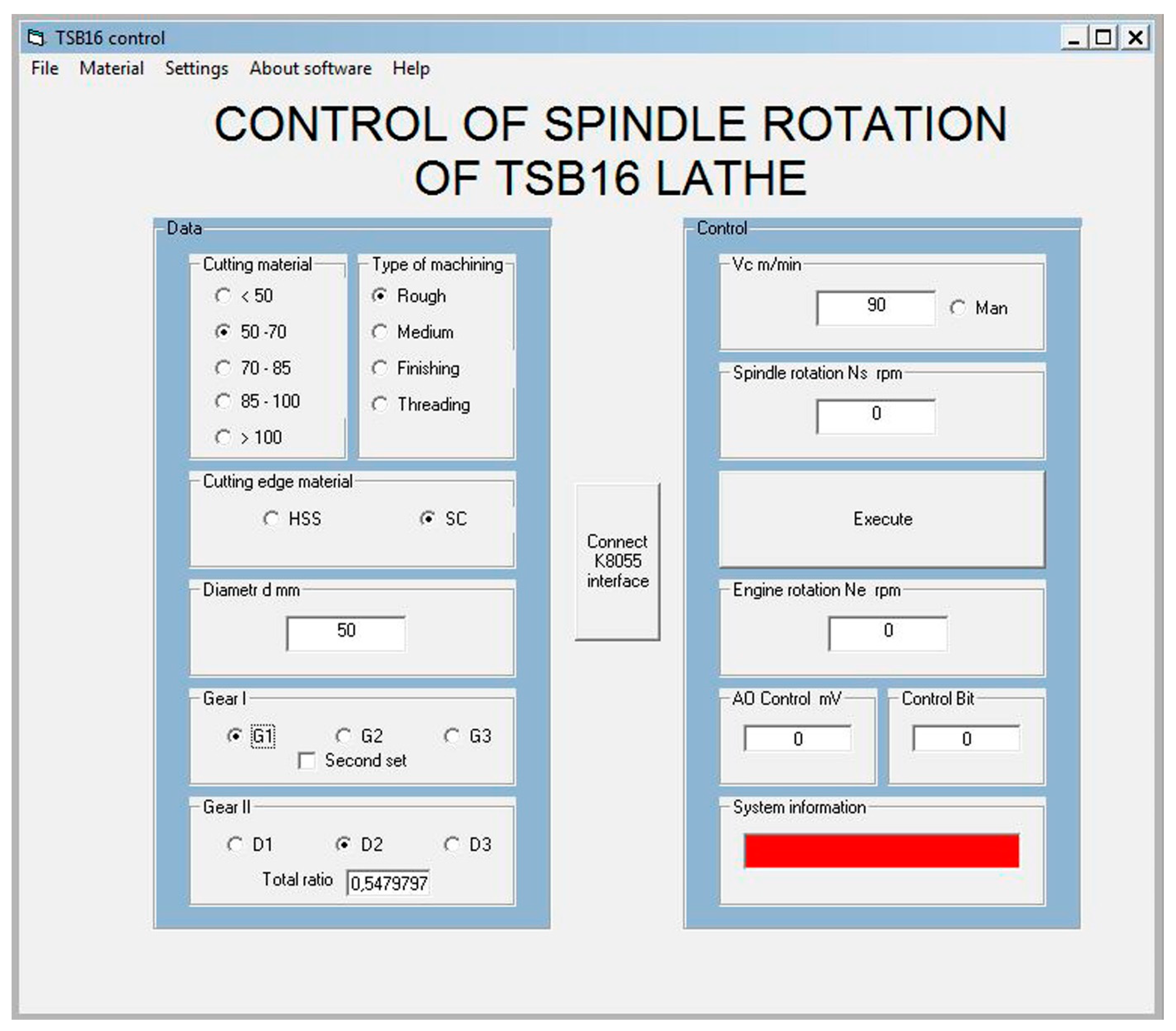
To control the developed system, the authors used an especially elaborated in Visual Basic (VB6) own software, Speed Control. The software that was developed uses objects that facilitate control over the computer interface. A screenshot of this software is shown in Figure 10. It is also possible to enter the cutting speed value manually. The size of the panel was adapted to the resolution used by the touch screen (768 × 1000 pixels).
The software contains the data from the lathe instructions, permitting the selection of cutting speeds for specific conditions including:
  • tool material,
  • workpiece material,
  • processing method (turning, boring et al.).
These data should be indicated in the input panel of the processing conditions. The software is equipped with information on the lathe gears ratios according to the kinematic diagram (Table 3). The actual sets of gears should be marked as first gear or second gear.
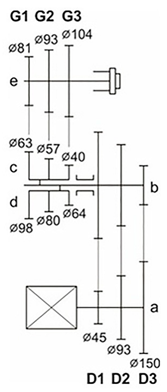
Hence, for easier notation (Table 3, Figure 8) for the electric motor gearing is:
  • Gi = second gear,
  • Di = first gear.
The index and the designation determine the location of the V-belt (along the spindle) from left to right. Gear ratios are stored in a data file (.csv) of the Speed Control software. Each change produces an updated record. There is also another database associated with the properties of the workpiece materials and the cutting edge that could be used. These alternatives are convenient because of steady progress in the field of materials for turning tools and their manufacture. The machine must be properly supported at the time of each (gear) change following the relevant software command.

3. Results and Discussion

Practical applications of the software confirmed the usefulness of the experiment. Here, we present:
  • Test results for the spindle speed control system,
  • Analysis of deviation in the conventional power system,
  • Analysis of deviation in the inverter-based power system,
  • Discussion of the results.

3.1. Tests of the Spindle Speed Control System

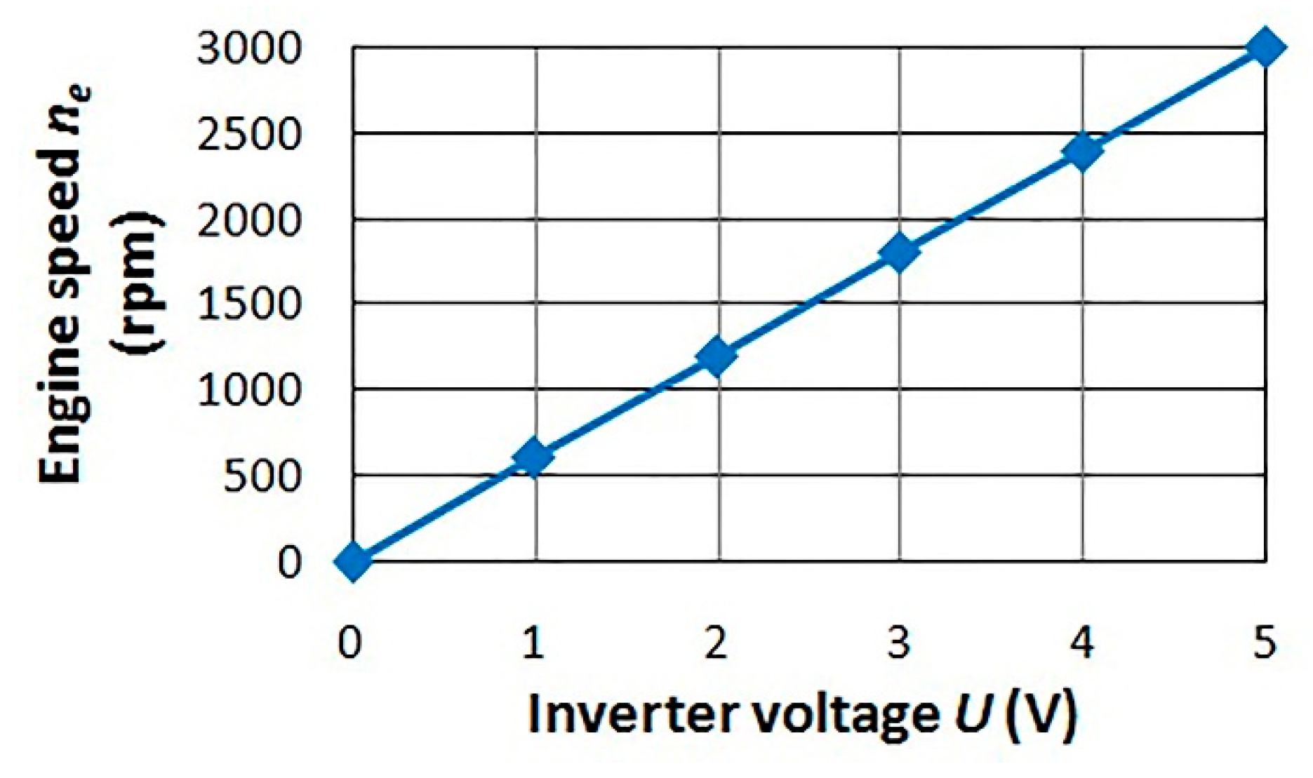
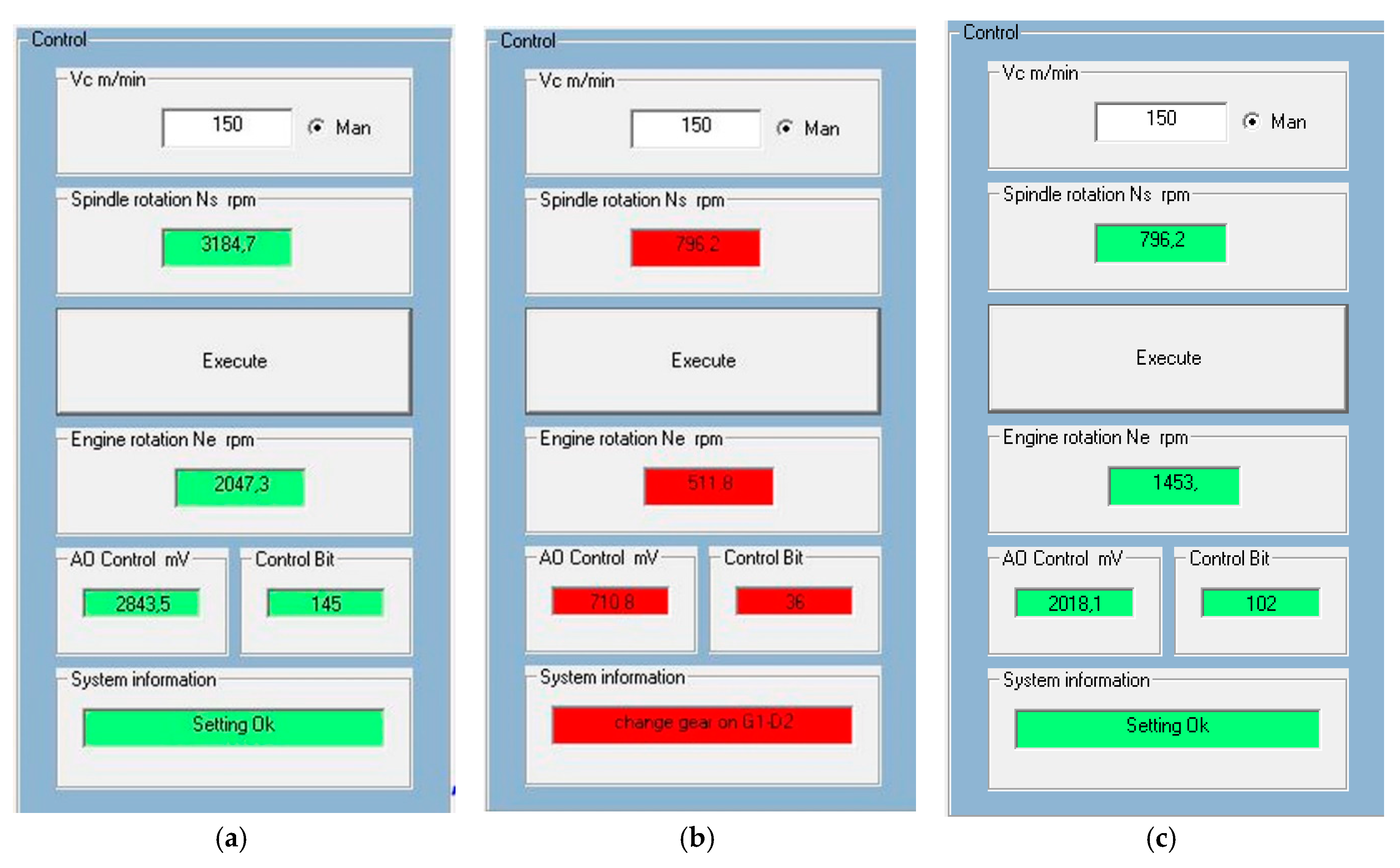
A calibration test was performed to control the electric motor speed using a voltage signal (Figure 11). It confirm proposed relation (2). The software program signals a gear change in order to obtain the desired cutting-speed control. An analog voltage signal is sent to the inverter control system combining the AO of the K8055 interface with the accuracy of an 8-bit converter (0 to 255 level). An example of the software answer for another input of d value and gear setting is presented in Figure 12. A single cutting-speed value, vc = 150 m/min was analyzed to compare the two solutions for the lathe power system: the conventional one and the inverter-based innovation.
The Speed Control software sends a signal to determine the inverter control voltage for the appropriate speed (Figure 12a). It also verifies the situations in which the gear ratio was not adapted (Figure 12b). After the system makes the proposed change of gear we get the message, “setting Ok” (Figure 12c).

3.2. Analysis of Deviation in the Conventional Power System

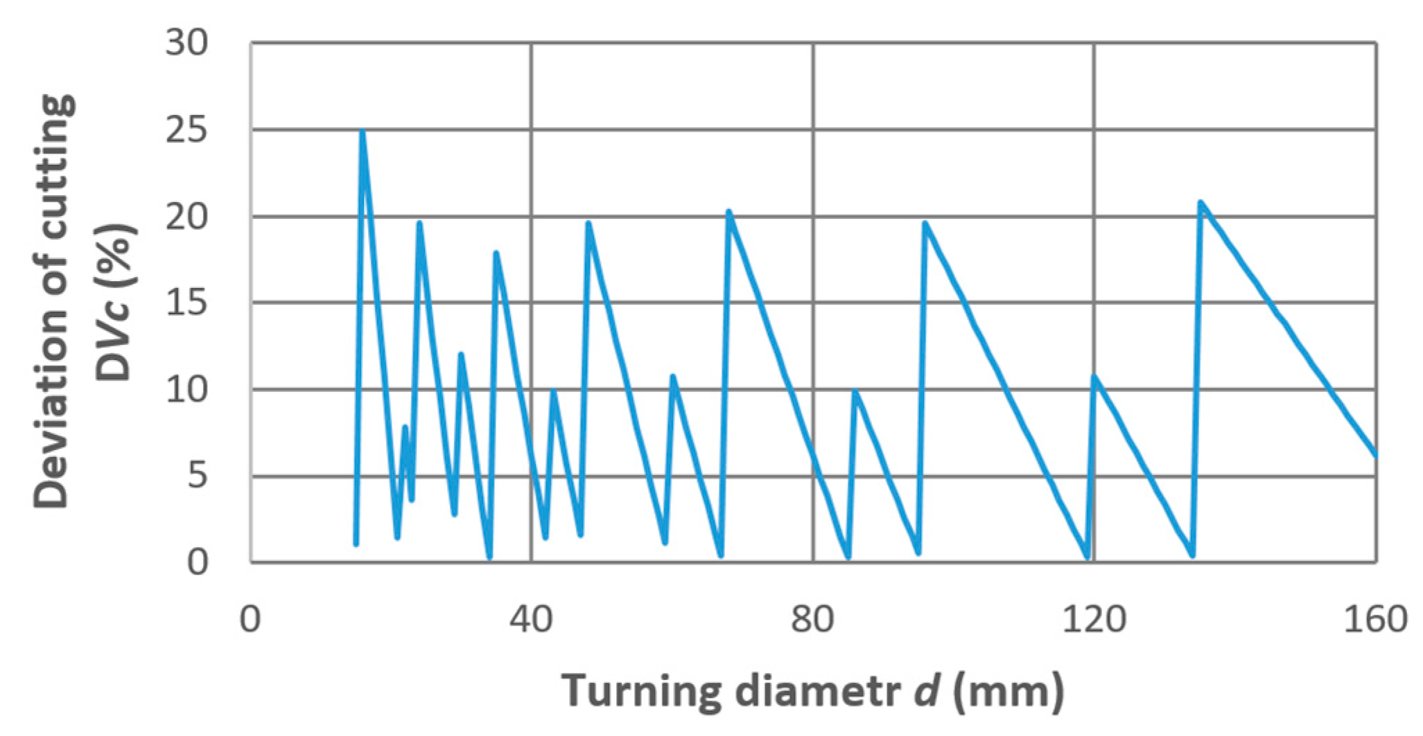
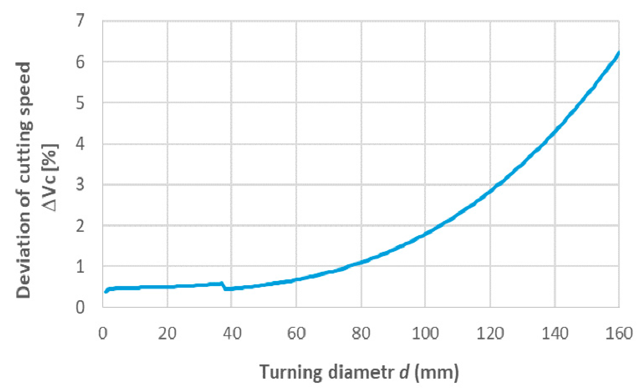
The analysis of deviation (Figure 13 and Figure 14) was done using real data on gearing and the above-mentioned vc value. In Figure 13, the influence of the workpiece diameter on the cutting-speed value that can be achieved using the conventional power system with gears is shown. There are significant relative-error values that show incremental changes because the gear ratios are conventional with a limited number of degrees. These results were compared with the new solution for the power system.
The results show that a change of gear in the electric motor is necessary in many cases to change the spindle speed of the lathe when using the conventional drive system. Using this solution, we obtain a significant difference between the optimum cutting speed and the cutting speed that is obtained in practice (Figure 14). The error is introduced at the time of the gear change that is needed at a given point in time to achieve the required vc.

3.3. Analysis of Deviation in the Inverter Based Power System

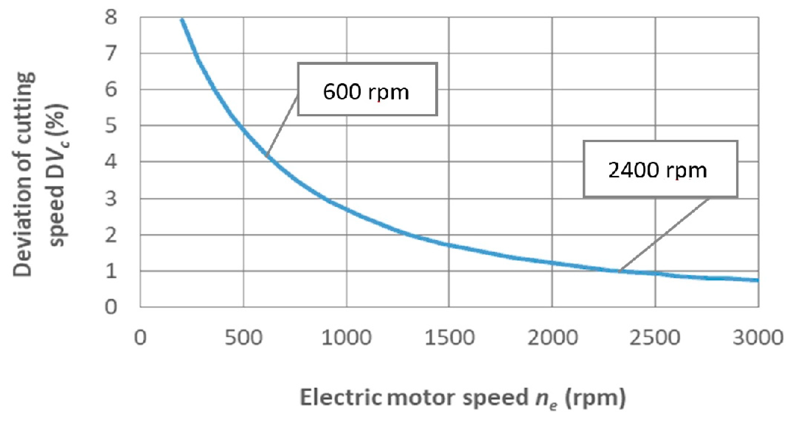
As the inverter is controlled using an 8-bit converter, the accuracy of the electric motor speed control will depend on the output voltage. The minimal value of a step is 19.608 mV for each bit, as presented in Table 1. The graph presented in Figure 15 is based on the relation between the deviation of the electric motor speed controlled using the AO converter and its deviation is dependent on the value of the controlled voltage. It was shown (Figure 15) that due to the use of digital inverter control, the error depends on the output voltage for lower voltage values and the deviation increases up to 8%. However, for speeds above 600 rpm, the error value will drop below 4% and obtain a value below 2% for a nominal speed of 1500 rpm and for speeds of 2400 rpm 1%.
A further example of using the inverter system for electric motor speed control is presented in Figure 16. Machining within the full range of lathe speeds, presented as the diameters of the lathe workpiece, was done with only two gears (G1-D3 and G1-D2). The thicker the diameter, the lower the electric motor-speed values, hence, the deviation increased with the diameter as shown in the graph presented in Figure 17.

3.4. Discussion

The developed low-cost control system enabled the use of stepless speed control with the accuracy as indicated in the analysis.
The results showed that the use of an automated spindle rotation control provides a stable cutting-speed. In conventional systems, there is sometimes a need to reduce the cutting speed by 20%. By using an inverter for speed control of the electric motor, it was possible to achieve stepless control of the spindle rotation.
As shown in Figure 16 and Figure 17, machining within the full range of lathe speeds was done with only two gears (G1-D3 and G1-D2). The deviation increased with the diameter, as shown in the graph presented in Figure 17.
The deviation in accuracy was only in excess of 4% at low electric motor speeds of 600 rpm, due to the 8-bit converter controller. The error value dropped below 4% to reach a value below 2% for a nominal speed of 1500 rpm and for speeds of 2400 rpm 1%.
This level of error reduces the processing efficiency and significantly changes the cutting conditions, which may in turn have an impact on the surface condition and cutting-edge durability.
Further improvements in the present system can be made by applying feedback loops to enable maintenance of the set speed based on the actual spindle speed.
In addition, automatic measurement of the workpiece diameter or the distance of the tip of the cutting edge from the center of rotation is advisable for automatic selection of the speed for a previously established cutting-tool material and a workpiece with a preset optimum cutting speed.
It should also be mentioned that further improvements to these machines can be introduced through modernization of the feed systems with a servo-drive type or by using a step motor; the servo-drive is especially convenient due to its low cost.
The cost of the control system, without taking into account the cost of the computer was approximately $ 175 with power of 1.5 kW [36]. The ATMEGA microprocessor may also be used instead of a computer. Only the price of the inverter changes with a higher drive power. For example, the cost of LG/LS—7.5 KW 3F, SV075IG5A-4 inverter is $ 465 [37]; far less expensive than CNC machines with infinitely variable speed controls.
The stepless speed control enables optimum cutting speeds to be selected based on the material type of the edge and the material to be machined for each workpiece diameter. Reported literature and practice allow us to achieve the desired edge durability [30,32,38] and surface condition [27,39,40]. Achieving a constant cutting speed is particularly desirable in turning faces with a continuous change in the turning diameter. The developed configuration is adapted to the development of continuous on-line control of the machining speed, which requires the equipment to be equipped with a measurement system for the machining diameter.

4. Conclusions

In this paper, the problem of achieving an optimum cutting speed for each workpiece diameter with a conventional lathe was approached by coupling an inverter to the lathe-drive system. The method that has been presented can achieve infinitely variable cutting speeds by remodeling the propulsion system. The proposed low-cost system is simple and intuitive to use, and is manually controlled by the frequency reference using the potentiometer to obtain the desired speed.
An electronic system has been developed for the analysis of the necessary spindle rotation speed and control of the inverter voltage using an electric signal. In turn, optimal tool life and the required surface roughness values can more easily be achieved. Moreover, the system can significantly increase the quality of the cutting process.
The results have shown that the use of automated spindle rotation control provides a stable cutting-speed value. In conventional systems, there is sometimes a need to reduce the cutting speed by 20%. By using an inverter for speed control of the electric motor, it has been possible to achieve stepless control of the spindle rotation.
The deviation in accuracy is only in excess of 4% at low electric motor speeds of 600 rpm, due to the 8-bit converter controller. The error value will drop below 4% to reach a value below 2% for a nominal speed of 1500 rpm and to 1% for speeds of 2400 rpm.
This level of error reduces the processing efficiency and significantly changes the cutting conditions, which may in turn have an impact on the surface condition and cutting-edge durability.
Further improvements to the present system can be made by applying feedback loops to enable maintenance of the set speed based on the actual spindle speed.
In addition, automatic measurement of workpiece diameter or the distance of the tip of the cutting edge from the center of rotation is advisable for automatic selection of the speed for a previously established cutting-tool material and a workpiece with a preset optimum cutting speed.
It should also be mentioned that further improvements to these machines can be introduced through modernization of the feed systems with a servo-drive type or by using a step motor; the servo-drive is especially convenient due to its low cost.
The proposed solution can be interesting to handle legacy and reliable equipment.

Author Contributions

Conceptualization, T.M., T.P. and D.Y.P.; Methodology, T.M., T.P. and D.Y.P.; Software, T.M.; Validation, T.M. and T.P.; Formal Analysis, T.M. and T.P.; Investigation, T.M., T.P. and J.Z.; Resources, T.M., T.P. and J.Z.; Data Curation, T.M., T.P.; Writing-Original Draft Preparation, T.M., T.P., D.Y.P., K.P. and J.Z.; Writing-Review & Editing, T.M., D.Y.P., M.M., K.P., G.K., M.K.G. and J.Z.; Visualization, T.M., T.P., D.Y.P., M.M., M.K.G.; Supervision, T.M., D.Y.P., M.M., G.K., M.K.G. and J.Z.; Project Administration, T.M. and J.Z.; Funding Acquisition, D.Y.P. and G.K.

Funding

The study was supported under Act 211 of the Government of the Russian Federation, contract Nr. 02.A03.21.0011.

Conflicts of Interest

The authors declare no conflict of interest.

Nomenclature

apcutting depth (mm)
vccutting speed (m/min)
dactual value of turning diameter (mm)
dbturning diameter over bed (mm)
dsturning diameter over support (mm)
Lturning length (mm)
nsspindle speed (rpm)
neelectric motor speed (rpm)
Pelectric motor power (kW)
MCcutting material
MTtool material
Uanalog voltage (V)
AOanalog output converter
aeAOabsolute error of AO (mV)
reAOrelative error of AO (%)
HMIHuman-Machine-Interface
Difirst gear
Gisecond gear
cinv, cAOproportionality coefficients

References

  1. Bharathi, R.S.; Baskar, N. Particle swarm optimization technique for determining optimal machining parameters of different work piece materials in turning operation. Int. J. Adv. Manuf. Technol. 2011, 54, 445–463. [Google Scholar] [CrossRef]
  2. Fernández-Abia, A.I.; Barreiro, J.; López de Lacalle, L.N.; Martínez, S. Effect of very high cutting speeds on shearing, cutting forces and roughness in dry turning of austenitic stainless steels. Int. J. Adv. Manuf. Technol. 2011, 57, 61–71. [Google Scholar] [CrossRef]
  3. Dimla, D.E. The impact of cutting conditions on cutting forces and vibration signals in turning with plane face geometry inserts. J. Mater. Process. Technol. 2004, 155–156, 1708–1715. [Google Scholar] [CrossRef]
  4. Brožek, M. Cutting conditions optimization when turning overlays. J. Mater. Process. Technol. 2005, 168, 488–495. [Google Scholar] [CrossRef]
  5. Diniz, A.E.; Micaroni, R.; Hassui, A. Evaluating the effect of coolant pressure and flow rate on tool wear and tool life in the steel turning operation. Int. J. Adv. Manuf. Technol. 2010, 50, 1125–1133. [Google Scholar] [CrossRef]
  6. Urbikain, G.; López De Lacalle, L.N.; Fernández, A. Regenerative vibration avoidance due to tool tangential dynamics in interrupted turning operations. J. Sound. Vib. 2014, 333, 3996–4006. [Google Scholar] [CrossRef]
  7. Artamonov, E.V.; Vasil’ev, D.V. Determining the optimal cutting speed in turning by composite cutters on the basis of the chip. Russ. Eng. Res. 2014, 34, 404–405. [Google Scholar] [CrossRef]
  8. Nikolaenko, A.A. Thermodynamic model of high-speed turning. Russ. Eng. Res. 2015, 35, 339–343. [Google Scholar] [CrossRef]
  9. Anukhin, I.V.; Lyubomudrov, S.A.; Murashkin, S.L. Thermal imaging in selecting the cutting conditions for high-temperature intermetallic alloys. Russ. Eng. Res. 2015, 35, 544–548. [Google Scholar] [CrossRef]
  10. Garg, A.; Lam, J.S.L.; Gao, L. Power consumption and tool life models for the production process. J. Clean. Prod. 2016, 131, 754–764. [Google Scholar] [CrossRef]
  11. McParland, D.; Baron, S.; O’Rourke, S.; Dowling, D.; Ahearne, E.; Parnell, A. Prediction of tool-wear in turning of medical grade cobalt chromium molybdenum alloy (ASTM F75) using non-parametric Bayesian models. J. Intell. Manuf. 2017. [Google Scholar] [CrossRef]
  12. Johansson, D.; Hägglund, S.; Bushlya, V.; Ståhl, J.-E. Assessment of Commonly used Tool Life Models in Metal Cutting. Procedia Manuf. 2017, 11, 602–609. [Google Scholar] [CrossRef]
  13. Arruda, É.M.; Brandão, L.C. Performance study of multilayer carbide tool in high-speed turning of API 5L X70 pipeline steel using a cold air system. Int. J. Adv. Manuf. Technol. 2018, 94, 85–103. [Google Scholar] [CrossRef]
  14. Prasad, B.S.; Prabha, K.A.; Ganesh Kumar, P.V.S. Condition monitoring of turning process using infrared thermography technique—An experimental approach. Infrared Phys. Technol. 2017, 81, 137–147. [Google Scholar] [CrossRef]
  15. Mia, M.; Dhar, N.R. Prediction of surface roughness in hard turning under high pressure coolant using Artificial Neural Network. Measurement 2016, 92, 464–474. [Google Scholar] [CrossRef]
  16. Tanikić, D.; Marinković, V. Modelling and optimization of the surface roughness in the dry turning of the cold rolled alloyed steel using regression analysis. J. Braz. Soc. Mech. Sci. Eng. 2012, 34, 41–48. [Google Scholar] [CrossRef]
  17. Mia, M.; Dhar, N.R. Modeling of Surface Roughness Using RSM, FL and SA in Dry Hard Turning. Arab. J. Sci. Eng. 2018, 43, 1125–1136. [Google Scholar] [CrossRef]
  18. Venkata Rao, K.; Murthy, B.S.N.; Mohan Rao, N. Cutting tool condition monitoring by analyzing surface roughness, work piece vibration and volume of metal removed for AISI 1040 steel in boring. Measurement 2013, 46, 4075–4084. [Google Scholar] [CrossRef]
  19. Günay, M.; Yücel, E. Application of Taguchi method for determining optimum surface roughness in turning of high-alloy white cast iron. Measurement 2013, 46, 913–919. [Google Scholar] [CrossRef]
  20. Mia, M. Prediction and optimization of surface roughness in minimum quantity coolant lubrication applied turning of high hardness steel. Measurement 2018, 118, 43–51. [Google Scholar] [CrossRef]
  21. Khan, S.A.; Soo, S.L.; Aspinwall, D.K.; Sagec, C.; Hardend, P.; Fleminge, M.; White, A.; M’Saoubi, R. Tool wear/life evaluation when finish turning Inconel 718 using PCBN tooling. Procedia CIRP 2012, 1, 283–288. [Google Scholar] [CrossRef]
  22. Özbek, N.A.; Çiçek, A.; Gülesin, M.; Özbek, O. Investigation of the effects of cryogenic treatment applied at different holding times to cemented carbide inserts on tool wear. Int. J. Mach. Tools Manuf. 2014, 86, 34–43. [Google Scholar] [CrossRef]
  23. Zou, B.; Zhou, H.; Huang, C.; Xu, K.; Wang, J. Tool damage and machined-surface quality using hot-pressed sintering Ti(C7N3)/WC/TaC cermet cutting inserts for high-speed turning stainless steels. Int. J. Adv. Manuf. Technol. 2015, 79, 197–210. [Google Scholar] [CrossRef]
  24. Jurkovic, Z.; Cukor, G.; Brezocnik, M.; Brajkovic, T. A comparison of machine learning methods for cutting parameters prediction in high speed turning process. J. Intell. Manuf. 2018, 29, 1683–1693. [Google Scholar] [CrossRef]
  25. Orra, K.; Choudhury, S.K. Development of flank wear model of cutting tool by using adaptive feedback linear control system on machining AISI D2 steel and AISI 4340 steel. Mech. Syst. Signal Process. 2016, 81, 475–492. [Google Scholar] [CrossRef]
  26. Mia, M.; Khan, M.A.; Dhar, N.R. High-pressure coolant on flank and rake surfaces of tool in turning of Ti-6Al-4V: Investigations on surface roughness and tool wear. Int. J. Adv. Manuf. Technol. 2017, 90, 1825–1834. [Google Scholar] [CrossRef]
  27. Abbas, A.T.; Pimenov, D.Y.; Erdakov, I.N.; Mikolajczyk, T.; El Danaf, E.A.; Taha, M.A. Minimization of turning time for high-strength steel with a given surface roughness using the Edgeworth-Pareto optimization method. Int. J. Adv. Manuf. Technol. 2017, 93, 2375–2392. [Google Scholar] [CrossRef]
  28. Rogante, M. Wear characterisation and tool performance of sintered carbide inserts during automatic machining of AISI 1045 steel. J. Mater. Process. Technol. 2009, 209, 4776–4783. [Google Scholar] [CrossRef]
  29. Babouri, M.K.; Ouelaa, N.; Djebala, A. Experimental study of tool life transition and wear monitoring in turning operation using a hybrid method based on wavelet multi-resolution analysis and empirical mode decomposition. Int. J. Adv. Manuf. Technol. 2016, 82, 2017–2028. [Google Scholar] [CrossRef]
  30. Mikołajczyk, T.; Nowicki, K.; Bustillo, A.; Pimenov, D.Y. Predicting tool life in turning operations using neural networks and image processing. Mech. Syst. Signal Process. 2018, 104, 503–513. [Google Scholar] [CrossRef]
  31. Aramesh, M.; Attia, M.H.; Kishawy, H.A.; Balazinski, M. Estimating the remaining useful tool life of worn tools under different cutting parameters: A survival life analysis during turning of titanium metal matrix composites (Ti-MMCs). CIRP J. Manuf. Sci. Technol. 2016, 12, 35–43. [Google Scholar] [CrossRef]
  32. Mikolajczyk, T.; Fas, T.; Klodowski, A.; Matuszewski, M.; Olaru, A.; Olaru, S. Computer Aided System for Superfinishing Process Control. Procedia Technol. 2016, 22, 48–54. [Google Scholar] [CrossRef]
  33. Centralnego Biura Konstrukcyjnego Obrabiarek w Pruszkowie. Dokumentacja Techniczno-Ruchowa Tokarki TSB16; Technical Manual of TSB16 Lathe; CBKO: Pruszków, Poland, 1971. (In Polish) [Google Scholar]
  34. Grzesik, W. Advanced Machining Processes of Metallic Materials: Theory, Modelling and Applications; Elsevier: Amsterdam, The Netherlands, 2008. [Google Scholar]
  35. Przybylski, L. Strategia doboru warunków obróbki współczesnymi narzędziami. In The Strategy of Machining Conditions Selection Using Modern Tools; Politechnika Krakowska: Kraków, Poland, 2000. (In Polish) [Google Scholar]
  36. Falowniki. Available online: https://www.sklepfalowniki.pl/falownik-sv015ic5-1f-15kw.html (accessed on 18 November 2017).
  37. Falowniki. Available online: https://www.sklepfalowniki.pl/falowniki-lg-s100-3f.html (accessed on 18 November 2017).
  38. Pimenov, D.Y. The effect of the rate flank wear teeth face mills on the processing. J. Frict. Wear 2013, 34, 156–159. [Google Scholar] [CrossRef]
  39. Abbas, A.T.; Pimenov, D.Y.; Erdakov, I.N.; Taha, M.A.; Soliman, M.S.; El Rayes, M.M. ANN surface roughness optimization of AZ61 magnesium alloy finish turning: Minimum machining times at prime machining costs. Materials 2018, 11, 808. [Google Scholar] [CrossRef] [PubMed]
  40. Abbas, A.T.; Pimenov, D.Y.; Erdakov, I.N.; Taha, M.A.; El Rayes, M.M.; Soliman, M.S. Artificial intelligence monitoring of hardening methods and cutting conditions and their effects on surface roughness, performance, and finish turning costs of solid-state recycled aluminum alloy 6061 chips. Metals 2018, 8, 394. [Google Scholar] [CrossRef]
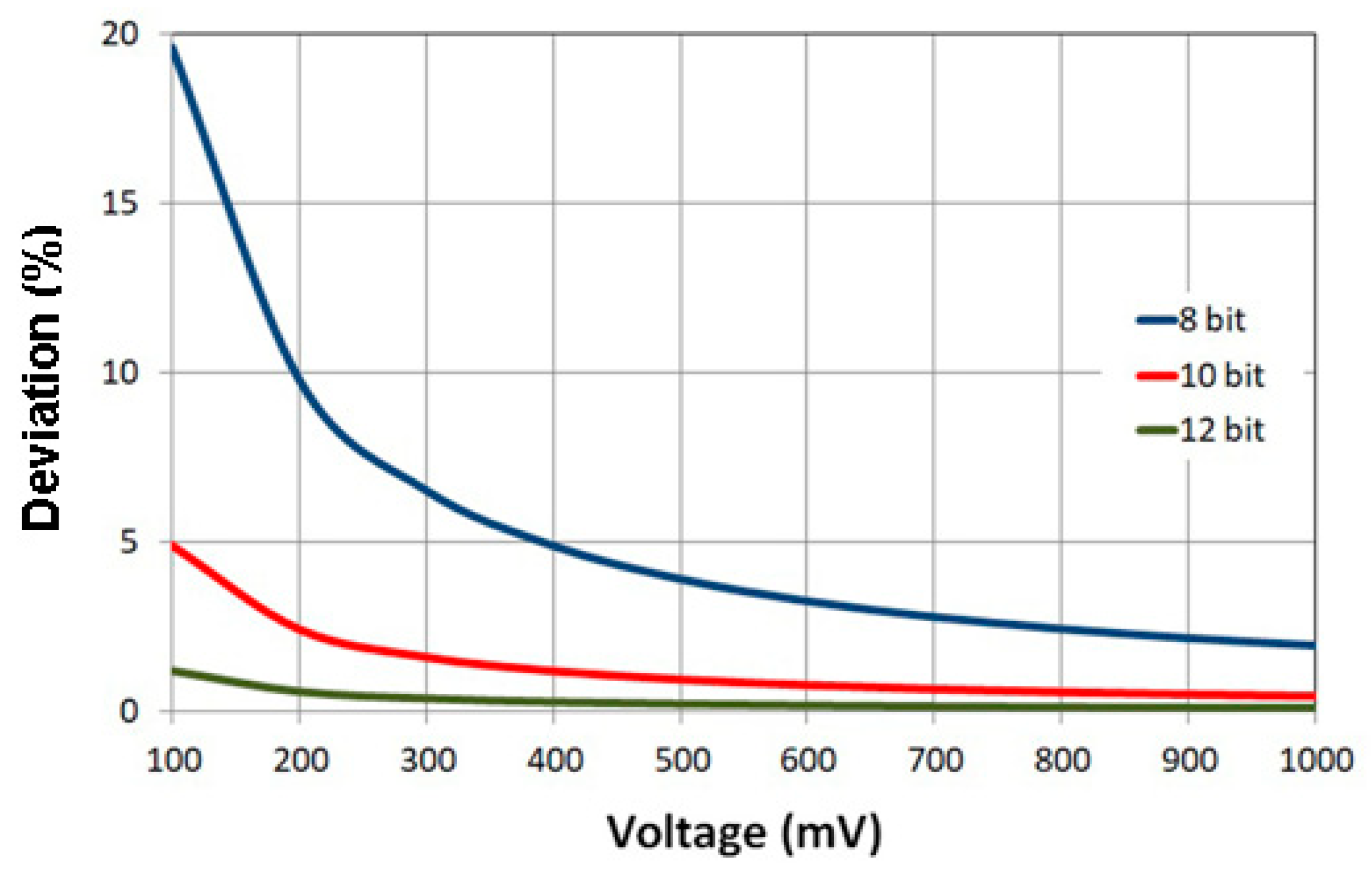
Figure 1. Effect of voltage signal for another resolution of the AO converter on deviation—reAO.
Applsci 09 00012 g001
Figure 2. View of a TSB16 lathe with inverter.
Applsci 09 00012 g002
Figure 3. Schematic diagram of lathe-spindle speed control system.
Applsci 09 00012 g003
Figure 4. FREQVAR 1000 inverter.
Applsci 09 00012 g004
Figure 5. Schematic control system of a FREQVAR 1000 inverter.
Applsci 09 00012 g005
Figure 6. TSB 16 equipped with touch screen.
Applsci 09 00012 g006
Figure 7. Velleman K8055 interface.
Applsci 09 00012 g007
Figure 8. Example of inverter-controlled spindle speeds.
Applsci 09 00012 g008
Figure 9. A simplified algorithm of a cutting-speed control system using an inverter.
Applsci 09 00012 g009
Figure 10. View of the form of the Speed Control software: designation of spindle speed.
Applsci 09 00012 g010
Figure 11. The impact of inverter voltage on electric motor speed control.
Applsci 09 00012 g011
Figure 12. Examples of software messages (the vc = 150 m/min value was entered manually): (a) system setting for d = 15 mm, G1-D3; (b) the system sends a message on the need for a gear change for d = 60 mm, G1-D3; (c) system setting after gear change for d = 60 mm, G1-D2.
Applsci 09 00012 g012
Figure 13. Influence of workpiece diameter on the real value of the cutting speed for the conventional power system of a TSB 16 lathe for a target cutting speed of vc = 150 m/min.
Applsci 09 00012 g013
Figure 14. Effect of workpiece diameter on the deviation in cutting speed for the conventional power system of a TSB 16 lathe at vc = 150 m/min.
Applsci 09 00012 g014
Figure 15. Relation between minimum and maximum electric motor speeds and their deviation for a drive system regulated by an inverter.
Applsci 09 00012 g015
Figure 16. Relation between workpiece diameter and electric motor speed (for vc = 150 m/min) using gears G1-D3 and G1-D2 (power system with inverter).
Applsci 09 00012 g016
Figure 17. Effect of workpiece diameter on the deviation in cutting speed (for vc = 150 m/min) with G1-D3 and G1-D2 gears (power system with inverter).
Applsci 09 00012 g017
Table 1. Influence of analog output (AO) converter resolution on minimal stepping of voltage (absolute error).
BitResolutionMinimal Step of Voltage, mV
825619,608
1010244888
1240961221
14163840.0297
Table 2. Basic specifications of the TSB16 lathe [33].
ParametersSpecifications
Turning diameter over bed160 mm
Turning diameter over support90 mm
Turning length400 mm
Speed range125–2000 or 200–3150 rpm *
Number of speeds18
Number of feeds3
Range of feeds0.05–0.2 mm/rev
Electric motor power0.8 kW
Electric motor speed1500 rpm
* The rotational speed of the spindle and the corresponding ratio of the lathe shown in the lathe manual.
Table 3. TSB16 lathe kinematic system specifications [33].
Applsci 09 00012 i001 Applsci 09 00012 i002
rpm
Abcde
ø mm
3150150759881
2240150758093
2000150756381
16001507564104
1400150755793
1120931329881
10001507540104
800931328093
710931326381
5609313264104
500931325793
400451809881
3559313240104
280451808093
250451806381
2004518064104
180451805793
1254518040104