Featured Application
Fabrication of diamond coated tools with high performance for CFRP machining.
Abstract
The drilling of carbon fiber reinforced plastics (CFRP) is a significant topic for the aircraft industry. However, CFRP are materials which are difficult to cut due to their unique properties. This paper studies tools with excellent cutting performance in machining CFRP. The microcrystalline diamond (MCD), nanocrystalline diamond (NCD), and dual-layer composite MCD/NCD coatings are deposited on Co-cemented tungsten carbide (WC-Co) drills. The morphology of MCD shows pyramidal grains and the NCD and MCD/NCD coatings present cauliflower-like morphology. The cutting performances of coated tools are checked in CFRP drilling tests by the drilling force and tool wear. According to the results, the dual-layer composite MCD/NCD coated tools present the best cutting performance with the lowest drilling force. Meanwhile, the MCD/NCD coated tools display high resistance to wear and adhesive strength.
1. Introduction
Carbon fiber reinforced plastics (CFRP) are widely used in the aerospace industry with the combination of high hardness, high strength, and being lightweight [1,2]. Drilling is one of the most important operations in the CFRP aerospace structures manufacturing due to the need for component assembly [3]. However, mechanical drilling of CFRP is a difficult and challenging task because of their specific material properties. The main problems encountered in CFRP drilling are rapid tool wear and insufficient hole quality, including inter-layer damage, fiber pullout, and exit burrs. This can be attributed to the abrasive nature of the fiber reinforcement, and the anisotropic and heterogeneous nature of the CFRP structure. During the interaction of tool and workpiece, the abrasive actions of the fiber dulls the cutting edges and the low thermal conductivity of CFRP causes heat accumulation on the tool surface, which aggravates the tool wear. Looking for materials with excellent performance in CFRP drilling is a very important task to improve CFRP machining.
Tool materials (substrate) and type of coatings have become crucial factors in the final tool characteristics for machining CFRP [4,5,6,7]. Chemical vapor deposition (CVD) diamond coatings are famous for their unique characteristics such as high hardness, good wear resistance, low friction coefficient, and high thermal conductivity. The mechanical properties of diamond coated tools depend mainly on the coating structure, such as its thickness and surface morphology. The microcrystalline diamond (MCD) coatings exhibit higher hardness and better adhesion characteristics than that of nanocrystalline diamond (NCD) coatings [8], while the NCD coatings present a lower friction coefficient with a smoother surface. The composite coatings of MCD and NCD exhibit more advantages with the superiority of two coatings simultaneously [9,10,11]. In the case of cutting composite materials, diamond coatings have a positive effect, due to their excellent mechanical and physical properties. However, many studies focused only on the cutting performance of diamond coated tools with single layer coating [12].
In the present work, MCD, NCD, and MCD/NCD coated drills are fabricated by depositing different diamond films on the WC-Co drills. The coating characterizations are examined using scanning electron microscopy (SEM) and Raman spectra. The dry drilling tests are carried out on CFRP in a CNC machine. Comparisons of the drilling performance are made among the three types of diamond coated drills. The drilling force and tool wear are investigated employing dynamometer and SEM.
2. Experimental Details
2.1. Deposition and Characterization
The Co-cemented tungsten carbide (WC-6 wt.% Co) drills (4 mm in diameter) are used as substrates for diamond deposition. The two-step chemical pretreatments are carried out before deposition. Firstly, the WC-Co drills are dipped in the Murakami reagent (KOH + K3Fe(CN)6 + H2O = 1 g:1 g:10 mL) in an ultrasonic vessel for 30 min. The second etching step is performed using acid solution (HCl + H2O2 = 1 mL:4 mL) for 1 min. Subsequently, the drills are abraded using the diamond powders with the size of 5 μm. The deposition of diamond coatings are completed in the hot filament CVD apparatus, in which the tantalum wires are used as hot filaments. The acetone is introduced as a carbon source using the bubbling method as descripted in [13]. During the deposition, the temperatures of hot filaments and the substrate surface are 2200 ± 100 °C and 900 ± 100 °C. And the negative bias voltage has been added with 40 V through the electrode poles. Three types of diamond coatings are deposited on the WC-Co drills using the hot filament CVD (HFCVD) method: (I) MCD, (II) NCD, and (III) MCD/NCD. The deposition time of MCD coatings is 6 h. And the NCD coatings are deposited with argon for the same time as that of the MCD. As for dual-layer composite diamond coatings, the MCD coatings are deposited on the drill surfaces for 4 h, then the NCD coatings are deposited in situ for 2 h by adjusting the deposition parameters. The detailed deposition parameters are all listed in Table 1. The SEM (Zeiss ULTRA55) is adopted to investigate the morphology of as-fabricated diamond films. The Raman spectroscopy (SPEX1403) equipped with a He-Ne laser (λ = 632.8 nm) is used to access the film quality.

Table 1.
Detailed deposition parameters.
2.2. Drilling Tests
The CFRP specimen adopted in this study is T700 fabricated by carbon/epoxy with a total thickness of 2.6 mm, whose stacking sequence is [45°/90°/135°/0°/135°/90°/45°]s and the fiber volume fraction is 60 ± 5%. Three diamond coated drills, namely the MCD, NCD, and MCD/NCD coated drills, with identical diameters of 4 mm, rake angle of 25°, clearance angle of 11°, and point angle of 140°, are used in the drilling tests. The drilling operations are carried out on a VMC850 CNC machining center. Two different parameters with spindle speed 4000 rpm, feed rate 0.004 mm/r (condition I) and 6000 rpm, 0.008 mm/r (condition II) are selected in the drilling tests. During the drilling tests, the cutting force signatures are recorded and measured using dynamometer Kistler 9272. The SEM and tool microscope are used to examine the worn tool morphology of cutting edges for all the drills and the hole exit.
3. Results and Discussion
3.1. Coating Characterization
The morphologies of the tool surfaces and cutting edges of diamond coated drills are all shown in Figure 1, Figure 2 and Figure 3. In Figure 1, the MCD coatings display diamond crystallites with a pyramidal shape, while the NCD and MCD/NCD coatings present a cauliflower-like morphology, as exhibited in Figure 2 and Figure 3.

Figure 1.
Morphology of microcrystalline diamond (MCD) coated tool. (a) Tool surface; (b) cutting edge.
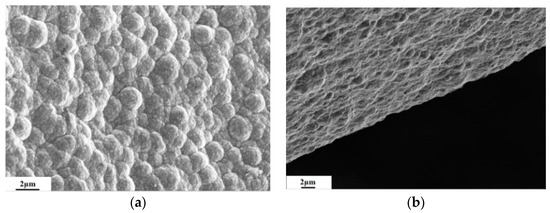
Figure 2.
Morphology of nanocrystalline diamond (NCD) coated tool. (a) Tool surface; (b) cutting edge.
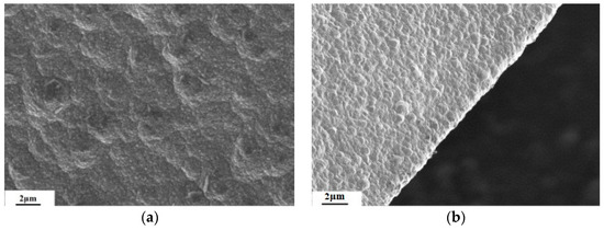
Figure 3.
Morphology of MCD/NCD coated tool. (a) Tool surface; (b) cutting edge.
The cross-sectional morphologies display columnar growth patterns for MCD coatings as shown in Figure 4a. The NCD coatings have the continuous structure of the nano-scale particles in Figure 4b. There is an obvious transition line between MCD and NCD coatings in Figure 4c. The thickness of diamond coatings can be evaluated from cross-sectional morphologies. The average thickness is about 6 μm for MCD, 6.1 μm for NCD, and 5.9 μm for MCD/NCD coatings, respectively. Figure 5 shows the Raman spectrum of all the diamond coatings. A distinct sharp peak around 1335 cm−1 is visible for MCD coating. The peak deviates from the value of natural diamond (1332 cm−1), indicating the residual stress in the diamond coatings. Accordingly, the Raman spectrum of NCD coating shows a broadened peak at 1325 cm−1 and the MCD/NCD coating shows a broadened peak at 1329 cm−1, which indicates the sp3 Raman peak [14]. The broad bands at 1580 cm−1 and 1560 cm−1 are observed in NCD and MCD/NCD coatings, corresponding to the G-band that is associated to sp2 bonds of C atoms in the grain boundaries [15,16,17].
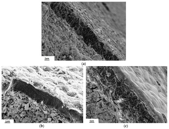
Figure 4.
Cross-sectional morphology of diamond coated tools. (a) MCD; (b) NCD; (c) MCD/NCD.
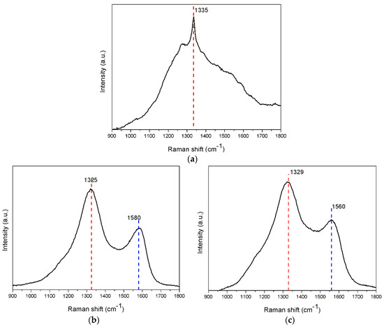
Figure 5.
Raman spectrum of diamond coatings. (a) MCD; (b) NCD; (c) MCD/NCD.
3.2. Drilling Force Characterization
The variation curves of thrust force in drilling CFRP are roughly divided into four stages [7,18]. To better depict the force generation, the calculated force values are extracted from the signal in the steady stage during drilling tests. The drilling thrust force as a function of hole number is shown in Figure 6 and Figure 7. The results show that the drill force increased with the hole number for all the tools, due to the tool wear. In Figure 6, at the initial stage of drilling tests, the values are 25 N for MCD, 18 N for NCD, and 16 N for MCD/NCD coated drills, respectively. The MCD coated drill encountered more severe friction than that of NCD and MCD/NCD coated tools, because the surfaces of NCD coatings are smoother than MCD. The forces increase with more holes drilled for all the tools due to tool wear. As to Figure 7, with the given drilling parameter n = 6000 rpm, the force values are lower than that of the MCD and NCD coated tools with a parameter of n = 4000 rpm. It suggests that the higher spindle speed brings lower force for the fresh drill. In contrast, at the end of drilling tests, with lower spindle speed and feed rate, the average force is lower attributed to the increasing feed rate leading to an increase in uncut chip thickness for the worn tool. It is obvious that the MCD/NCD coated tools exhibit the lowest force value during the drilling tests, suggesting that the dual-layer composite diamond coated tools display the most excellent performance in drilling tests. For the MCD/NCD coated tool, the force value is the lowest among all the drilling conditions. Exceptionally, the force values present similar results at the 21th hole under condition II. That may be caused by the worn surface of MCD film which becomes smooth before film delamination. It can be observed that, under the given drilling parameters n = 4000 rpm and f = 0.004 mm/r, the MCD/NCD coated tools exhibit the most excellent performance.
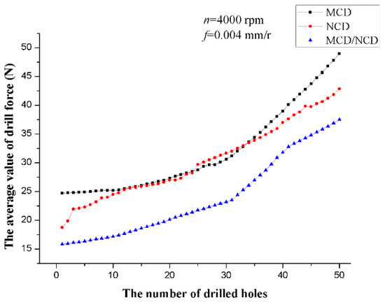
Figure 6.
Force value versus the number of drilled holes under condition I.
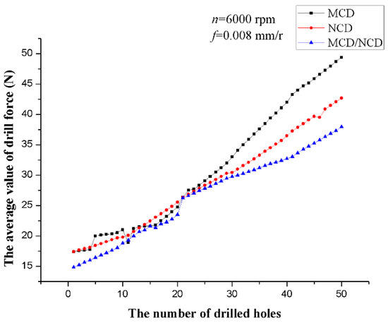
Figure 7.
Force value versus the number of drilled holes under condition II.
3.3. Tool Wear and Hole Quality
Figure 8, Figure 9 and Figure 10 show the worn cutting edges of the three type diamond coated tools at the end of the drilling tests. It suggests that all the diamond coated tools encounter abrasive wear. The worn surface area is becoming smaller from MCD to NCD/MCD surfaces. In Figure 8, the WC-Co substrates are obvious because of the film delamination. It is noted that the delamination area of MCD coated tools with condition I is smaller than that of condition II, due to the intense impact between tool and workpiece in higher speed spindle on the rough surface of MCD. As to NCD coated tools shown in Figure 9, the delamination is more severe under condition I than under condition II, which suggests the opposite phenomenon in contrast to MCD coated tools. This is attributed to smoother surfaces enduring less friction under high spindle speed. The MCD/NCD coated tools present a similar situation to NCD coated tools, but with a smaller worn area and less film delamination in Figure 10, suggesting the best performance during the CFRP drilling test. In the MCD structure, the film cracks tend to propagate through the columnar particles, leading to a decrease in toughness and adhesion. As to NCD coating, the continuous structure would relieve the crack propagation, but the hardness of NCD is lower than that of MCD. The advantages are integrated in the composite MCD/NCD structure, which leads to the high hardness and prevents crack propagation.
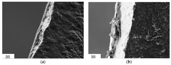
Figure 8.
Worn morphology of cutting edge for MCD coated tools. (a) n = 4000 rpm, f = 0.004 mm/r; (b) n = 6000 rpm, f = 0.008 mm/r.
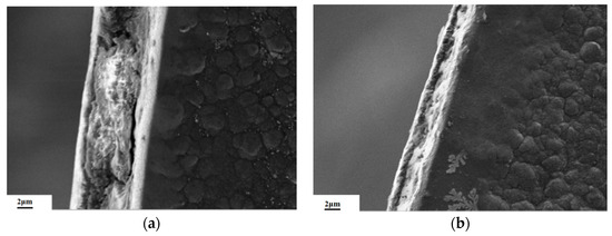
Figure 9.
Worn morphology of cutting edge for NCD coated tools. (a) n = 4000 rpm, f = 0.004 mm/r; (b) n = 6000 rpm, f = 0.008 mm/r.
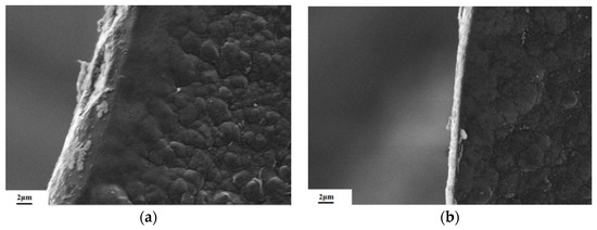
Figure 10.
Worn morphology of cutting edge for MCD/NCD coated tools. (a) n = 4000 rpm, f = 0.004 mm/r; (b) n = 6000 rpm, f = 0.008 mm/r.
Hole quality in CFRP drilling consists of output parameters including surface integrity, hole diameter, delamination, and exit burrs of drilled holes. Delamination is classified as exit hole damage which is very critical in structural durability of the composite structures. In this study, hole quality of machined CFRP specimens is evaluated with delamination damage. The delamination factor (Fd) adopted in this study is a factor defined as the ratio of the maximum diameter (Dmax) of the delamination area to the hole nominal diameter (Dnom), as illustrated in Fd = Dmax/Dnom. The morphologies of the 50th hole exit under n = 4000 rpm are shown in Figure 11. The values of Fd for the holes drilled by MCD, NCD, and MCD/NCD coated tools are 1.14, 1.09 and 1.03. It indicates that the composite coating coated tool could achieve high quality.

Figure 11.
Morphologies of hole exit. (a) MCD (b) NCD (c) MCD/NCD.
4. Conclusions
Three types of structure, namely MCD, NCD, and MCD/NCD coatings were deposited on WC-Co tools. The diamond films were characterized by SEM and Raman spectra, and the MCD particles showed a pyramidal shape, while the NCD and MCD/NCD coatings display a cauliflower-like morphology. The Raman spectra of NCD and MCD/NCD coatings suggest nano diamond features. The CFRP drilling experiments with MCD, NCD, and MCD/NCD coated tools show that the average force of MCD/NCD coated tools is lower than that of other diamond coated tools. Meanwhile, the MCD/NCD coated tools display excellent cutting performance in resistance to wear and adhesive strength. The results confirm the preferable properties of MCD/NCD coatings deposited on tools for CFRP machining. In the MCD/NCD depositing process, the MCD surfaces are filled with nano particles, which could compensate for the defects by producing a smoother surface. During the drilling tests, the composite coating structure could prevent crack propagation caused by continuous nano particles while having the high hardness of MCD.
Author Contributions
J.Z. (Jianguo Zhang) and Y.Y. conceived and designed the experiments; J.Z. (Jinjiang Zhang) performed the experiments; J.Z. (Jianguo Zhang) and Y.Y. analyzed the data; J.Z. (Jianguo Zhang) and Y.Y. wrote the paper.
Funding
This research was funded by [Natural Science Foundation of Shanghai] grant number [18ZR1401100], [the Fundamental Research Funds for the Central Universities] and [Shanghai Key Lab of Advanced Manufacturing Environment] grant number [KT20150901].
Conflicts of Interest
The authors declare no conflict of interest.
References
- Hintze, W.; Clausen, R.; Schütte, C.; Kroll, K. Evaluation of the total cutting force in drilling of CFRP: A novel experimental method for the analysis of the cutting mechanism. Prod. Eng. 2018, 12, 431–440. [Google Scholar] [CrossRef]
- Iliescu, D.; Gehin, D.; Gutierrez, M.E.; Girot, F. Modeling and tool wear in drilling of CFRP. Int. J. Mach. Tool Manuf. 2010, 50, 204–213. [Google Scholar] [CrossRef]
- Ramirez, C.; Poulachon, G.; Rossi, F.; M’Saoubi, R. Tool wear monitoring and hole surface quality during CFRP drilling. Procedia CIRP 2014, 13, 163–168. [Google Scholar] [CrossRef]
- Henerichs, M.; Voß, R.; Harsch, D.; Kuster, F.; Wegener, K. Tool life time extension with nano-crystalline diamond coatings for drilling carbon-fibre reinforced plastics (CFRP). Procedia CIRP 2014, 24, 125–129. [Google Scholar] [CrossRef]
- Mkaddem, A.; Soussia, A.B.; Mansori, M.E. Wear resistance of CVD and PVD multilayer coatings when dry cutting fiber reinforced polymers (FRP). Wear 2013, 302, 946–954. [Google Scholar] [CrossRef]
- Wang, X.; Kwon, P.Y.; Sturtevant, C.; Kim, D.; Lantrip, J. Tool wear of coated drills in drilling CFRP. J. Manuf. Process. 2013, 15, 127–135. [Google Scholar] [CrossRef]
- Yiğit, K.; Burak, D.; Onur, B. Drilling thick fabric woven CFRP laminates with double point angle drills. J. Mater. Process. Technol. 2012, 212, 2117–2127. [Google Scholar] [CrossRef]
- Ma, Y.P.; Sun, F.H.; Xue, H.G.; Zhang, Z.M.; Chen, M. Deposition and characterization of nanocrystalline diamond films on co-cemented tungsten carbide inserts. Diam. Relat. Mater. 2007, 16, 481–485. [Google Scholar] [CrossRef]
- Salgueiredo, E.; Amaral, M. Mechanical performance upgrading of CVD diamond using the multilayer strategy. Surf. Coat. Technol. 2013, 236, 380–387. [Google Scholar] [CrossRef]
- Wang, X.; Shen, X.; Yang, G.; Sun, F. Evaluation of boron-doped-microcrystalline/nanocrystalline diamond composite coatings in drilling of CFRP. Surf. Coat. Technol. 2017, 330, 149–162. [Google Scholar] [CrossRef]
- Shabani, M.; Sacramento, J.; Oliveira, F.; Rui, S. Multilayer CVD diamond coatings in the machining of an al6061-15 vol % Al2O3 composite. Coatings 2017, 7, 165. [Google Scholar] [CrossRef]
- Kuo, C.; Wang, C.; Ko, S. Wear behaviour of CVD diamond-coated tools in the drilling of woven CFRP composites. Wear 2018, 398–399, 1–12. [Google Scholar] [CrossRef]
- Zhang, J.; Cui, Y.; Shen, B.; Sun, F. Effect of silicon doping in CVD diamond films from microcrystalline to nanocrystalline on WC-Co substrates. Surf. Rev. Lett. 2013, 20, 1350055-1. [Google Scholar] [CrossRef]
- Thowladda, W.; Khlayboonme, S.T. Plasma impedance tuning effect on nanostructure of diamond films. Appl. Mech. Mater. 2013, 394, 32–37. [Google Scholar] [CrossRef]
- Yang, T.S.; Lai, J.Y.; Cheng, C.L.; Wong, M.S. Growth of faceted, ballas-like and nanocrystalline diamond films deposited in CH4/H2/Ar MPCVD. Diam. Relat. Mater. 2001, 10, 2161–2166. [Google Scholar] [CrossRef]
- Montes-Gutiérrez, J.A.; Alcantar-Peña, J.J.; Obaldia, E.; Zúñiga-Rivera, N.J.; Chernov, V.; Meléndrez-Amavizca, R.; Barboza-Flores, M.; Garcia-Gutierrez, R.; Auciello, O. Afterglow, thermoluminescence and optically stimulated luminescence characterization of micro-, nano- and ultrananocrystalline diamond films grown on silicon by HFCVD. Diam. Relat. Mater. 2018, 85, 117–124. [Google Scholar] [CrossRef]
- Lee, Y.C.; Pradhan, D.; Lin, S.J.; Chia, C.T.; Cheng, H.F.; Lin, I.N. Effect of surface treatment on the electron field emission property of nano-diamond films. Diam. Relat. Mater. 2005, 14, 2055–2058. [Google Scholar] [CrossRef]
- Xu, J.; An, Q.; Chen, M. A comparative evaluation of polycrystalline diamond drills in drilling high-strength T800S/250F CFRP. Compos. Struct. 2014, 117, 71–82. [Google Scholar] [CrossRef]
© 2018 by the authors. Licensee MDPI, Basel, Switzerland. This article is an open access article distributed under the terms and conditions of the Creative Commons Attribution (CC BY) license (http://creativecommons.org/licenses/by/4.0/).