Article

A Novel Way to Enhance the Spark Plasma-Assisted Ignition for an Aero-Engine Under Low Pressure

1
Science and Technology on Plasma Dynamics Laboratory, Air Force Engineering University, Xi’an 710038, China
2
Institute of Aero-engine, School of Mechanical Engineering, Xi’an Jiaotong University, Xi’an 710049, China
*
Authors to whom correspondence should be addressed.
Appl. Sci. 2018, 8(9), 1533; https://doi.org/10.3390/app8091533
Submission received: 9 August 2018 / Revised: 20 August 2018 / Accepted: 20 August 2018 / Published: 1 September 2018

Abstract

:
Finding a new ignition strategy for ignition enhancement in a lean-burn combustor has always been the biggest challenge for high-altitude, long-endurance unmanned aerial vehicles (UAVs). It is of great importance for the development of high-altitude, long-endurance aircraft to improve the secondary ignition ability of the aero-engine at high altitude where the ignition capability of the aero-engine igniter rapidly declines. An innovative ignition mode is therefore urgently needed. A novel plasma-assisted ignition method based on a multichannel discharge jet-enhanced spark (MDJS) was proposed in this study. Compared to the conventional spark igniter (SI), the arc discharge energy of the MDJS was increased by 13.6% at 0.12 bar and by 14.7% at 0.26 bar. Furthermore, the spark plasma penetration depth of the MDJS was increased by 49% and 103% at 0.12 bar and 0.26 bar, respectively. The CH* radicals showed that the MDJS obtained a larger initial spark kernel and reached a higher spark plasma penetration depth, which helped accelerate the burning velocity. Ignition tests in a model swirl combustor showed that the lean ignition limit was extended 24% from 0.034 to 0.026 at 25 m/s with 20 °C kerosene and 17% from 0.075 to 0.062 at 12 m/s with −30 °C kerosene maximally. The MDJS was a unique plasma-assisted ignition method, activated by the custom ignition power supply instead of a special power supply with an extra gas source. The objective of this study was to provide a novel multichannel discharge jet-enhanced spark ignition strategy which would help to increase the arc discharge energy, the spark plasma penetration depth and the activated area without changing the power supply system and to improve the safety and performance of aero-engines.

1. Introduction

It is crucially important for the safety and development of aero-engines to improve the secondary ignition ability because of the relatively low pressure, low temperature and high velocity of inlet air [1,2,3]. Once an aircraft has reached a flight height where the engine stops and the requirements for successful relight cannot be met, it is forced to move to a lower flight height to achieve secondary ignition. However, the aircraft’s lower flight height will greatly increase the probability of it being detected and attacked due to its weak self-protection capability. Therefore, improving the secondary ignition ability of the igniter plays a vital role in the safety and performance of aircraft. Low pressure and low temperature may cause many problems, for example, a poor fuel vaporization and a slow chemical reaction, a reduced appropriate ignition area, an increased minimum ignition energy, a reduced ignition energy, and a subdued spark penetration capability, which result in the lack of a secondary ignition ability in an aero-engine ignition system [4]. Not only the ignition energy but also the spatial evolution characteristic of the initial spark kernel limit the improvement of the secondary ignition ability [5]. A sufficient spark penetration depth of the initial spark kernel can not only prolong the service life of the igniter but also help increase the probability of contact with the flammable hydrocarbon mixture of stoichiometric ratio, which contributes to the secondary ignition ability of the igniter. Based on spark discharge, researchers have proposed a variety of multichannel spark ignition methods [6,7,8], which can increase ignition energy but result in the increased complexity and reduced reliability of the ignition system. Compared with the surface spark discharge ignition, the plasma jet ignition has a significant advantage in improving the spark penetration depth of the initial spark kernel [9,10,11]. However, the plasma jet igniter is based on the external gas source, which increases the complexity of the whole ignition system and becomes an obstacle to its application. Researchers have also proposed other types of ignition methods, such as nanosecond pulse plasma-assisted ignition [12], radio frequency plasma ignition [13], microwave plasma-assisted ignition [14,15], laser plasma-assisted ignition [16,17], DC plasma ignition [18], and so on. However, there is still much work to be done due to the severe electromagnetic interference of the nanosecond pulse discharge, the complex power supply, and the fairly large size and weight of radio-frequency (RF) discharge and microwave discharge. At this time, a more practical ignition system with an excellent secondary ignition performance for relight of aero-engines at high altitude is urgently needed [19]. Following the development of plasma synthetic jet actuators, the gas inside the cavity is rapidly heated and pressurized by the strong pulsed spark between the internal electrode couple. The gas is then expelled through the orifice at a very high velocity (up to 30–120 m/s in 100 μs after the discharge) due to the difference of the pressure between the internal cavity and the ambient pressure [20,21,22]. Consequently, in order to increase the penetration depth of the spark/arc, this is a highly feasible way to take advantage of the high-temperature and high-velocity jet to push the spark/arc, similar to what the plasma torch igniter does [23].
Therefore, in this study, a novel ignition method based on a multichannel discharge jet-enhanced spark (MDJS) was proposed. The MDJS was still activated by the same ignition power supply as the conventional spark igniter, so no extra weight was added to the unmanned aerial vehicle (UAV). In addition, there was little electromagnetic interference by employing the conventional ignition power supply rather than the nanosecond pulse discharge power supply of high frequency. The larger ignition kernel and the higher spark penetration depth driven by the MDJS were confirmed at 0.12 bar and 0.26 bar (0.12 bar represents the air pressure at an altitude of approximately 15 km and 0.26 bar represents the air pressure at an altitude of approximately 10 km), and the SI and MDJS ignition experiments were conducted with 20 °C and −30 °C kerosene. The MDJS not only could take advantage of the jet, but it also could run independently without a gas source. The objective of this study was to provide a prospective multichannel discharge technique without changing power supply system and to improve the safety and performance of aero-engines.

2. Experimental Setup and Procedure

Figure 1a shows an anode and a cathode, surface-mounted with a 2 mm wide gap, that is assembled in a conventional spark igniter (SI). As shown in Figure 1b, a multichannel discharge jet-enhanced spark (MDJS) is mainly composed of a cavity, an orifice, and two pairs of electrode couples, where one electrode couple with a 2 mm wide gap is assembled in the same conventional way, and the other electrode couple with a 2 mm wide gap is placed inside a horizontally arranged and cylindrical cavity that is 4 mm in length and 1 mm in diameter. The volume of the confined cavity is approximately 2.28 mm3, and a 1 mm orifice with a depth of 1 mm is punched in the middle of the surface-mounted electrode couple. The breakdown of the internal electrode couple (EC1) instantly releases energy to heat up the gas inside the cavity and thus forms a jet stream which pushes the arc between the external electrode couple (EC2) forward. Therefore, a novel method based on a multichannel discharge jet-enhanced spark was discovered.
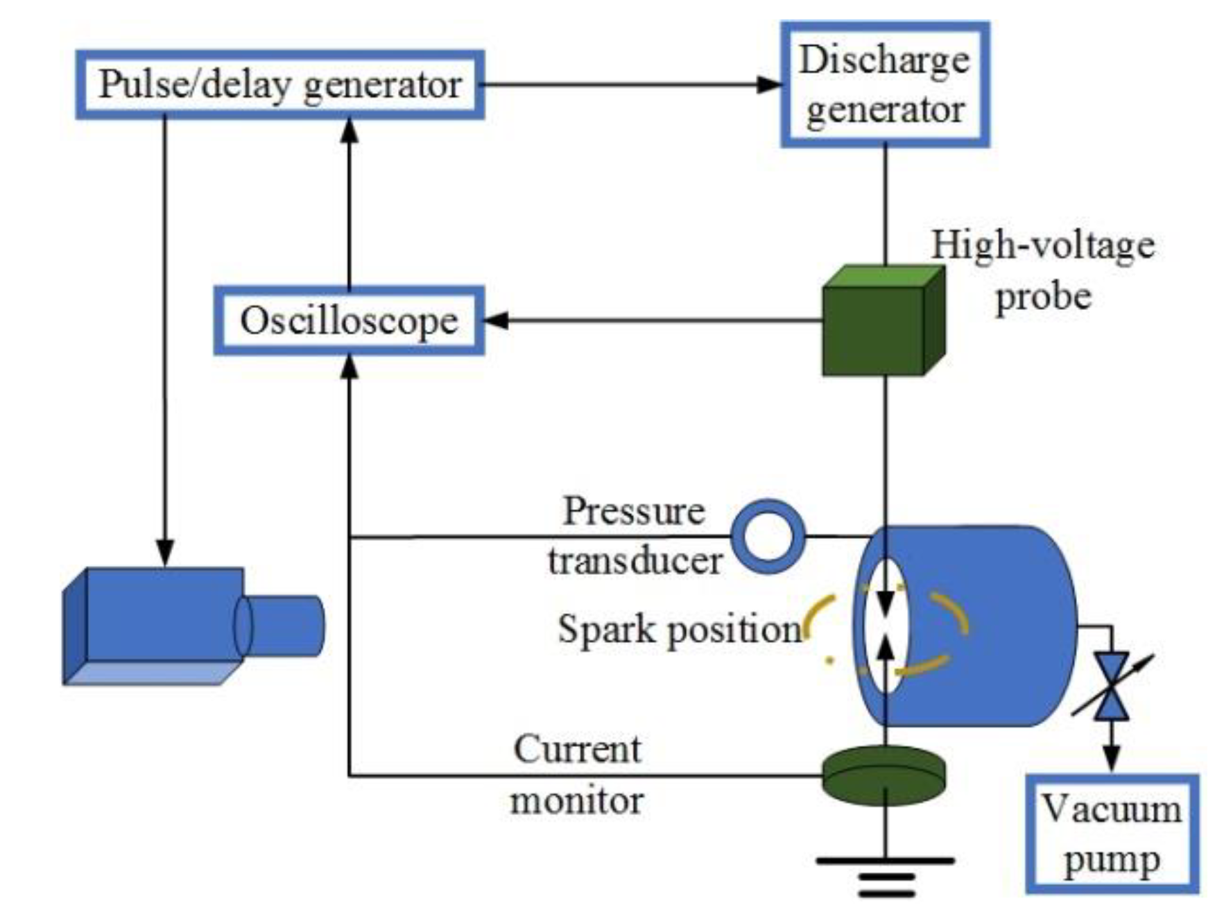
Figure 2 depicts the experimental apparatus. A cylindrical pressure vessel having an inner diameter of 30 cm and a circular observation window was used to measure the discharge characteristic and capture the spark luminosity imaging at low pressure (0.12–0.26 bar). The in-vessel pressure was measured with a pressure transducer (MKS BARATRON 112A). To measure voltage and current during the discharge, a 75-MHz high-voltage probe (Tektronix P6015A) and a 120-MHz current probe (Pearson 6600) were employed. A 1-GHz oscilloscope (Tektronix DPO4014) was utilized to record the two signals, and the output trigger command to the high-speed CCD camera (Phantom-v2512), with which the development of the spark plasma volume, the spark penetration depth and the activated area at sub-atmospheric pressures (0.12–0.26 bar) were captured, was obtained through a pulse generator (DG535). When characterizing spark plasma volume and activated area development, the Phantom-v2512 imaging was performed at a shutter speed of 200,000 fps with a resolution of 256 × 256 pixels and an exposure time of 1 μ s . A high-speed camera equipped with a bandpass filter (centered at 430 nm, with a 10 nm FWHM (full width half maximum) was used to record the CH* chemiluminescene from the combustor side view.
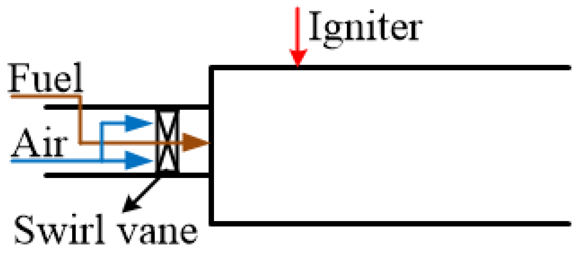
As shown in Figure 3, the ignition test was conducted at 0.26 bar in a model swirl combustor, and a quartz window with a height and length of 220 mm and 68 mm, respectively, was mounted on the side wall. In addition, an atomizing nozzle (Danfus 0.85) with a spray angle of 30 degrees was employed.

3. Results and Discussion

3.1. Discharge Characteristics of the SI and the MDJS

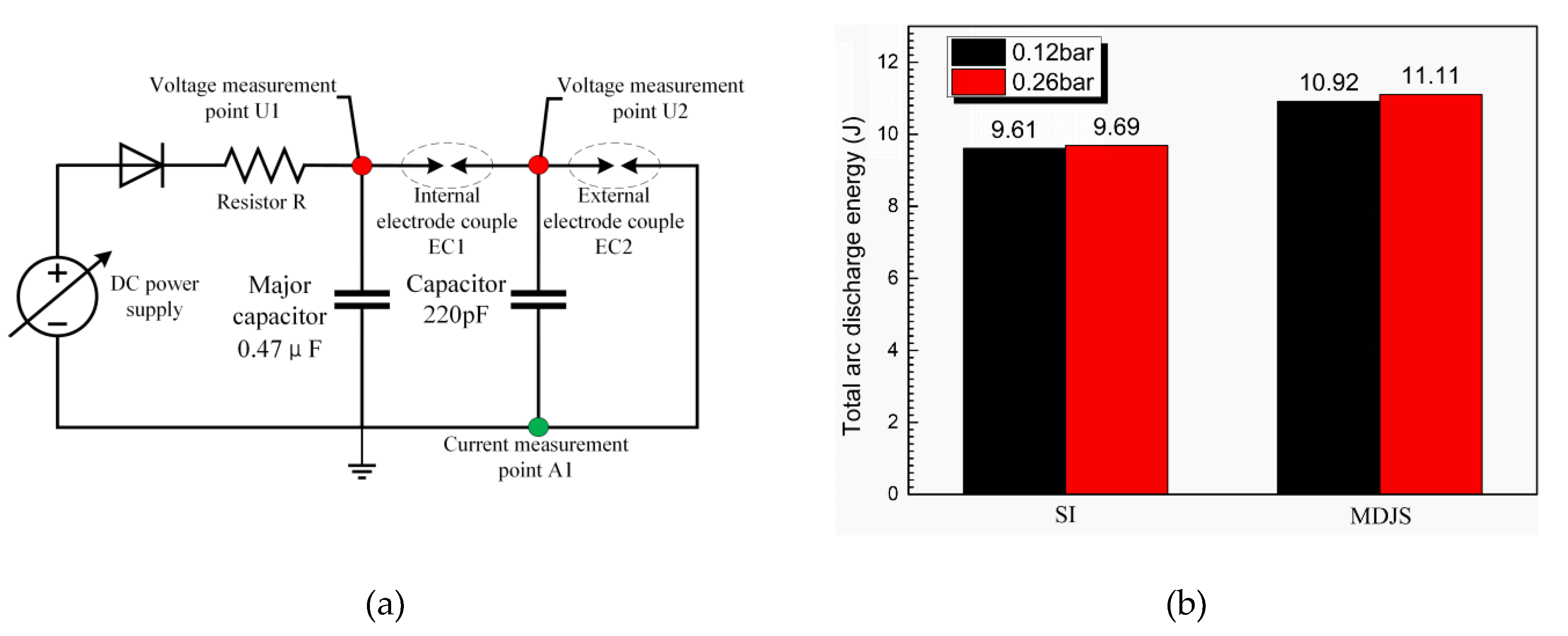
A double-channel discharge jet-enhanced spark was obtained due to the voltage relay mechanism shown in Figure 4a. The stored energy of the power supply is 12 J and the peak-to-peak voltage is approximately 8 kV. The high voltage probe was connected to the point close to the igniter so that there was little energy loss in the cables during the discharge process. The total arc discharge energy of the SI and the MDJS was quantitatively measured, and the results are shown in Figure 4b. It was found that the total arc discharge energy of the MDJS increased by approximately 14% in comparison to the conventional SI.

3.2. Spark Characteristics of the SI and the MDJS

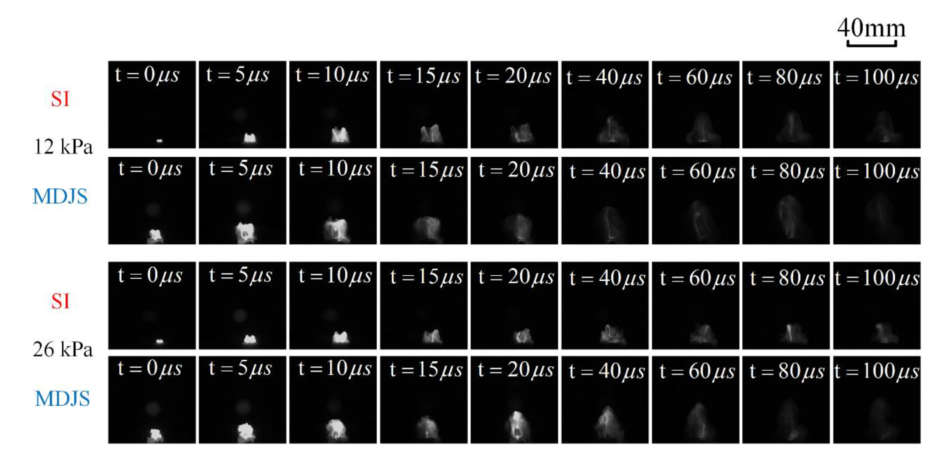
Discharge images (including spark volume, spark penetration depth and activated area development) of the SI and the MDJS from a side view at different pressures ranging from 0.12 bar to 0.26 bar are shown in Figure 5. At first, the conventional SI discharge in Figure 5 shows a fine filament, whereas the MDJS shows a much brighter arc discharge after an ionization path among EC1 and EC2 is created.
As is shown in Figure 6, the MDJS discharge is visualized as a jet-enhanced spark: the external spark was pushed forward by the high-temperature jet which was rapidly heated and pressurized by the strong pulsed spark between the internal electrode couple EC1, which resembles a cambered arc. However, the conventional spark igniter generated a much lower spark plasma penetration depth and a relatively smaller spark plasma activated area. Figure 6 a,b shows that the spark plasma penetration depth of the SI is 10.9 mm, whereas that of the MDJS is approximately 19.1 mm. A higher spark plasma penetration depth of the initial spark kernel generated by the MDJS can not only prolong the service life of the igniter but also help increase the probability of contact with the flammable hydrocarbon mixture of stoichiometric ratio, which contributes to improving the secondary ignition ability of the igniter.
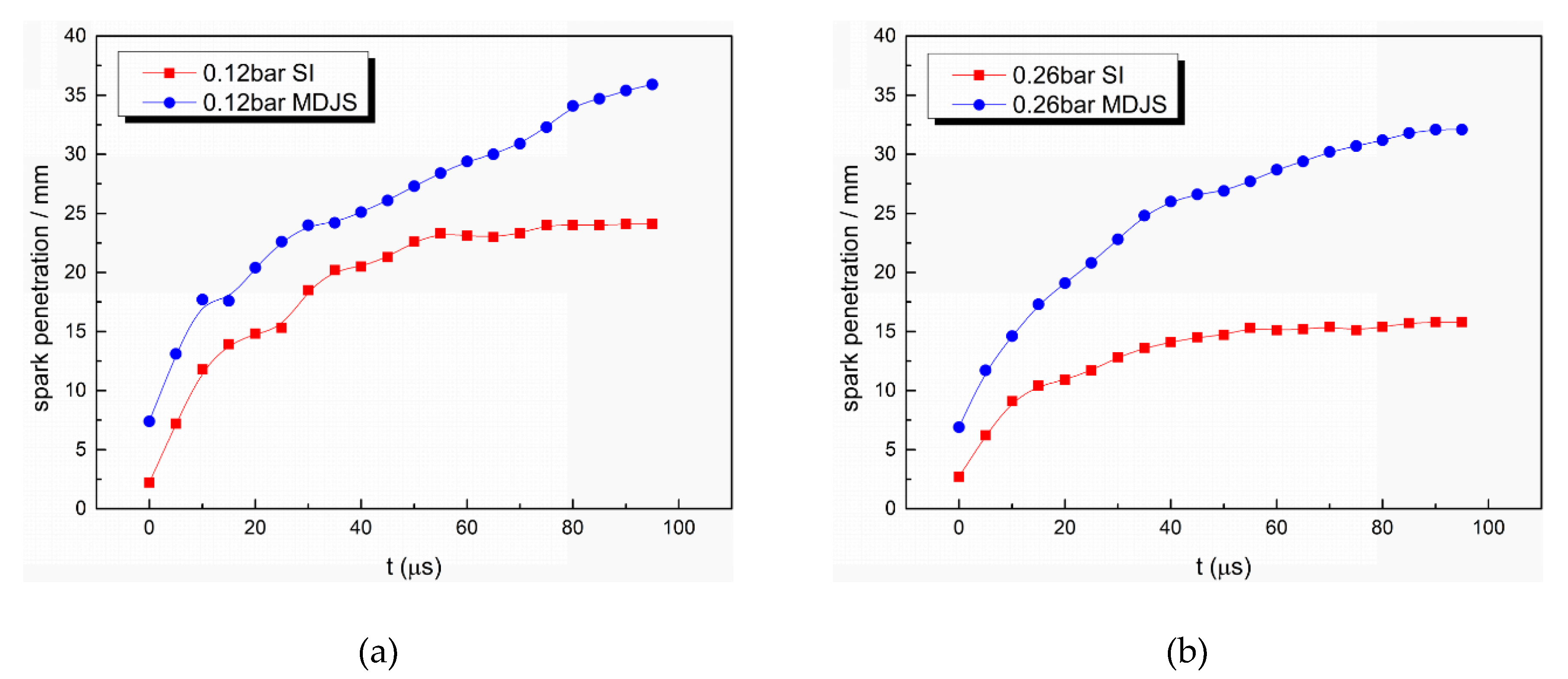
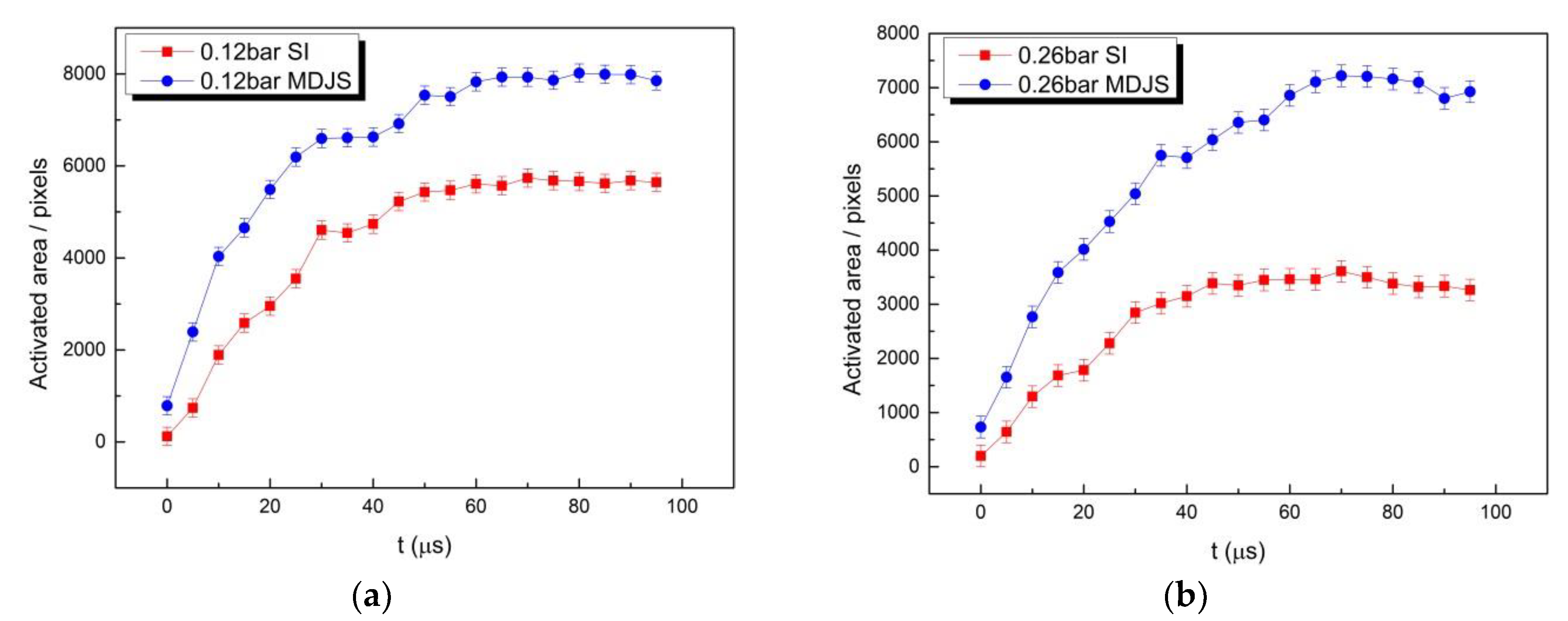
In addition, Figure 7 and Figure 8 show that a higher spark plasma penetration depth and a larger activated area at a faster rate, particularly before 40 μ s , were observed using the MDJS. This means the MDJS generates a much larger plasma volume and a fast growing spark kernel in comparison to the conventional SI. At the beginning of the discharge, the MDJS generated a spark plasma penetration depth which was approximately 3 times higher than that of the SI, and an activated area which was approximately 2.5 times larger than that of the SI. Then, the spark plasma penetration depth of the MDJS increased at a faster rate than the SI over time at 0.26 bar, and the activated area showed a similar trend. When the pressure was lowered to 0.12 bar, the MDJS still showed a deeper spark penetration depth and a larger activated area, which was not as obvious as at the higher-pressure state (0.26 bar). That occurred because the air was so thin that the high-temperature gas inside the cavity could not be expelled outside the orifice as fast as it could under the higher-pressure state (0.26 bar). At 100 μ s , the spark plasma penetration depth of the MDJS was increased by 49% and 103% at 0.12 bar and 0.26 bar, respectively. In addition, the activated area generated by the MDJS was increased by 39% and 112% at 0.12 bar and 0.26 bar, respectively.
Because the MDJS could not only generate a much higher arc discharge energy and a higher spark penetration depth but also create a much larger plasma volume as well as an activated area in comparison to the SI, it has the potential to achieve a successful ignition more easily in a fuel-lean state in an aero-engine combustor.

3.3. Effect of the MDJS on the Ignition Process and the Ignition Limit Extension

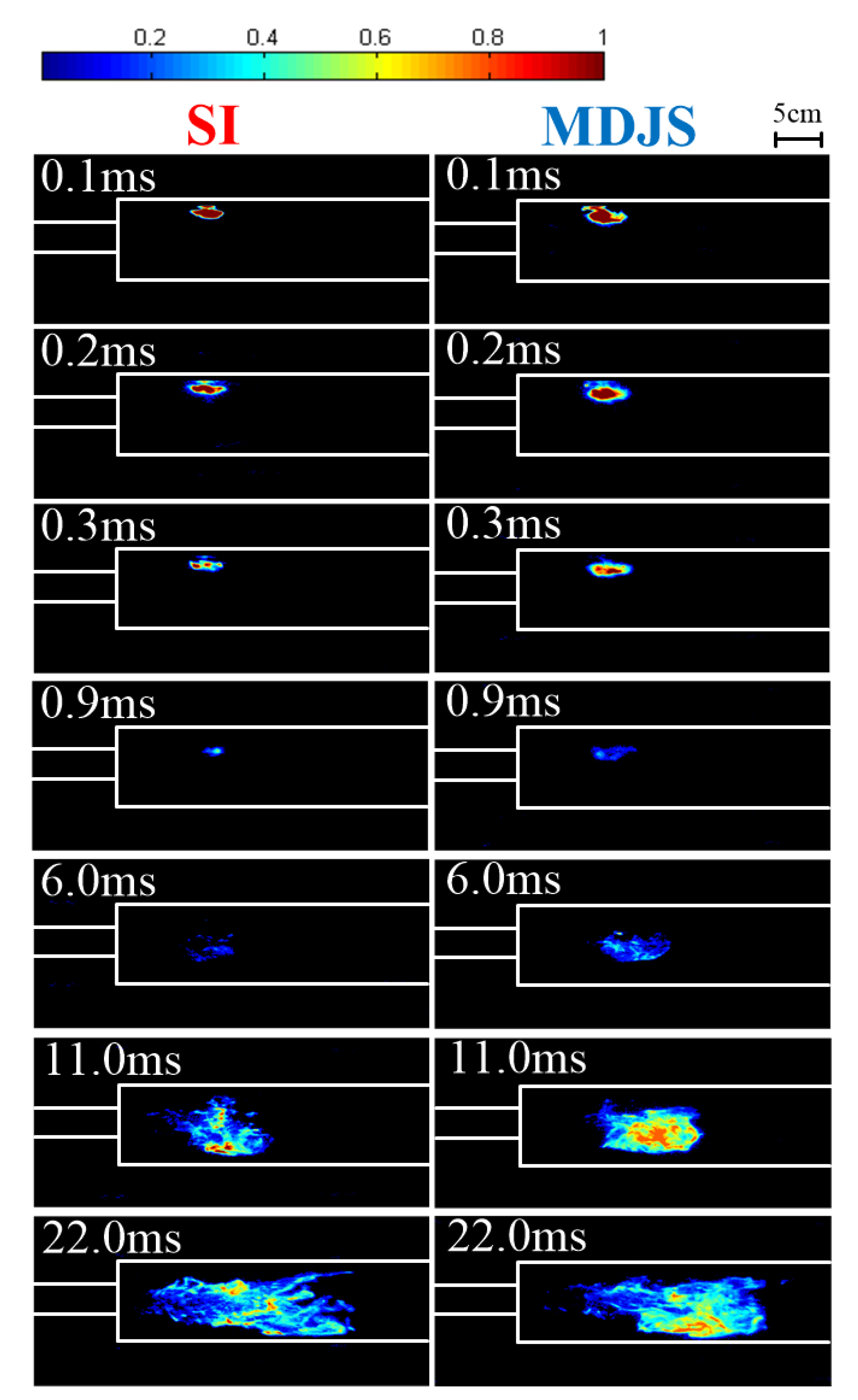
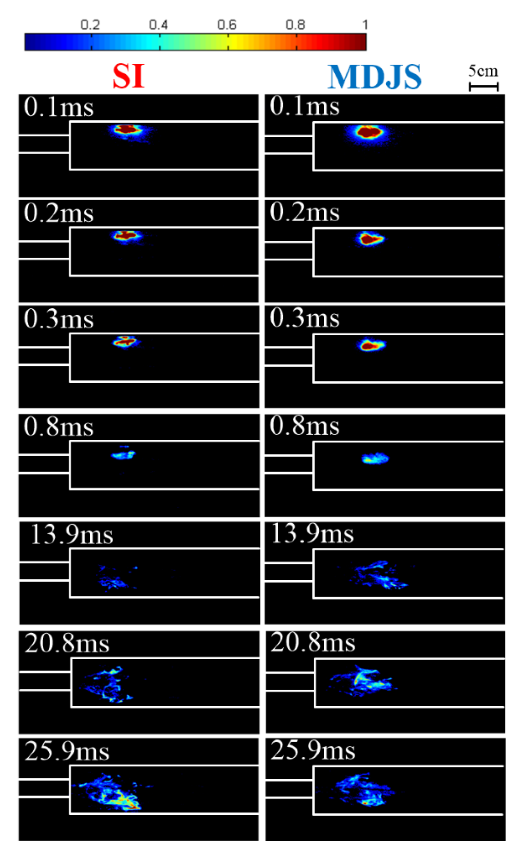
In order to investigate the lean ignition limits of the SI and the MDJS and to minimize the effects of random elements that may be involved, data from five tests were obtained to plot one curve. The global equivalence was gradually reduced by decreasing the fuel flow rate, and this process was repeated at different air flow rates (AFRs). Figure 9 shows a representative distribution as well as the intensity of CH* radicals with the SI and the MDJS at 0.26 bar when φ = 0.081. A false-color enhancement technology was used when comparing the SI with the MDJS. As is shown in Figure 9, the flame kernel formed at the top wall is bright at t = 0.1   ms and it begins growing in strength and propagating inside the combustor. By 22 ms, it has filled the combustor which indicates that the combustor has settled into a quasi-stable burning state.
A larger initial spark kernel and a higher spark plasma penetration depth of the MDJS were observed. These were beneficial to the ignition performance because of the critical flame radius theory. Moreover, it was observed that when t = 6   ms and t = 11   ms , a larger initial spark kernel and a higher spark plasma penetration depth of the MDJS helped to accelerate burning velocities.
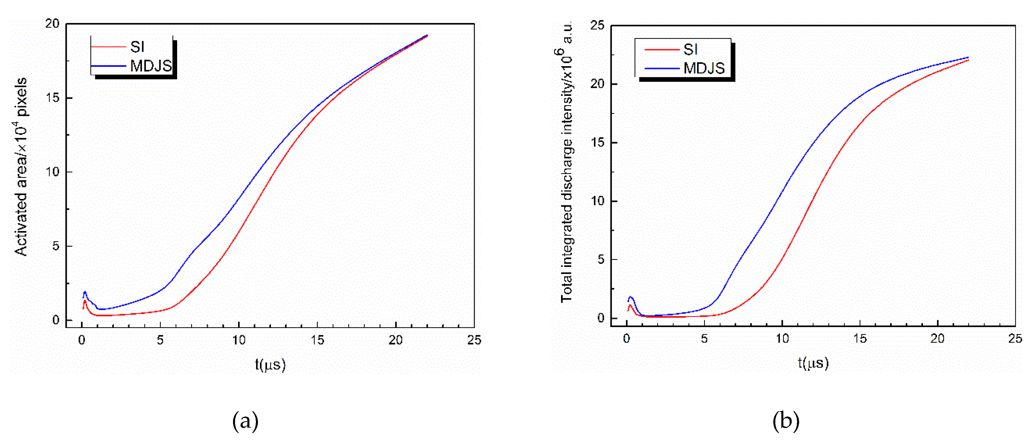
Figure 10 shows a quantitative comparison of the light intensity which indicates that the activated area of the MDJS was much larger at the beginning and grew faster than that of the SI. However, the activated area of the SI and the MDJS became the same due to the same equivalent ratio and under the same operating conditions. The total integrated discharge intensity of the MDJS was also greater than that of the SI and it showed a similar trend with the activated area.
Figure 11 shows CH* chemiluminescence images of the SI and MDJS ignition processes when φ = 0.04 at 0.26 bar. The MDJS generates a much larger initial flame kernel which grows faster in strength and shows a greater flame propagation speed than that of the SI.
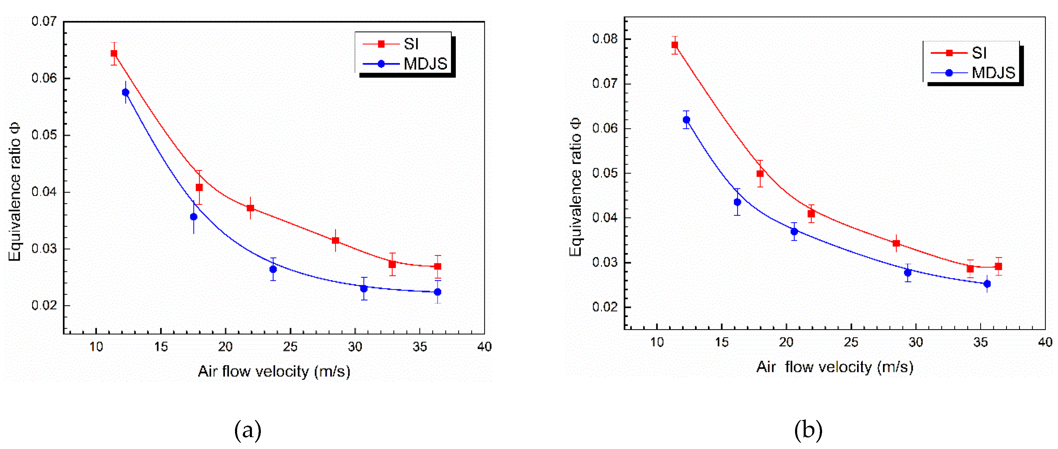
The comparison of the lean ignition limits of the SI and the MDJS with kerosene at 20 °C (local room temperature) and −30 °C is shown in Figure 12. It is readily observed that the lean ignition limit expands with the increasing air flow velocity, a result which is different from those concluded in previous work. This occurs because the fuel flow rate must be raised to keep the equivalence ratio constant while the air flow velocity increases. A much higher pressure is loaded onto the fuel atomizer to maintain a larger fuel flow rate, and that leads to a higher pressure drop ( Δ p / p ) between the ambient air flow and the fuel atomizer, a situation which contributes to atomization and evaporation. For the same air flow velocity, a noticeable extension of the lean ignition limit is observed using the MDJS with normal and low-temperature kerosene. The lean ignition limit is extended 24% from 0.034 to 0.026 at 25 m/s with 20 °C kerosene and 17% from 0.075 to 0.062 at 12 m/s with −30 °C kerosene maximally. An improvement of the MDJS is expected via thermal, kinetic, and transport parameters [24]. The MDJS performs at a higher spark plasma penetration depth, which takes more energy to heat the gas and accelerate the combustion chemical reactions. With respect to the kinetic pathway, the MDJS produces active radicals and takes them to a deeper area of the combustor where it is more likely that the spark kernel will meet the gas–oil mixture at stoichiometric ratio. For the transport effects of the MDJS, the high-velocity jet expelled through the orifice helps change the distribution of kerosene and improve mixing to some extent.
A novel multichannel discharge jet-enhanced spark (MDJS) ignition method for aero-engines was proposed. Compared to the conventional SI, the higher total arc discharge energy and the larger plasma volume driven by the MDJS significantly deepened the spark plasma penetration depth and broadened the activated area which helped induce a greater and faster-growing initial flame kernel. The MDJS and the SI were both activated by the custom ignition power supply system instead of a specific power supply with an extra gas source. Furthermore, the MDJS was the same size as the SI, which means that the MDJS can replace the conventional SI quite conveniently. The larger initial spark kernel and the higher spark penetration depth are the key facts for using a multichannel discharge jet-enhanced spark to improve ignition capability. An extension of the ignition limit in a lean-burn model swirl combustor was obtained with the MDJS under low temperature. This can largely improve high-altitude secondary ignition capability of long-endurance aircraft, which helps to promote the energy efficiency of the aero-engine combustor in the future. In brief, the MDJS, activated by the same condition power supply as the SI, could produce a stronger arc discharge energy (for its higher energy utilization) and induce a larger flame kernel which spreads at a faster rate. With the same cost, the MDJS could be a potential way of enhancing the spark plasma-assisted ignition for an aero-engine under low pressure.

4. Conclusions

A novel multichannel discharge jet-enhanced spark plasma igniter for an aero-engine combustor was proposed to significantly increase the arc discharge energy and spark plasma penetration depth to induce a greater initial spark kernel. Ignition tests for a model swirl combustor fueled by RP-3 were conducted. Discharge characteristics were conducted to investigate the advantage of the MDJS with respect to arc discharge energy. High-speed photography of the spark luminosity and CH* radicals was used to characterize the spark plasma penetration depth, the activated area and the SI and MDJS ignition processes.
(1)
The total arc discharge energy of the MDJS increased by approximately 14% in comparison to the conventional SI.
(2)
The MDJS generated a much larger spark plasma volume and a fast growing spark kernel in comparison to the conventional SI. Moreover, the MDJS with a higher spark plasma penetration depth not only helped prolong the service life of the igniter but also helped increase the probability of contact with the flammable hydrocarbon mixture at stoichiometric ratio, which contributed to the secondary ignition ability of the igniter.
(3)
The burning velocity of the flame ignited by the MDJS was faster than that ignited by the SI.
(4)
Using the multichannel discharge jet-enhanced spark, the lean ignition limit of a model swirl combustor was extended 24% from 0.034 to 0.026 at 25 m/s with 20 °C kerosene. If fueled by −30 °C kerosene, the lean ignition limit was extended 17% from 0.075 to 0.062 at 12 m/s.

Author Contributions

Experiments design, S.H.; Validation, Y.W..; Formal Analysis, Z.Z. and H.S.; Paper Writing, S.H.; Supervision, Y.L.

Funding

This research was funded by the National Natural Science Foundation of China (NSFC), under the following grant numbers (Nos. 91541120, 91641204, 51790511).

Conflicts of Interest

The authors declare no conflict of interest.

References

  1. Sun, W.; Ju, Y.J. Nonequilibrium plasma-assisted combustion: A review of recent progress. Plasma Fusion Res. 2013, 89, 208–219. [Google Scholar]
  2. Lin, B.; Wu, Y.; Zhang, Z.; Chen, Z. Multi-channel nanosecond discharge plasma ignition of premixed propane/air under normal and sub-atmospheric pressures. Combust. Flame 2017, 182, 102–113. [Google Scholar] [CrossRef]
  3. Huang, S.; Wu, Y.; Song, H.; Zhu, J.; Zhang, Z.; Song, X.; Li, Y. Experimental investigation of multichannel plasma igniter in a supersonic model combustor. Exp. Therm. Fluid Sci. 2018, 99, 315–323. [Google Scholar] [CrossRef]
  4. Ballal, D.; Lefebvre, A.H. Ignition of Liquid Fuel Sprays at Subatmospheric Pressures. Combust. Flame 1978, 31, 115–126. [Google Scholar] [CrossRef]
  5. Chen, Z.; Ju, Y. Theoretical analysis of the evolution from ignition kernel to flame ball and planar flame. Combust. Theory Model. 2007, 11, 427–453. [Google Scholar] [CrossRef]
  6. Yu, S.; Xie, K.; Tan, Q.Y.; Zheng, M.B. Ignition Improvement of Premixed Methane-Air Mixtures by Distributed Spark Discharge. In Proceedings of the JSAE/SAE 2015 International Powertrains, Fuels & Lubricants Meeting, Kyoto, Japan, 1–4 September 2015. [Google Scholar]
  7. Nakamura, N.; Baika, T.; Shibata, Y. Multipoint Spark Ignition for Clean Combustion; SAE Technical Paper 852092; SAE International: Warrendale, PA, USA, 1985. [Google Scholar] [CrossRef]
  8. Hnatiuc, B.; Hnatiuc, E.; Peller, S.; Chapelle, J. Experimental analysis of a double-spark ignition system. Czechoslov. J. Phys. 2006, 56, 851–867. [Google Scholar] [CrossRef]
  9. Kuo, S.; Bivolaru, D.; Carter, C.; Jacobsen, L.; Williams, S. Operational Characteristics of a Plasma Torch in a Supersonic Cross Flow. Available online: https://arc.aiaa.org/doi/abs/10.2514/6.2003-1190 (accessed on 1 September 2018).
  10. Li, F.; Yu, X.; Tong, Y.; Shen, Y.; Jian, C.; Chen, L.; Chang, X. Plasma-assisted ignition for a kerosene fueled scramjet at Mach 1.8. Aerosp. Sci. Technol. 2013, 28, 72–78. [Google Scholar] [CrossRef] [Green Version]
  11. Takita, K.; Abe, N.; Masuya, G.; Ju, Y. Ignition enhancement by addition of NO and NO2 from a N2/O2 plasma torch in a supersonic flow. Proc. Combust. Inst. 2007, 31, 2489–2496. [Google Scholar] [CrossRef]
  12. Starikovskaia, S.M. Plasma-assisted ignition and combustion: Nanosecond discharges and development of kinetic mechanisms. J. Phys. D Appl. Phys. 2014, 47, 353001. [Google Scholar] [CrossRef]
  13. Chintala, N.; Bao, A.; Lou, G.; Adamovich, I.V. Measurements of combustion efficiency in nonequilibrium RF plasma-ignited flows. Combust. Flame 2006, 144, 744–756. [Google Scholar] [CrossRef] [Green Version]
  14. Nishiyama, A.; Ikeda, Y. Improvement of Lean Limit and Fuel Consumption Using Microwave Plasma Ignition Technology. Available online: https://www.sae.org/publications/technical-papers/content/2012-01-1139/ (accessed on 1 September 2018).
  15. Fuh, C.A.; Wu, W.; Wang, C. Microwave plasma-assisted ignition and flameholding in premixed ethylene/air mixtures. J. Phys. D Appl. Phys. 2016, 49, 285202. [Google Scholar] [CrossRef]
  16. Morsy, M.H. Review and recent developments of laser ignition for internal combustion engines applications. Renew. Sustain. Energy Rev. 2012, 16, 4849–4875. [Google Scholar] [CrossRef]
  17. Brieschenk, S.; O’Byrne, S.; Kleine, H. Laser-induced plasma ignition studies in a model scramjet engine. Combust. Flame 2013, 160, 145–148. [Google Scholar] [CrossRef]
  18. Zhang, H.; He, L.; Chen, G.; Qi, W.; Yu, J. Experimental study on ignition characteristics of kerosene–air mixtures in V-shaped burner with DC plasma jet igniter. Aerosp. Sci. Technol. 2018, 74, 56–62. [Google Scholar] [CrossRef]
  19. Read, R.W. Experimental Investigations into High Altitude Relight of a Gas Turbine. Ph.D. Thesis, University of Cambridge, Cambridge, UK, 2008. [Google Scholar]
  20. Zong, H.; Kotsonis, M. Characterisation of plasma synthetic jet actuators in quiescent flow. J. Phys. D Appl. Phys. 2016, 49, 335202. [Google Scholar] [CrossRef] [Green Version]
  21. Zhang, Z.; Wu, Y.; Sun, Z.; Song, H.; Jia, M.; Zong, H.; Ling, Y. Experimental research on multichannel discharge circuit and multi-electrode plasma synthetic jet actuator. J. Phys. D Appl. Phys. 2017, 50, 165205. [Google Scholar] [CrossRef] [Green Version]
  22. Zong, H.; Kotsonis, M. Formation, evolution and scaling of plasma synthetic jets. J. Fluid Mech. 2018, 837, 147–181. [Google Scholar] [CrossRef]
  23. Henriques, J.; Tatarova, E.; Dias, F.M.; Ferreira, C.M. Microwave N2–Ar plasma torch. II. Experiment and comparison with theory. J. Appl. Phys. 2011, 109, 023302. [Google Scholar] [CrossRef]
  24. Ju, Y.; Sun, W. Plasma assisted combustion: Dynamics and chemistry. Prog. Energy Combust. Sci. 2015, 48, 21–83. [Google Scholar] [CrossRef]
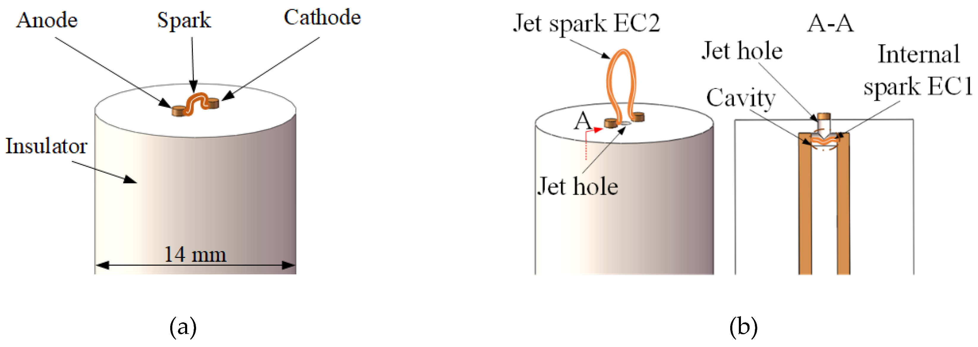
Figure 1. Structure of (a) a conventional spark igniter (SI) and (b) a multichannel discharge jet-enhanced spark (MDJS).
Applsci 08 01533 g001
Figure 2. Schematic diagram of the experimental apparatus.
Applsci 08 01533 g002
Figure 3. Schematic of the model swirl combustor.
Applsci 08 01533 g003
Figure 4. Separation of spark discharge for the MDJS: (a) electrical circuit and measurement points; and (b) total arc discharge energy of the SI and the MDJS at different pressures.
Applsci 08 01533 g004
Figure 5. Spark plasma volume and activated area development from a side view of the SI and the MDJS at different pressures.
Applsci 08 01533 g005
Figure 6. Detailed structure of (a) the conventional spark igniter (SI) and (b) the multichannel discharge jet-enhanced spark (MDJS) at 20 μ s in an ambient pressure of 0.26 bar.
Applsci 08 01533 g006
Figure 7. Spark plasma penetration depth of the SI and the MDJS at (a) 0.12 bar and (b) 0.26 bar.
Applsci 08 01533 g007
Figure 8. Activated area of SI and MDJS at (a) 0.12 bar and (b) 0.26 bar.
Applsci 08 01533 g008
Figure 9. CH* chemiluminescence images of ignition processes using the SI and the MDJS when φ = 0.081 at 0.26 bar.
Applsci 08 01533 g009
Figure 10. Activated area and total integrated discharge intensity of the SI and the MDJS when φ = 0.081 at 0.26 bar.
Applsci 08 01533 g010
Figure 11. CH* chemiluminescence images of SI and MDJS ignition processes when φ = 0.04 at 0.26 bar.
Applsci 08 01533 g011
Figure 12. Lean ignition limit using the SI and the MDJS with (a) 20 °C and (b) −30 °C kerosene.
Applsci 08 01533 g012