Comparison between Capacitive and Microstructured Optical Fiber Soil Moisture Sensors


 ,
,  , ,
, ,
Abstract
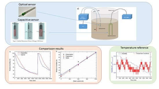
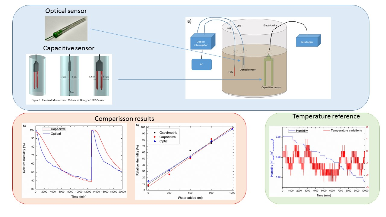
1. Introduction
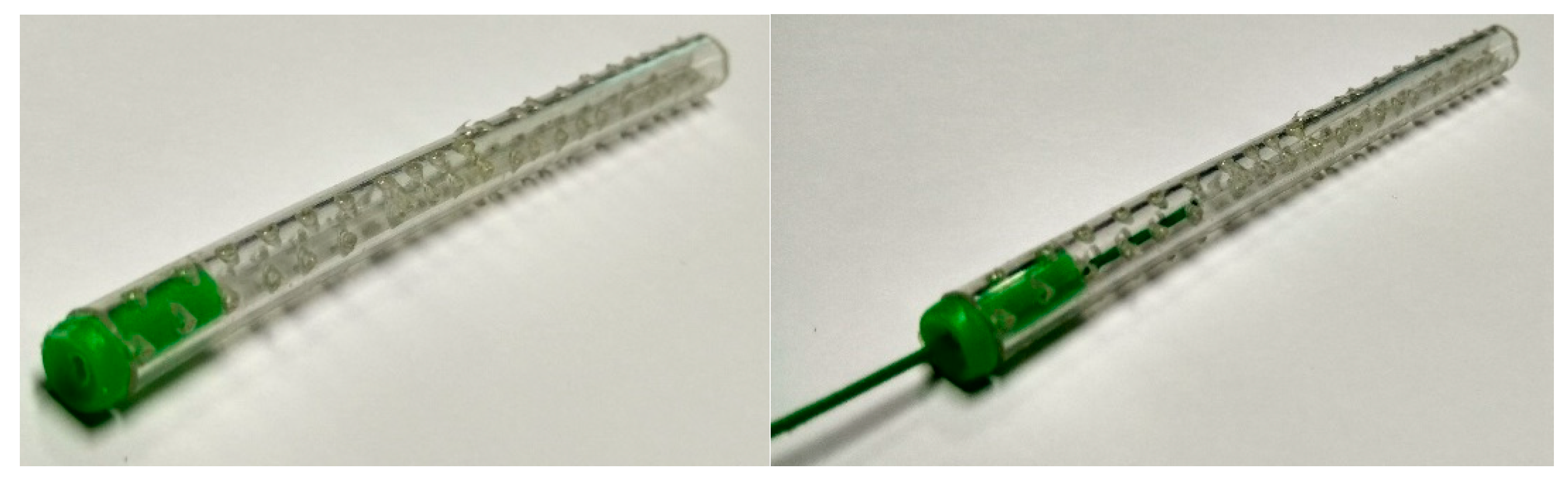
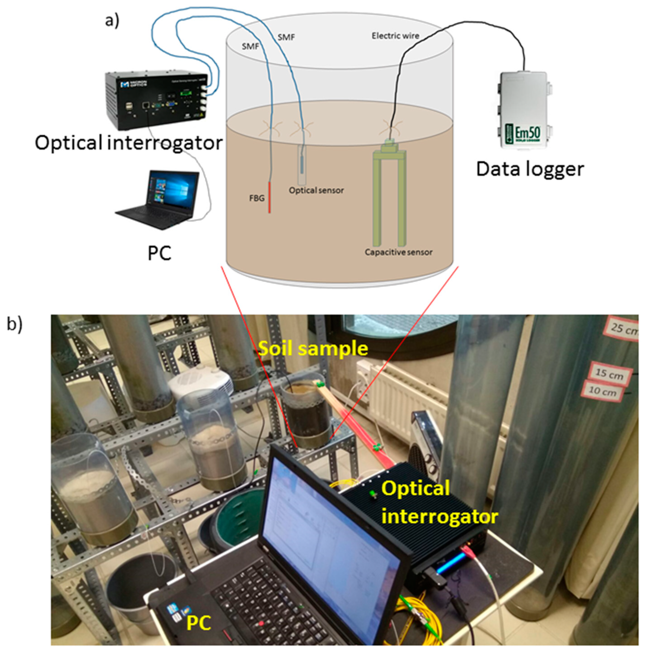
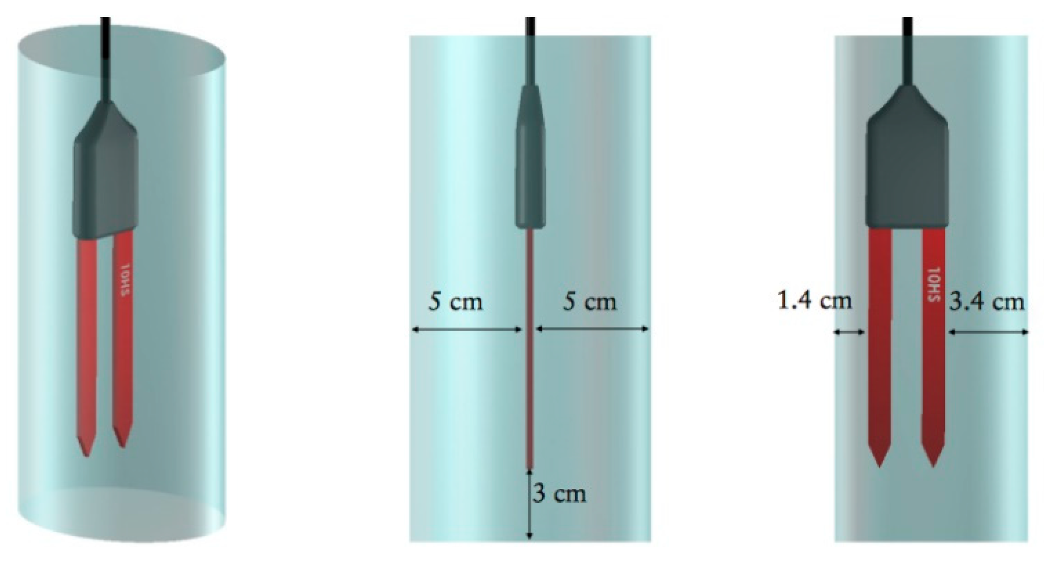
2. Materials and Methods
3. Results
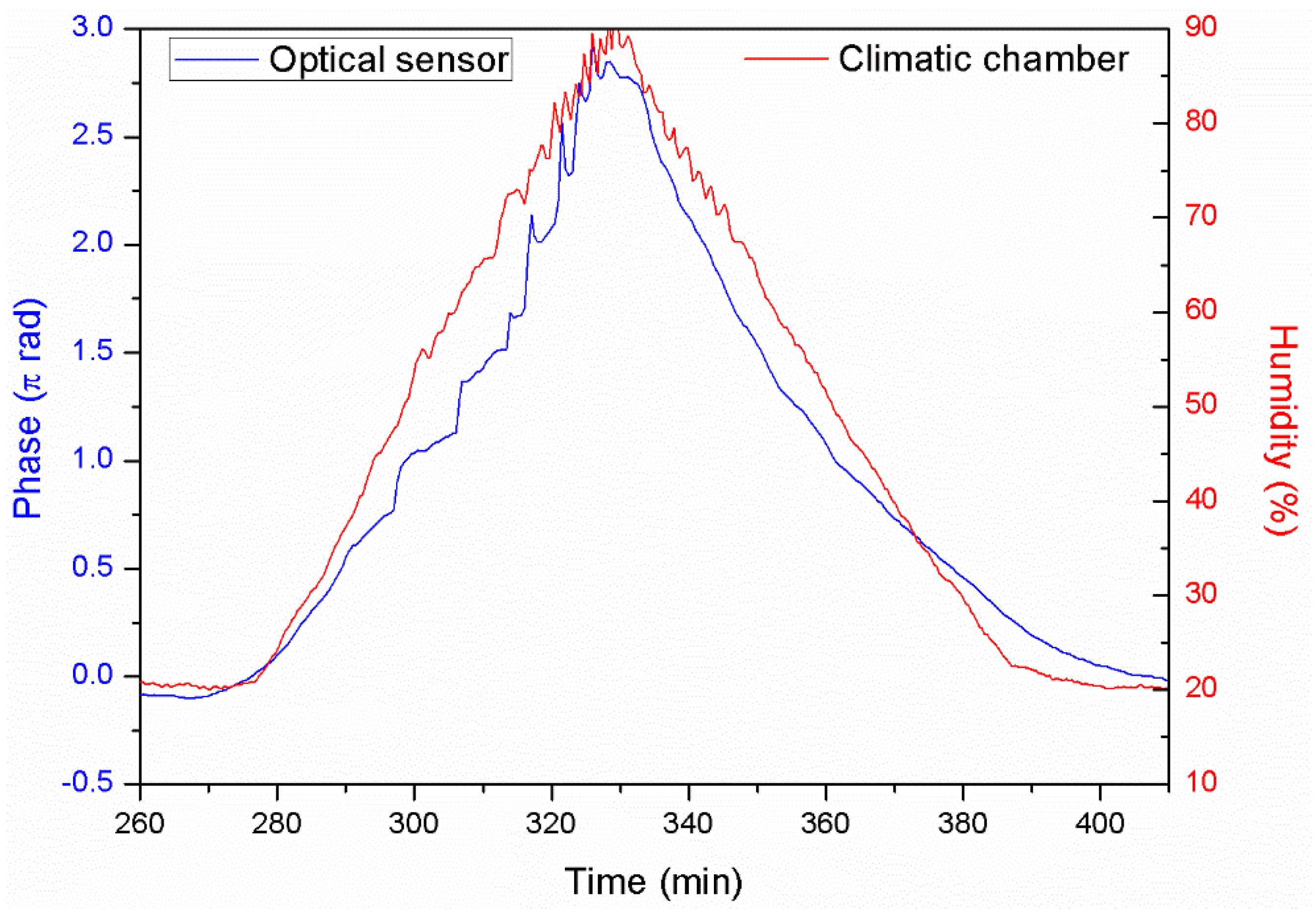
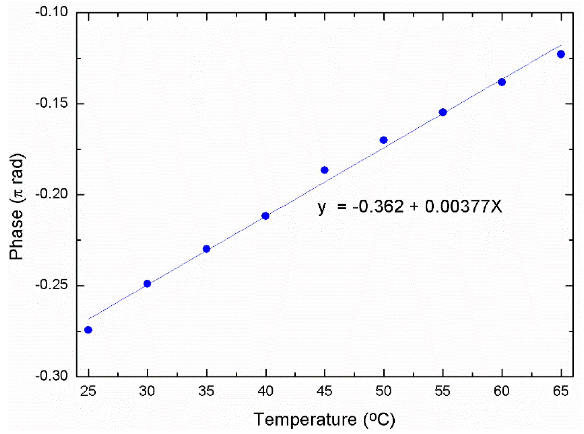
3.1. Temperature Monitoring and Compensation
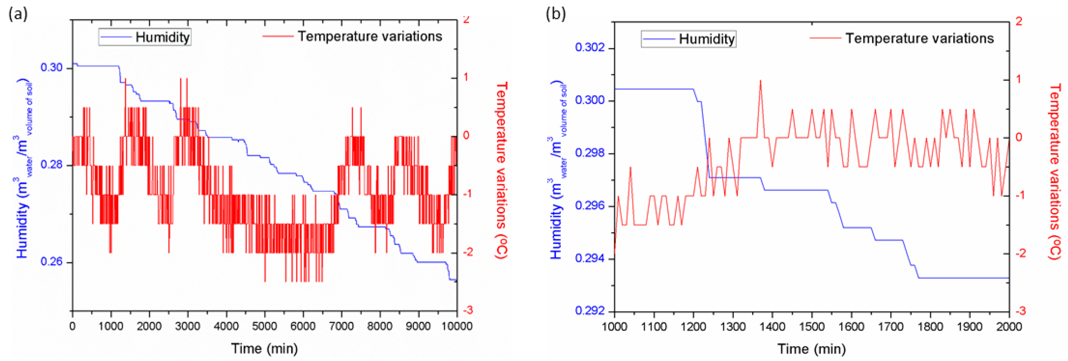
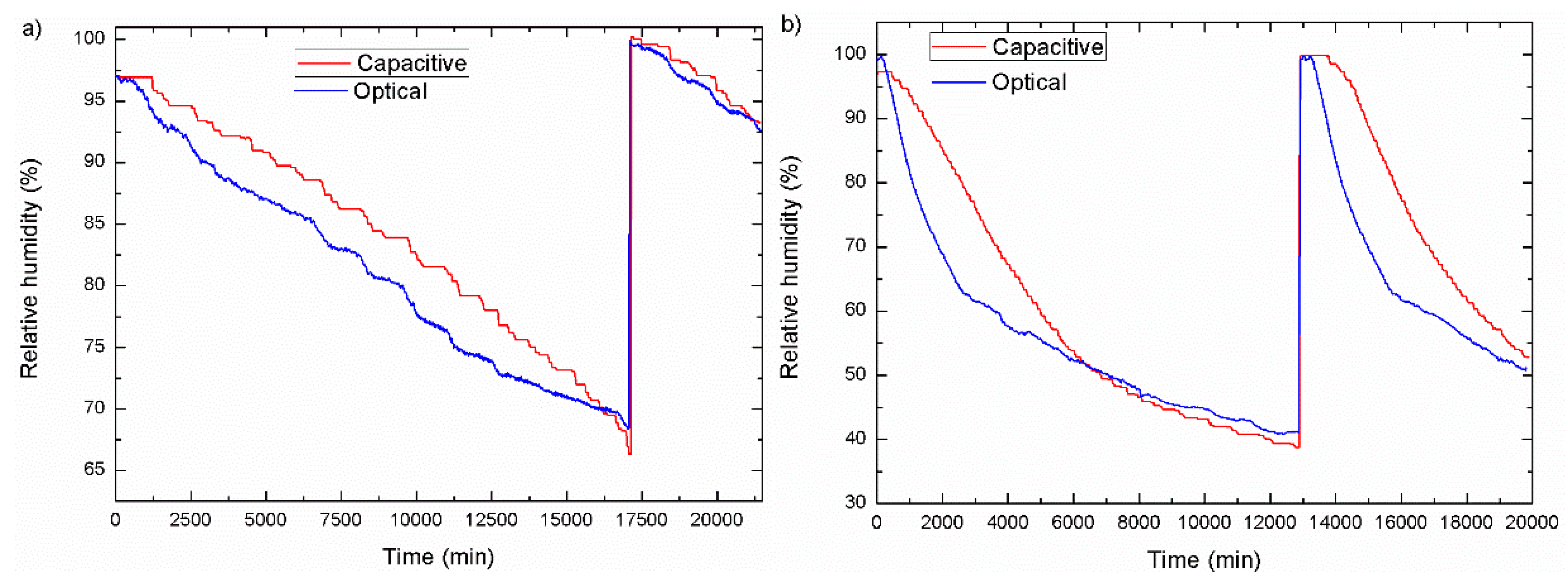
3.2. Dynamic Measurements
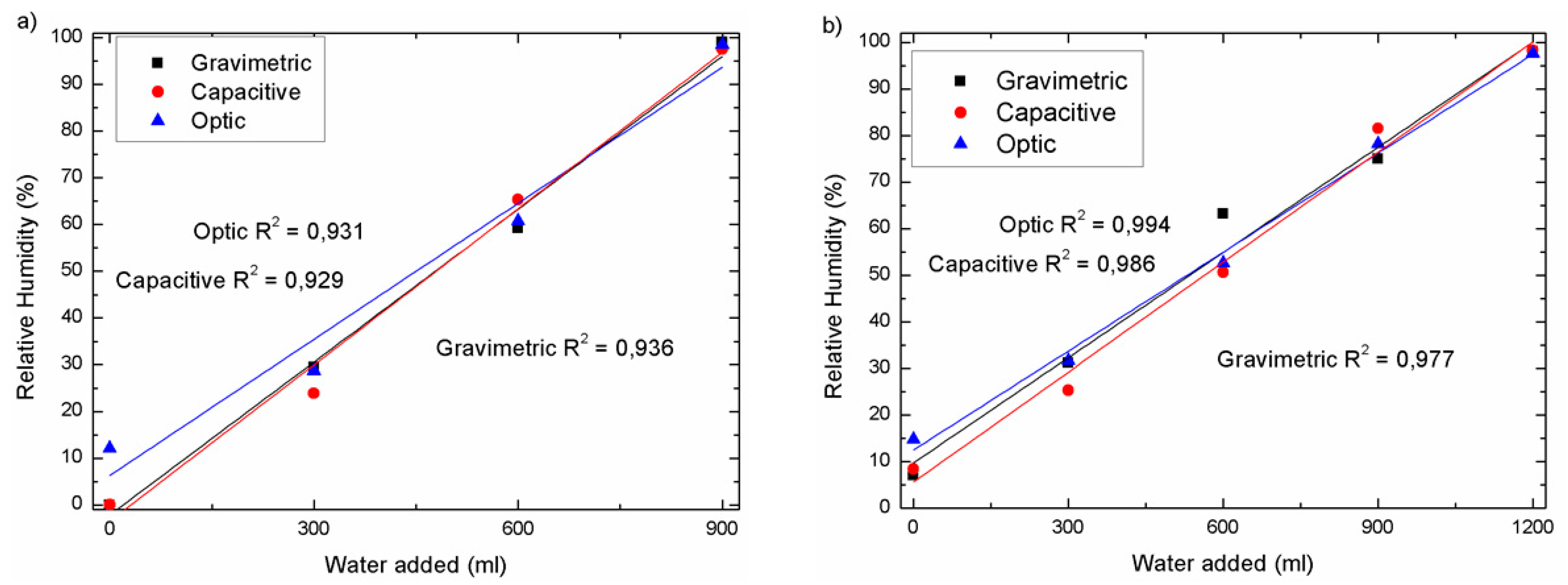
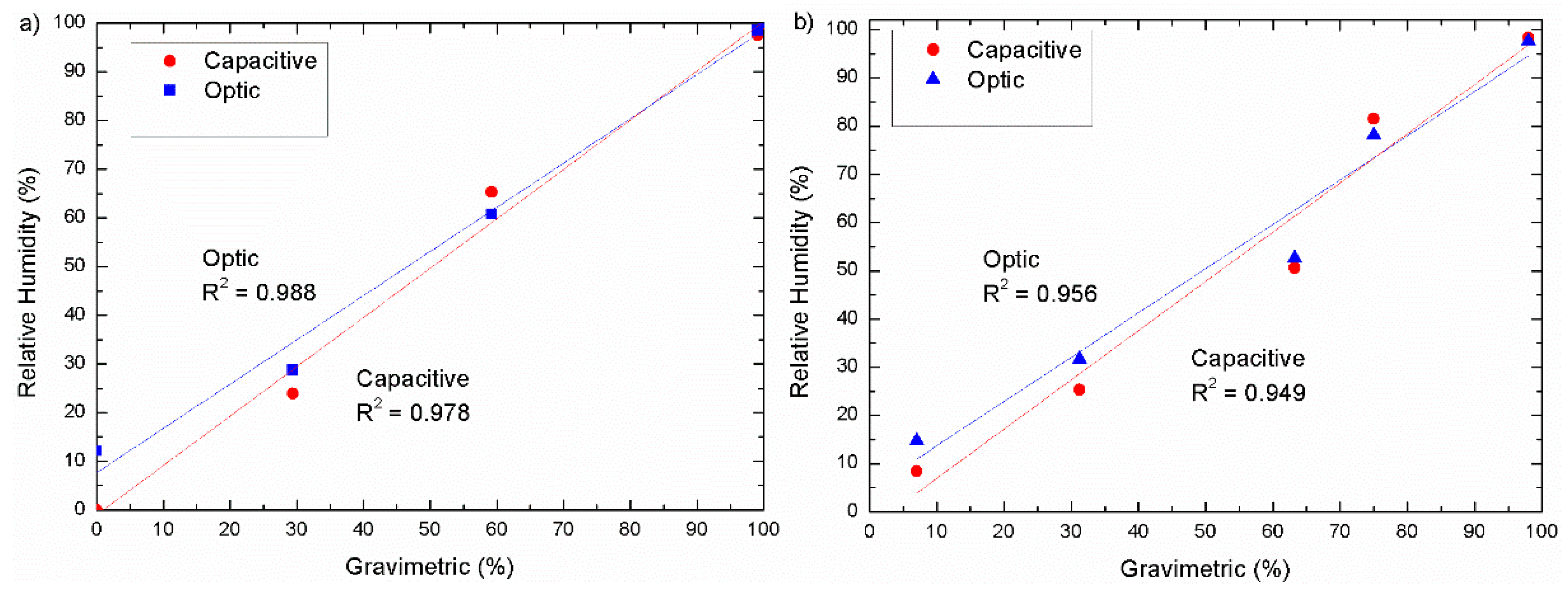
3.3. Point Measurements
4. Discussion
5. Conclusions
Author Contributions
Funding
Acknowledgments
Conflicts of Interest
References
- Rodríguez-Iturbe, I. Ecohydrology: A hydrologic perspective of climate-soil-vegetation dynamics. Water Resour. Res. 2000, 36, 3–9. [Google Scholar] [CrossRef]
- Eagleson, P.S. Ecohydrology; Cambridge University Press: Cambridge, UK, 2002. [Google Scholar]
- Bull, C.R. A review of sensing techniques which could be used to generate images of agricultural and food materials. Comput. Electron. Agric. 1993, 8, 1–29. [Google Scholar] [CrossRef]
- Nolz, R.; Kammerer, G.; Cepuder, P. Calibrating soil water potential sensors integrated into a Wireless monitoring network. Agric. Water Manag. 2013, 116, 12–20. [Google Scholar] [CrossRef]
- Loaiza-Usuga, J.C.; Pauwels, V.R.N. Utilización de sensores de humedad para la determinación del contenido de humedad del suelo: ecuaciones de calibración. Suelos Ecuatoriales SCCS 2008, 38, 24–33. [Google Scholar]
- WMO. Guide to Hydrological Practices. Available online: http://www.whycos.org/hwrp/guide/chapters/english/original/WMO168_Ed2008_Vol_I_Ch4_Up2008_en.pdf (accessed on 14 April 2008).
- Sharma, R.K.; Gupta, A.K. Continuous wave acoustic method for determination of moisture content in agricultural soil. Comput. Electron. Agric. 2010, 73, 105–111. [Google Scholar] [CrossRef]
- Christy, C.D. Real-time measurement of soil attributes using on-the-go near infrared reflectance spectroscopy. Comput. Electron. Agric. 2008, 61, 10–19. [Google Scholar] [CrossRef]
- Wang, Y.B.; Huang, T.Y.; Liu, J.; Lin, Z.L.; Li, S.H.; Wang, R.J.; Ge, Y.J. Soil pH value, organic matter and macronutrients contents prediction using optical diffuse reflectance spectroscopy. Comput. Electron. Agric. 2015, 111, 69–77. [Google Scholar] [CrossRef]
- Visconti, F.; De Paz, J.M.; Martínez, D.; Molina, M.J. Laboratory and field assessment of the capacitance sensors Decagon10HS and 5TE for estimating the water content of irrigated soils. Agric. Water Manag. 2014, 132, 111–119. [Google Scholar] [CrossRef]
- Topp, G.C. State of the art of measuring soil water content. Hydrol. Processes 2003, 17, 2993–2996. [Google Scholar] [CrossRef]
- Dobriyal, P.; Qureshi, A.; Badola, R.; Hussain, S.A. A review of the methods available for estimating soil moisture and its implications for water resource management. J. Hydrol. 2012, 458–459, 110–117. [Google Scholar] [CrossRef]
- Alwis, L.; Sun, T.; Grattan, K.T.V. Optical fibre-based sensor technology for humidity and moisture measurement: Review of recent progress. Measurement 2013, 46, 4052–4074. [Google Scholar] [CrossRef]
- Pinto, A.M.R.; Lopez-Amo, M. Photonic crystal fibers for sensing applications. J. Sens. 2012. [Google Scholar] [CrossRef]
- Monro, T.M.; Warren-Smith, S.; Schartner, E.P.; François, A.; Heng, S.; Ebendorff-Heidepriem, H.; Afshar, S. Sensing with suspended-core optical fibers. Opt. Fiber Technol. 2010, 16, 343–356. [Google Scholar] [CrossRef]
- Frazao, O.; Santos, J.L.; Araújo, F.M.; Ferreira, L.A. Optical sensing with photonic crystal fibers. Laser Photonics Rev. 2008, 2, 449–459. [Google Scholar] [CrossRef]
- Frazao, O.; Silva, S.F.O.; Viegas, J.; Baptista, J.M.; Santos, J.L.; Kobelke, J.; Schuster, K. All fiber Mach–Zehnder interferometer based on suspended twin-core fiber. IEEE Photonics Technol. Lett. 2010, 22, 1300–1302. [Google Scholar] [CrossRef]
- Webb, A.S.; Poletti, F.; Richardson, D.J.; Sahu, J.K. Suspended-core holey fiber for evanescent-field sensing. Opt. Eng. 2007, 46, 010503. [Google Scholar] [CrossRef]
- Aldaba, A.L.; Lopez-Torres, D.; Elosua, C.; Auguste, J.L.; Jamier, R.; Roy, P.; Arregui, F.J.; Lopez-Amo, M. SnO2-MOF-Fabry-Perot optical sensor for relative humidity measurements. Sens. Actuators B 2018, 257, 189–199. [Google Scholar] [CrossRef]
- Choi, H.Y.; Park, K.S.; Park, S.J.; Paek, U.C.; Lee, B.H.; Choi, E.S. Miniature fiber-optic high temperature sensor based on a hybrid structured Fabry–Perot interferometer. Opt. Lett. 2008, 33, 2455–2457. [Google Scholar] [CrossRef] [PubMed]
- Chen, L.H.; Li, T.; Chan, C.C.; Menon, R.; Balamurali, P.; Shaillender, M.; Neu, B.; Ang, X.M.; Zu, P.; Leong, K.C. Chitosan based fiber-optic Fabry–Perot humidity sensor. Sens. Actuators B 2012, 169, 167–172. [Google Scholar] [CrossRef]
- Mathew, J.; Semenova, Y.; Rajan, G.; Farrell, G. Humidity sensor based on photonic crystal fibre interferometer. Electron. Lett. 2010, 46, 1341–1343. [Google Scholar] [CrossRef]
- Arregui, F.J. Sensors Based on Nanostructured Materials; Springer: New York, NY, USA, 2009. [Google Scholar]
- Stowell, M.; Müller, J.; Ruske, M.; Lutz, M.; Linz, T. RF-superimposed DC and pulsed DC sputtering for deposition of transparent conductive oxides. Thin Solid Films 2007, 515, 7654–7657. [Google Scholar] [CrossRef]
- Ou, J.Z.; Yaacob, M.H.; Campbell, J.L.; Breedon, M.; Kalantar-Zadeh, K.; Wlodarski, W. H2 sensing performance of optical fiber coated with nano-platelet WO3 film. Sens. Actuators B 2012, 166, 1–6. [Google Scholar] [CrossRef]
- Dai, J.; Yang, M.; Yu, X.; Lu, H. Optical hydrogen sensor based on etched fiber Bragg grating sputtered with Pd/Ag composite film. Opt. Fiber Technol. 2013, 19, 26–30. [Google Scholar] [CrossRef]
- Laylor, H.M.; Calvert, S.; Taylor, T.; Schulz, W.; Lumsden, R.; Udd, E. Fiber optic grating moisture and humidity sensors. Proc. SPIE 2002, 4694, 210–217. [Google Scholar]
- Goh, L.S.; Kumekawa, N.; Watanabe, K.; Shinomiya, N. Hetero-core spliced optical fiber SPR sensor system for soil gravity water monitoring in agricultural environments. Comput. Electron. Agric. 2014, 101, 110–117. [Google Scholar] [CrossRef]
- Yeo, T.L.; Sun, T.; Grattan, K.T.V. Fibre-optic sensor technologies for humidity and moisture measurement. Sens. Actuators A 2008, 144, 280–295. [Google Scholar] [CrossRef]
- Sanchez, P.; Zamarreño, C.R.; Hernaez, M.; Matias, I.R.; Arregui, F.J. Optical fiber refractometers based on Lossy Mode Resonances by means of SnO2 sputtered coatings. Sens. Actuators B 2014, 202, 154–159. [Google Scholar] [CrossRef]
- Schmid, W. Consumption Measurements on SnO2 Sensors in Low and Normal Oxygen Concentration. Ph.D. Thesis, Universität Tübingen, Baden-wurttemberg state tubingen, Germany, March 2004. [Google Scholar]
- Yoshino, T.; Kurosawa, K.; Itoh, K.; Ose, T. Fiber-optic Fabry-Perot interferometer and its sensor applications. IEEE Trans. Microwave Theory Tech. 1982, 30, 1612–1621. [Google Scholar] [CrossRef]
- Leandro, D.; Bravo, M.; Ortigosa, A.; Lopez-Amo, M. Real-time FFT analysis for interferometric sensors multiplexing. J. Lightwave Technol. 2015, 33, 354–360. [Google Scholar] [CrossRef]
- Lopez-Aldaba, A.; Auguste, J.L.; Jamier, R.; Roy, P.; Lopez-Amo, M. Simultaneous strain and temperature multipoint sensor based on microstructured optical fiber. J. Lightwave Technol. 2018, 36, 910–916. [Google Scholar] [CrossRef]
- Aldaba, A.L.; Lopez-Torres, D.; Elosua, C.; Auguste, J.L.; Jamier, R.; Roy, P.; Arregui, F.J.; Lopez-Amo, M. Real Time Measuring System of Multiple Chemical Parameters Using Microstructured Optical Fibers Based Sensors. IEEE Sens. J. 2018, 18, 5343–5351. [Google Scholar] [CrossRef]
- Soil Survey Staff. Soil Taxonomy: A Basic System of Soil Classification for Making and Interpreting Soil Surveys, 2nd ed.; Natural Resources Conservation Service. U.S. Department of Agriculture: Washington, DC, USA, 1999.
- Wiederhold, P.R. Water Vapor Measurement: Methods and Instrumentation; CRC Press: Boca Raton, FL, USA, 1997. [Google Scholar]


| Comparison | Soil | Mean | Max |
|---|---|---|---|
| Optical—Capacitive Sensors | Soil1 | 3.5% | 5% |
| Soil2 | 3% | 6% | |
| Optical sensor—Gravimetric measurements | Soil1 | 1% | 1.5% |
| Soil2 | 3.5% | 9% |
© 2018 by the authors. Licensee MDPI, Basel, Switzerland. This article is an open access article distributed under the terms and conditions of the Creative Commons Attribution (CC BY) license (http://creativecommons.org/licenses/by/4.0/).
Share and Cite
Lopez Aldaba, A.; Lopez-Torres, D.; Campo-Bescós, M.A.; López, J.J.; Yerro, D.; Elosua, C.; Arregui, F.J.; Auguste, J.-L.; Jamier, R.; Roy, P.; et al. Comparison between Capacitive and Microstructured Optical Fiber Soil Moisture Sensors. Appl. Sci. 2018, 8, 1499. https://doi.org/10.3390/app8091499
Lopez Aldaba A, Lopez-Torres D, Campo-Bescós MA, López JJ, Yerro D, Elosua C, Arregui FJ, Auguste J-L, Jamier R, Roy P, et al. Comparison between Capacitive and Microstructured Optical Fiber Soil Moisture Sensors. Applied Sciences. 2018; 8(9):1499. https://doi.org/10.3390/app8091499
Chicago/Turabian StyleLopez Aldaba, Aitor, Diego Lopez-Torres, Miguel A. Campo-Bescós, José Javier López, David Yerro, César Elosua, Francisco J. Arregui, Jean-Louis Auguste, Raphael Jamier, Philippe Roy, and et al. 2018. "Comparison between Capacitive and Microstructured Optical Fiber Soil Moisture Sensors" Applied Sciences 8, no. 9: 1499. https://doi.org/10.3390/app8091499
APA StyleLopez Aldaba, A., Lopez-Torres, D., Campo-Bescós, M. A., López, J. J., Yerro, D., Elosua, C., Arregui, F. J., Auguste, J.-L., Jamier, R., Roy, P., & López-Amo, M. (2018). Comparison between Capacitive and Microstructured Optical Fiber Soil Moisture Sensors. Applied Sciences, 8(9), 1499. https://doi.org/10.3390/app8091499