Optical Comparison Operation for 8-Bit QPSK-Modulated Signal by Using Serially-Cascaded Delay Line Interferometer

Abstract
:1. Introduction
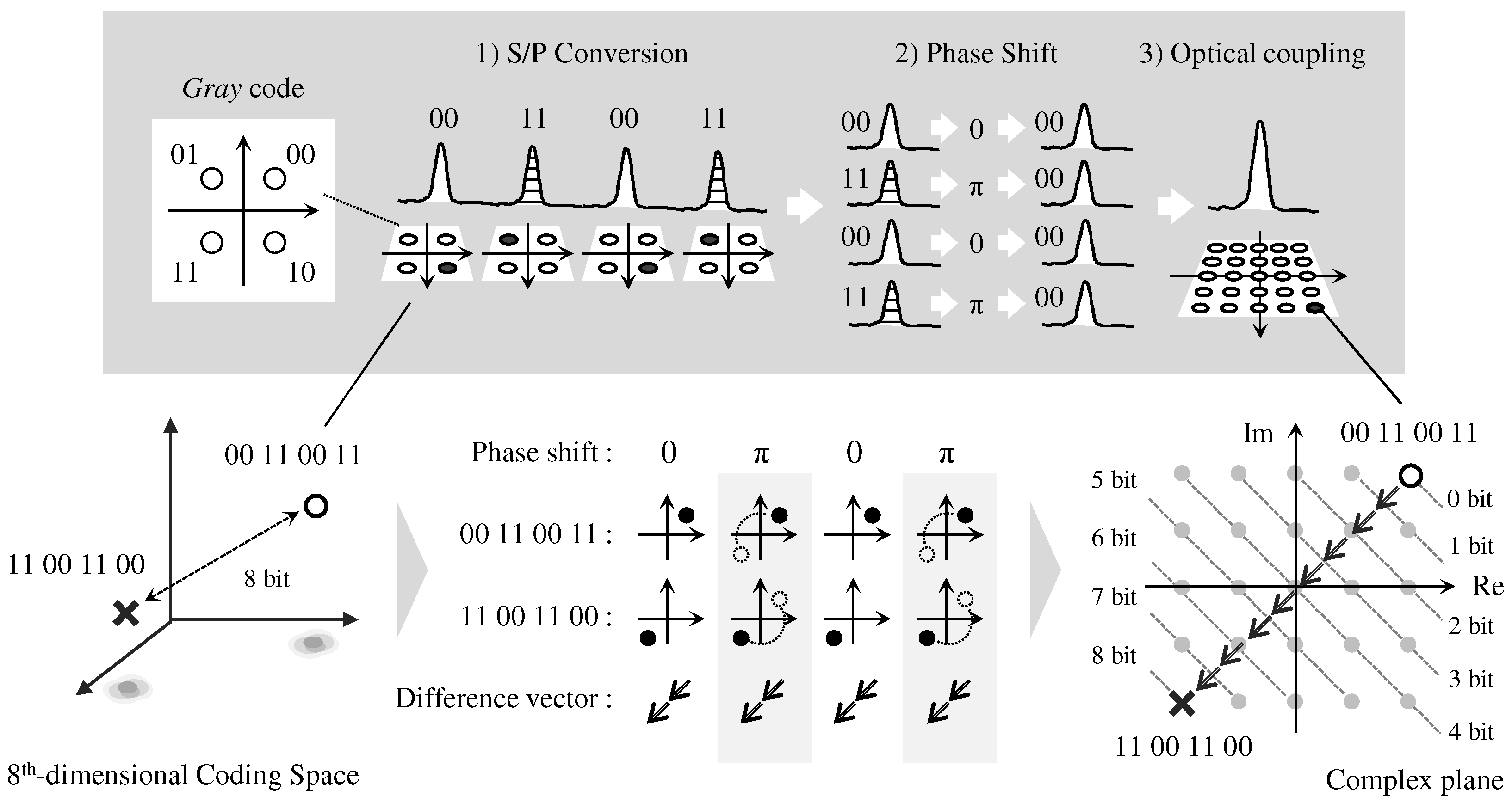
2. Operating Principles
- S/P conversion: to convert serially-successive symbols into four parallel symbols.
- Phase shift: to rotate the phases in each parallel symbol; the amounts of the phase rotation are determined according to the comparator code to convert their original constellations into a first quadrant in each QPSK symbol, which corresponds to a “00” constellation in code.
- Optical coupling: to yield a complex symbol from four parallel symbols optically.
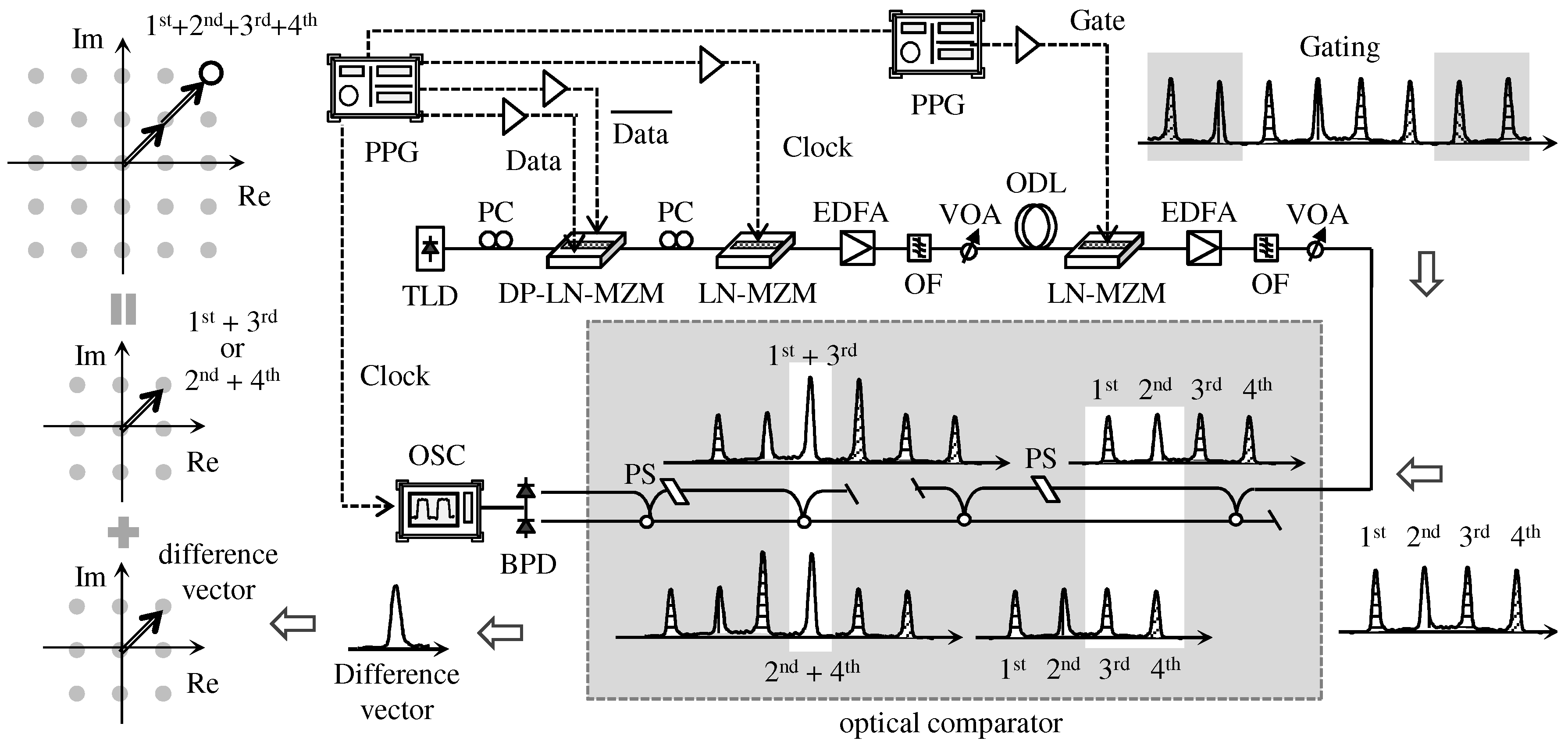
3. Experimental Setup
4. Experimental Results
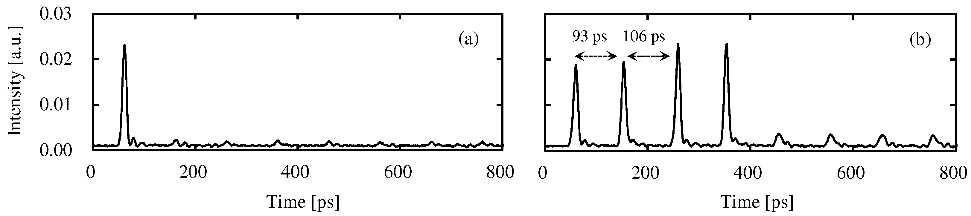
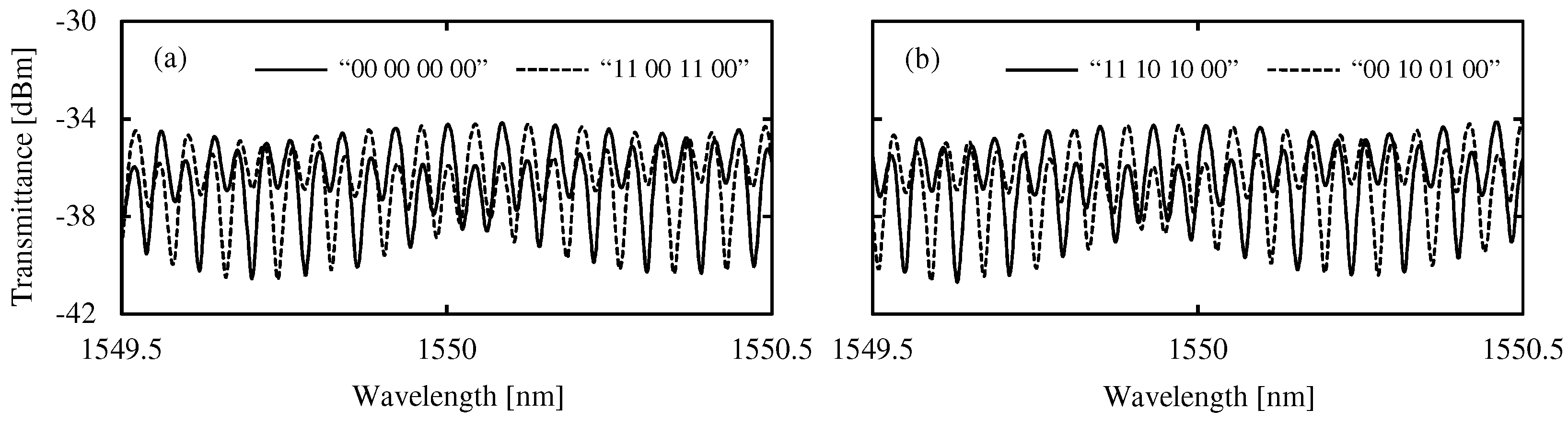
4.1. Fundamental Property
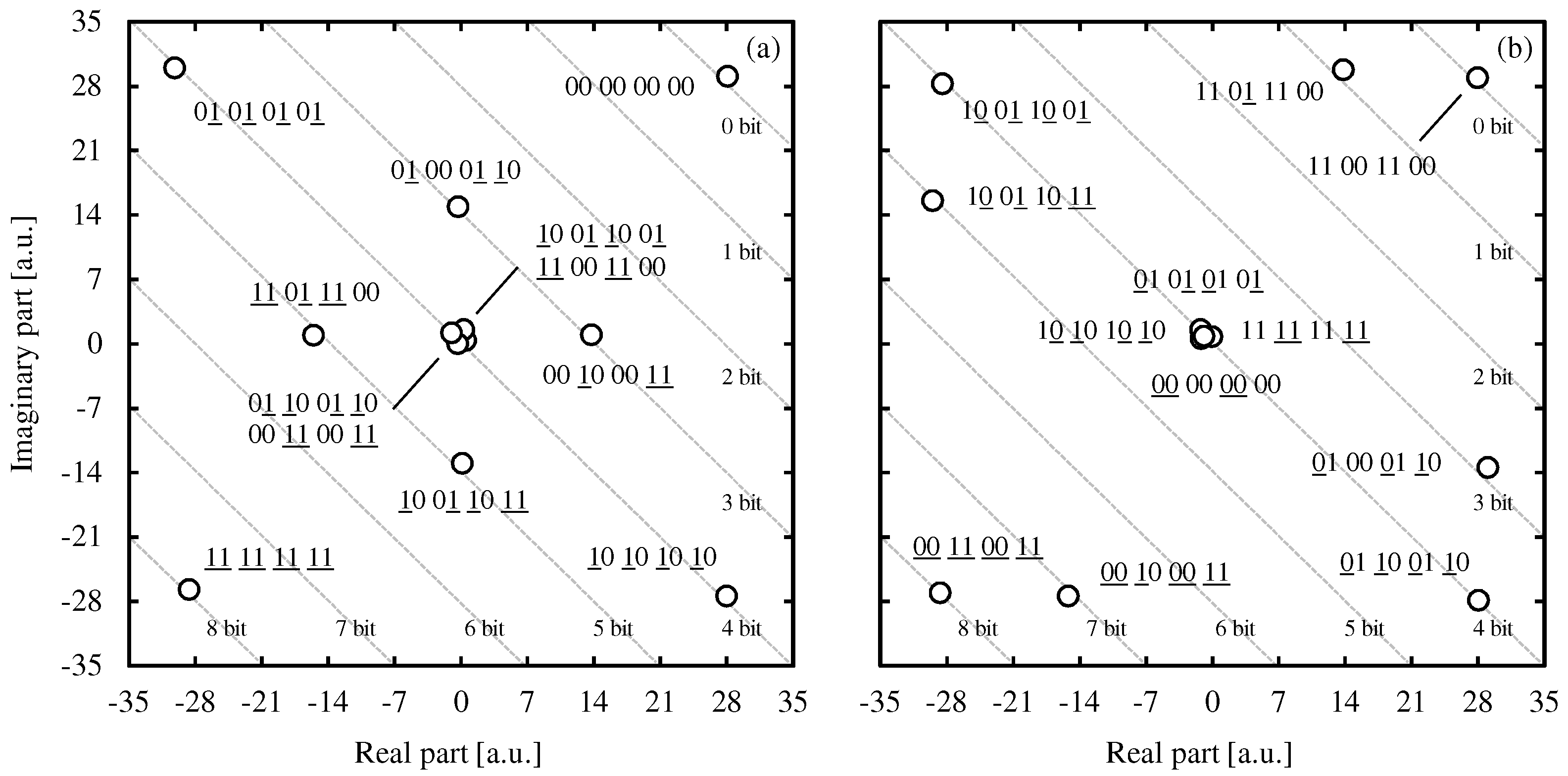
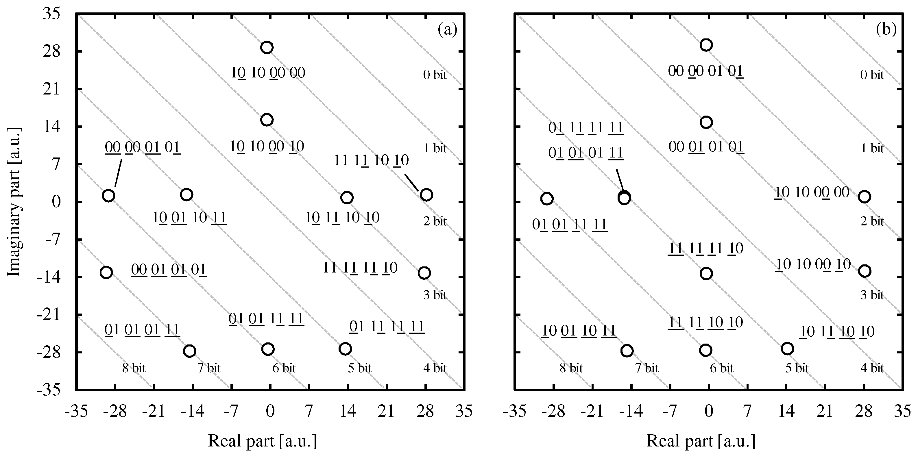
4.2. Optical Comparison Operation
- : 00 00 00 00;
- : 01 00 01 10, 00 10 00 11;
- : 10 01 10 01, 11 00 11 00, 01 10 01 10, 00 11 00 11, 01 01 01 01, 10 10 10 10;
- : 11 01 11 00, 10 01 10 11;
- : 11 11 11 11.
5. Discussion
Funding
Acknowledgments
Conflicts of Interest
Abbreviations
| OOK | On–Off Keying |
| PSK | Phase-Shift Keying |
| QPSK | Quadrature Phase-Shift Keying |
| DLI | Delay Line Interferometer |
| TLD | Tunable Laser Diode |
| PPG | Pulse Pattern Generator |
| LN-MZI | Lithium-Niobate Mach-Zehnder Modulator |
| PRBS | Pseudo Random Binary Sequence |
| RZ | Rreturn-to-Zero |
| FSR | Free Spectrum Range |
| BPD | Balanced Photo Detector |
| FWHM | Full Width at Half Maximum |
| ASE | Amplified Spontaneous Emission |
References
- Urata, R.; Nakahara, T.; Takenouchi, H.; Segawa, T.; Ishikawa, H.; Ohki, A.; Sugiyama, H.; Nishihara, S.; Takahashi, R. 4 × 4 optical packet switching of asynchronous burst optical packets with a prototype, 4 × 4 label processing and switching sub-system. Opt. Express 2010, 18, 15283–15288. [Google Scholar] [CrossRef] [PubMed]
- Segawa, T.; Ibrahim, S.; Nakahara, T.; Muranaka, Y.; Takahashi, R. Low-Power Optical Packet Switching for 100-Gb/s Burst Optical Packets With a Label Processor and 8 × 8 Optical Switch. J. Lightw. Technol. 2016, 34, 1844–1850. [Google Scholar] [CrossRef]
- Martinez, J.M.; Herrera, J.; Ramos, F.; Marti, J. All-Optical Address Recognition Scheme for Label-Swapping Networks. IEEE Photonics Technol. Lett. 2006, 18, 151–153. [Google Scholar] [CrossRef]
- Kehayas, E.; Seoane, J.; Liu, Y.; Martinez, J.M.; Herrera, J.; Holm-Nielsen, P.V.; Zhang, S.; McDougall, R.; Maxwell, G.; Ramos, F.; et al. All-Optical Network Subsystems Using Integrated SOA-Based Optical Gates and Flip-Flops for Label-Swapped Networks. IEEE Photonics Technol. Lett. 2006, 18, 1750–1752. [Google Scholar] [CrossRef]
- Suzuki, M.; Uenohara, H. Investigation of all-optical error detection circuit using SOA-MZI-based XOR gates at 10 Gbit/s. Electron. Lett. 2009, 45, 224–225. [Google Scholar] [CrossRef]
- Aikawa, Y.; Shimizu, S.; Uenohara, H. Demonstration of All-Optical Divider Circuit Using SOA-MZI-Type XOR Gate and Feedback Loop for Forward Error Detection. J. Lightw. Technol. 2011, 15, 2259–2266. [Google Scholar] [CrossRef]
- Aikawa, Y.; Uenohara, H. Demonstration of Optical FEC Coding Scheme with Convolutional Code Consisting of a Single Source. IEEE Photonics Technol. Lett. 2017, 29, 165–168. [Google Scholar] [CrossRef]
- Kostinski, N.; Kravtsov, K.; Prucnal, P.R. Demonstration of an All-Optical OCDMA Encryption and Decryption System With Variable Two-Code Keying. IEEE Photonics Technol. Lett. 2008, 20, 2045–2047. [Google Scholar] [CrossRef]
- Fok, M.P.; Prucnal, P.R. All-optical encryption based on interleaved waveband switching modulation for optical network security. Opt. Lett. 2009, 34, 1315–1317. [Google Scholar] [CrossRef] [PubMed]
- Kim, J.H.; Byun, Y.T.; Jhon, Y.M.; Lee, S.; Woo, D.H.; Kim, S.H. All-optical half adder using semiconductor optical amplifier based devices. Opt. Commun. 2003, 218, 345–349. [Google Scholar] [CrossRef]
- Kumar, S.; Willner, A.E.; Gurkan, D.; Parameswaran, K.R.; Fejer, M.M. All-optical half adder using an SOA and a PPLN waveguide for signal processing in optical networks. Opt. Express 2006, 14, 10255–10260. [Google Scholar] [CrossRef] [PubMed]
- Poustie, A.J.; Blow, K.J.; Kelly, A.E.; Manning, R.J. All-optical full adder with bit-differential delay. Opt. Commun. 1999, 168, 89–93. [Google Scholar] [CrossRef]
- Martinez, J.M.; Herrera, J.; Ramos, F.; Marti, J. All-optical correlation employing single logic XOR gate with feedback. Electron. Lett. 2006, 42, 1–2. [Google Scholar] [CrossRef]
- Rasras, M.S.; Kang, I.; Dinu, M.; Jaques, J.; Dutta, N.; Piccirilli, A.; Cappuzzo, M.A.; Chen, E.Y.; Gomez, L.T.; Foy, A.W.; et al. A Programmable 8-bit Optical Correlator Filter for Optical Bit Pattern Recognition. IEEE Photonics Technol. Lett. 2008, 20, 694–696. [Google Scholar] [CrossRef]
- Khaleghi, S.; Yilmaz, O.F.; Chitgarha, M.R.; Tur, M.; Ahmed, N.; Nuccio, S.R.; Fazal, I.M.; Wu, X.; Haney, M.W.; Langrock, C.; et al. High-Speed Correlation and Equalization Using a Continuously Tunable All- Optical Tapped Delay Line. IEEE Photonics J. 2012, 4, 1220–1235. [Google Scholar] [CrossRef]
- Chitgarha, M.R.; Khaleghi, S.; Yilmaz, O.F.; Tur, M.; Haney, M.W.; Lan-grock, C.; Fejer, M.M.; Willner, A.E. Coherent correlator and equalizer using a reconfigurable all-optical tapped delay line. Opt. Lett. 2013, 38, 2271–2273. [Google Scholar] [CrossRef] [PubMed]
- Wang, Y.; Zhang, X.; Dong, J.; Huang, D. Simultaneous demonstration on all-optical digital encoder and comparator at 40 Gb/s with semiconductor optical amplifiers. Opt. Lett. 2007, 15, 15080–15085. [Google Scholar] [CrossRef]
- Scaffardi, M.; Lazzeri, E.; Poti, L.; Bogoni, A. All-Optical Comparator Based on Cross Gain Modulation in Semiconductor Optical Amplifiers. In Proceedings of the Optical Fiber Communication Conference/National Fiber Optic Engineers Conference (OFC/NFOEC) 2008, San Diego, CA, USA, 24–28 February 2008; p. JWA79. [Google Scholar]
- Li, P.; Sang, L.; Zhao, D.; Fan, Y.; Shore, K.A.; Wang, Y.; Wang, A. All-Optical Comparator With a Step-Like Transfer Function. J. Lightw. Technol. 2017, 35, 5034–5040. [Google Scholar] [CrossRef]
- Nakarmi, B.; Uddin, M.R.; Won, Y.H. Realization of All-Optical Digital Comparator Using Single Mode Fabry–Perot Laser Diodes. J. Lightw. Technol. 2011, 29, 3015–3021. [Google Scholar] [CrossRef]
- Yang, L.; Guo, C.; Zhu, W.; Zhang, L.; Sun, C. Demonstration of a Directed Optical Comparator Based on Two Cascaded Microring Resonators. IEEE Photonics Technol. Lett. 2015, 27, 809–812. [Google Scholar] [CrossRef]
- Weinstock, T.; Ehrlichman, Y.; Amrani, O. Electrooptical Comparator: From Formula to Implementation. J. Lightw. Technol. 2017, 35, 4056–4066. [Google Scholar] [CrossRef]
- Aikawa, Y. Optical Comparator for 4-Bit and 6-Bit QPSK-Modulated Signals by Using Optical Delayed Interferometer. IEEE Photonics J. 2018, 10, 7800711. [Google Scholar] [CrossRef]


| Comparator Code | Applied Voltage in PS (V) | Phase Shifts in Each Symbol | ||||
|---|---|---|---|---|---|---|
| 5GHz DLI | 10GHz DLI | 1st | 2nd | 3rd | 4th | |
| 00 00 00 00 | 2.3 (=0) | 0.6 (=0) | 0 | 0 | 0 | 0 |
| 11 00 11 00 | 2.3 (=0) | 1.8 (=) | 0 | 0 | ||
| 11 10 10 00 | 2.8 (=/2) | 1.2 (=/2) | /2 | /2 | 0 | |
| 00 10 01 00 | 2.8 (=/2) | 2.4 (=3/2) | 0 | /2 | 3/2 | 0 |
© 2018 by the author. Licensee MDPI, Basel, Switzerland. This article is an open access article distributed under the terms and conditions of the Creative Commons Attribution (CC BY) license (http://creativecommons.org/licenses/by/4.0/).
Share and Cite
Aikawa, Y. Optical Comparison Operation for 8-Bit QPSK-Modulated Signal by Using Serially-Cascaded Delay Line Interferometer. Appl. Sci. 2018, 8, 1440. https://doi.org/10.3390/app8091440
Aikawa Y. Optical Comparison Operation for 8-Bit QPSK-Modulated Signal by Using Serially-Cascaded Delay Line Interferometer. Applied Sciences. 2018; 8(9):1440. https://doi.org/10.3390/app8091440
Chicago/Turabian StyleAikawa, Yohei. 2018. "Optical Comparison Operation for 8-Bit QPSK-Modulated Signal by Using Serially-Cascaded Delay Line Interferometer" Applied Sciences 8, no. 9: 1440. https://doi.org/10.3390/app8091440
APA StyleAikawa, Y. (2018). Optical Comparison Operation for 8-Bit QPSK-Modulated Signal by Using Serially-Cascaded Delay Line Interferometer. Applied Sciences, 8(9), 1440. https://doi.org/10.3390/app8091440