Design and Experimental Investigation of a Piezoelectric Rotation Energy Harvester Using Bistable and Frequency Up-Conversion Mechanisms


Abstract
1. Introduction
2. Design and Modeling
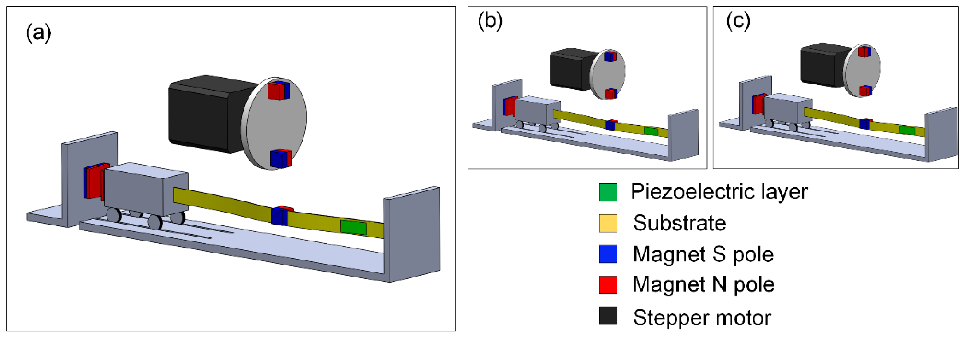
2.1. Design
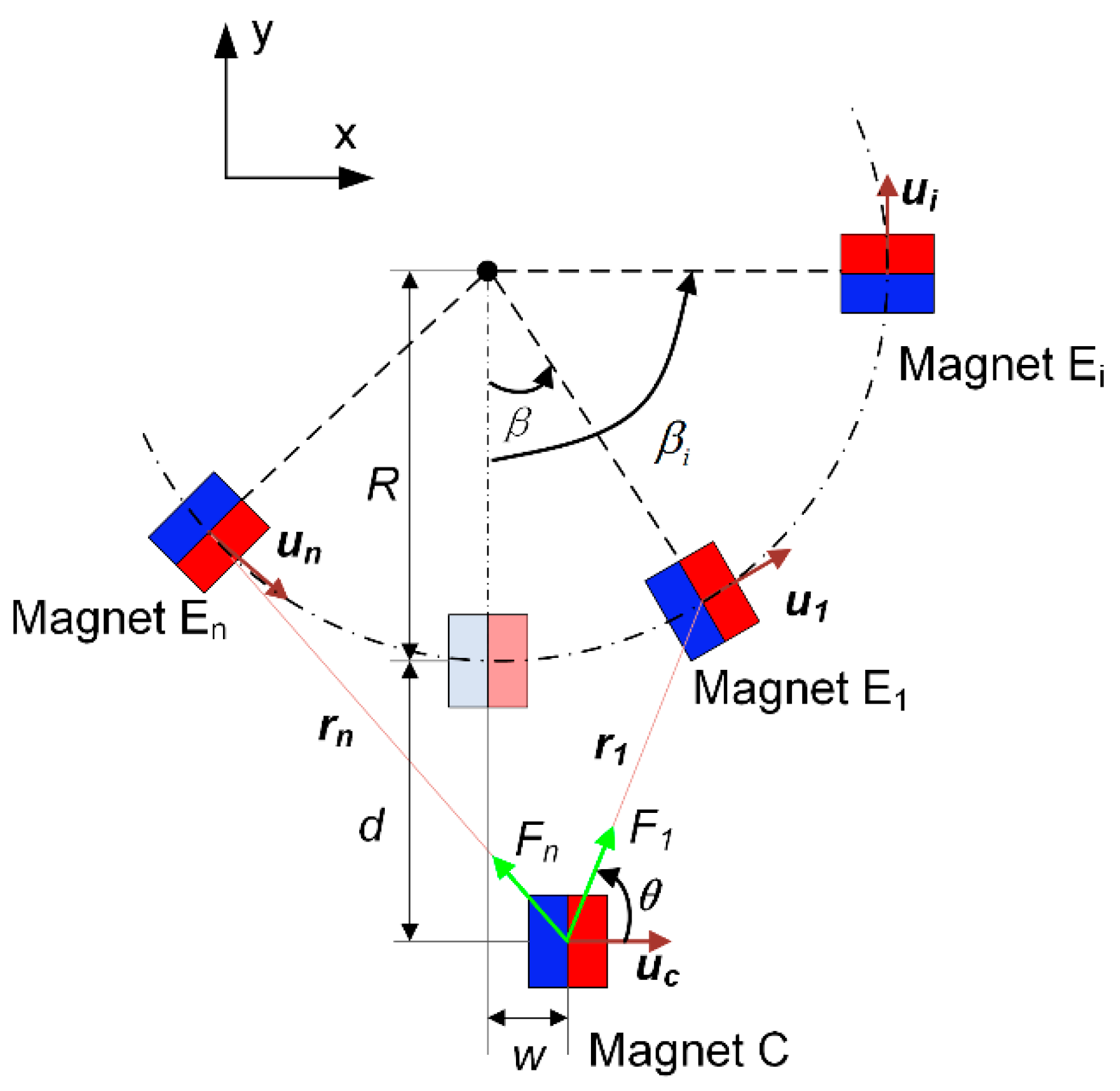
2.2. Modeling
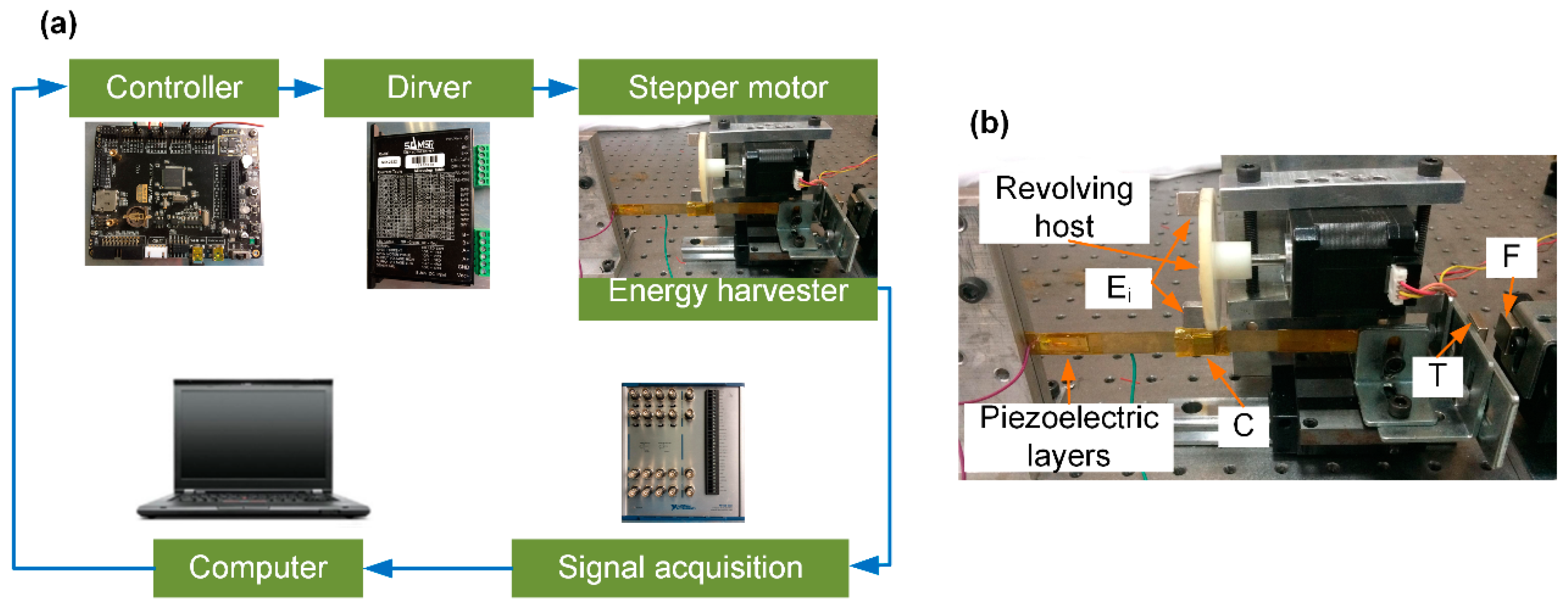
3. Experiment Setup
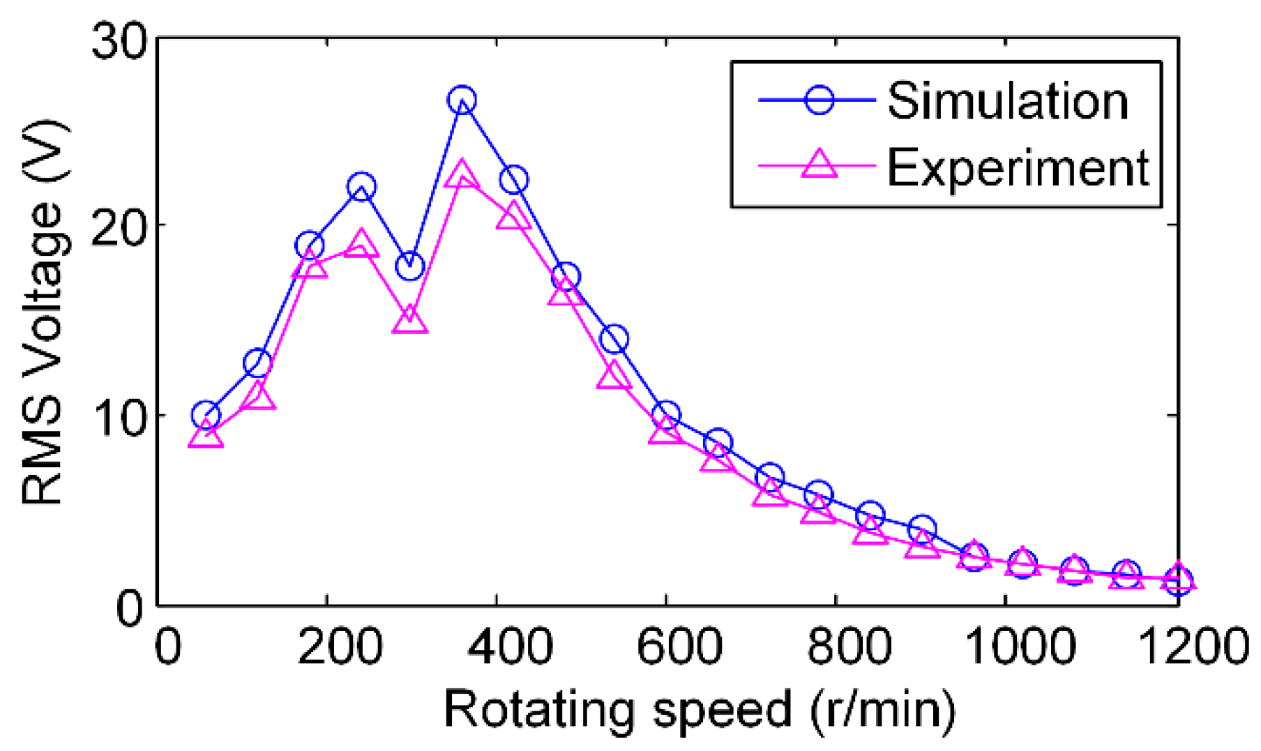
4. Results and Discussion
5. Conclusions
Author Contributions
Funding
Conflicts of Interest
References
- Yang, Z.; Zhou, S.; Zu, J.; Inman, D. High-Performance Piezoelectric Energy Harvesters and Their Applications. Joule 2018, 2, 642–697. [Google Scholar] [CrossRef]
- Xu, Z.; Shan, X.; Chen, D.; Xie, T. A Novel Tunable Multi-Frequency Hybrid Vibration Energy Harvester Using Piezoelectric and Electromagnetic Conversion Mechanisms. Appl. Sci. 2016, 6, 10. [Google Scholar] [CrossRef]
- Siddique, A.R.M.; Mahmud, S.; Heyst, B.V. A comprehensive review on vibration based micro power generators using electromagnetic and piezoelectric transducer mechanisms. Energy Convers. Manag. 2015, 106, 728–747. [Google Scholar] [CrossRef]
- Rantz, R.; Halim, M.A.; Xue, T.; Zhang, Q.; Gu, L.; Yang, K.; Roundy, S. Architectures for wrist-worn energy harvesting. Smart Mater. Struct. 2018, 27, 044001. [Google Scholar] [CrossRef]
- Zhang, Y.; Wang, T.; Luo, A.; Hu, Y.; Li, X.; Wang, F. Micro electrostatic energy harvester with both broad bandwidth and high normalized power density. Appl. Energy 2018, 212, 362–371. [Google Scholar] [CrossRef]
- Wu, C.; Liu, R.; Wang, J.; Zi, Y.; Lin, L.; Wang, Z.L. A spring-based resonance coupling for hugely enhancing the performance of triboelectric nanogenerators for harvesting low-frequency vibration energy. Nano Energy 2017, 32, 287–293. [Google Scholar] [CrossRef]
- Fan, K.; Tan, Q.; Zhang, Y.; Liu, S.; Cai, M.; Zhu, Y. A monostable piezoelectric energy harvester for broadband low-level excitations. Appl. Phys. Lett. 2018, 112, 123901. [Google Scholar] [CrossRef]
- Naseer, R.; Dai, H.L.; Abdelkefi, A.; Wang, L. Piezomagnetoelastic energy harvesting from vortex-induced vibrations using monostable characteristics. Appl. Energy 2017, 203, 142–153. [Google Scholar] [CrossRef]
- Stanton, S.C.; McGehee, C.C.; Mann, B.P. Nonlinear dynamics for broadband energy harvesting: Investigation of a bistable piezoelectric inertial generator. Phys. D Nonlinear Phenom. 2010, 239, 640–653. [Google Scholar] [CrossRef]
- Erturk, A.; Inman, D.J. Broadband piezoelectric power generation on high-energy orbits of the bistable Duffing oscillator with electromechanical coupling. J. Sound Vib. 2011, 330, 2339–2353. [Google Scholar] [CrossRef]
- Emam, S.A.; Inman, D.J. A Review on Bistable Composite Laminates for Morphing and Energy Harvesting. Appl. Mech. Rev. 2015, 67, 060803. [Google Scholar] [CrossRef]
- Masana, R.; Daqaq, M.F. Relative performance of a vibratory energy harvester in mono- and bi-stable potentials. J. Sound Vib. 2011, 330, 6036–6052. [Google Scholar] [CrossRef]
- Kitio Kwuimy, C.A.; Litak, G.; Borowiec, M.; Nataraj, C. Performance of a piezoelectric energy harvester driven by air flow. Appl. Phys. Lett. 2012, 100, 024103. [Google Scholar] [CrossRef]
- Harne, R.L.; Wang, K.W. Axial suspension compliance and compression for enhancing performance of a nonlinear vibration energy harvesting beam system. J. Vib. Acoust. 2016, 138, 011004. [Google Scholar] [CrossRef]
- Erturk, A.; Hoffmann, J.; Inman, D.J. A piezomagnetoelastic structure for broadband vibration energy harvesting. Appl. Phys. Lett. 2009, 94, 254102. [Google Scholar] [CrossRef]
- Arrieta, A.F.; Hagedorn, P.; Erturk, A.; Inman, D.J. A piezoelectric bistable plate for nonlinear broadband energy harvesting. Appl. Phys. Lett. 2010, 97, 104102. [Google Scholar] [CrossRef]
- Leland, E.S.; Wright, P.K. Resonance tuning of piezoelectric vibration energy scavenging generators using compressive axial preload. Smart Mater. Struct. 2006, 15, 1413–1420. [Google Scholar] [CrossRef]
- Masana, R.; Daqaq, M.F. Electromechanical Modeling and Nonlinear Analysis of Axially Loaded Energy Harvesters. J. Vib. Acoust. 2011, 133, 011007. [Google Scholar] [CrossRef]
- Zhu, Y.; Zu, J. A magnet-induced buckled-beam piezoelectric generator for wideband vibration-based energy harvesting. J. Intell. Mater. Syst. Struct. 2014, 25, 1890–1901. [Google Scholar] [CrossRef]
- Liu, W.; Formosa, F.; Badel, A.; Agbossou, A.; Hu, G. Investigation of a buckled beam generator with elastic clamp boundary. Smart Mater. Struct. 2016, 25, 115045. [Google Scholar] [CrossRef]
- Zhang, J.; Zhang, J.; Shu, C.; Fang, Z. Enhanced piezoelectric wind energy harvesting based on a buckled beam. Appl. Phys. Lett. 2017, 110, 103903. [Google Scholar] [CrossRef]
- Jiang, X.; Zou, H.; Zhang, W. Design and analysis of a multi-step piezoelectric energy harvester using buckled beam friven by magentic excitation. Energy Convers. Manag. 2017, 145, 129–137. [Google Scholar] [CrossRef]
- Gafforelli, G.; Corigliano, A.; Xu, R.; Kim, S. Experimental verification of a bridge-shaped, nonlinear vibration energy harvester. Appl. Phys. Lett. 2014, 105, 203901. [Google Scholar] [CrossRef]
- Renaud, M.; Fiorini, P.; van Schaijk, R.; van Hoof, C. Harvesting energy from the motion of human limbs: The design and analysis of an impact-based piezoelectric generator. Smart Mater. Struct. 2009, 18, 035001. [Google Scholar] [CrossRef]
- Wei, S.; Hu, H.; He, S. Modeling and experimental investigation of an impact-driven piezoelectric energy harvester from human motion. Smart Mater. Struct. 2013, 22, 105020. [Google Scholar] [CrossRef]
- Tang, Q.C.; Yang, Y.L.; Li, X. Bi-stable frequency up-conversion piezoelectric energy harvester driven by non-contact magnetic repulsion. Smart Mater. Struct. 2011, 20, 125011. [Google Scholar] [CrossRef]
- Pillatsch, P.; Yeatman, E.M.; Holmes, A.S. A piezoelectric frequency up-converting energy harvester with rotating proof mass for human body applications. Sens. Actuators A Phys. 2014, 206, 178–185. [Google Scholar] [CrossRef]
- Ramezanpour, R.; Nahvi, H.; Ziaei-Rad, S. A vibration-based energy harvester suitable for low-frequency, high-amplitude environments: Theoretical and experimental investigations. J. Intell. Mater. Syst. Struct. 2015, 27, 642–665. [Google Scholar] [CrossRef]
- Gu, L.; Livermore, C. Compact passively self-tuning energy harvesting for rotating applications. Smart Mater. Struct. 2012, 21, 015002. [Google Scholar] [CrossRef]
- Guan, M.; Liao, W.H. Design and analysis of a piezoelectric energy harvester for rotational motion system. Energy Convers. Manag. 2016, 111, 239–244. [Google Scholar] [CrossRef]
- Febbo, M.; Machado, S.P.; Gatti, C.D.; Ramirez, J.M. An out-of-plane rotational energy harvesting system for low frequency environments. Energy Convers. Manag. 2017, 152, 166–175. [Google Scholar] [CrossRef]
- Karami, M.A.; Farmer, J.R.; Inman, D.J. Parametrically excited nonlinear piezoelectric compact wind turbine. Renew. Energy 2013, 50, 977–987. [Google Scholar] [CrossRef]
- Kan, J.; Fan, C.; Wang, S.; Zhang, Z.; Wen, J.; Huang, L. Study on a piezo-windmill for energy harvesting. Renew. Energy 2016, 97, 210–217. [Google Scholar] [CrossRef]
- Fu, H.; Yeatman, E.M. Rotational energy harvesting using bi-stability and frequency up-conversion for low-power sensing applications: Theoretical modelling and experimental validation. Mech. Syst. Signal. Process 2018, in press. [Google Scholar] [CrossRef]
- Zou, H.X.; Zhang, W.M.; Li, W.B.; Gao, Q.H.; Wei, K.X.; Peng, Z.K.; Meng, G. Design, modeling and experimental investigation of a magnetically coupled flextensional rotation energy harvester. Smart Mater. Struct. 2017, 26, 115023. [Google Scholar] [CrossRef]
- Xie, Z.; Kitio Kwuimy, C.A.; Wang, Z.; Huang, W. A piezoelectric energy harvester for broadband rotational excitation using buckled beam. AIP Adv. 2018, 8, 015125. [Google Scholar] [CrossRef]
- Yung, K.W.; Landecker, P.B.; Villani, D.D. An analytic solution for the force between two magnetic dipoles. Magn. Electr. Sep. 1998, 6, 39–52. [Google Scholar] [CrossRef]


| Parameter Description | Value |
|---|---|
| Substrate | |
| Length l | 155 mm |
| Width bs | 10 mm |
| Thickness hs | 0.4 mm |
| Density ρs | 8800 kg/m3 |
| Young’s modulus Es | 110 Gpa |
| Piezoelectric layers | |
| Length lp | 22 mm |
| Width bp | 8 mm |
| Thickness hp | 0.24 mm |
| Density ρp | 7800 kg/m3 |
| Young’s modulus Ep | 70 Gpa |
| Piezoelectric constant d31 | −285 × 10−12 C/N |
| Relative permittivity | 3200 |
| Magnet | |
| Dimension of tip and fixed magnets a × b × c | 15 × 15 × 5 mm3 |
| Dimension of exciting and center magnets A × B × C | 10 × 10 × 10 mm3 |
| Magnet’s residual flux density Br | 1.2 T |
© 2018 by the authors. Licensee MDPI, Basel, Switzerland. This article is an open access article distributed under the terms and conditions of the Creative Commons Attribution (CC BY) license (http://creativecommons.org/licenses/by/4.0/).
Share and Cite
Xie, Z.; Xiong, J.; Zhang, D.; Wang, T.; Shao, Y.; Huang, W. Design and Experimental Investigation of a Piezoelectric Rotation Energy Harvester Using Bistable and Frequency Up-Conversion Mechanisms. Appl. Sci. 2018, 8, 1418. https://doi.org/10.3390/app8091418
Xie Z, Xiong J, Zhang D, Wang T, Shao Y, Huang W. Design and Experimental Investigation of a Piezoelectric Rotation Energy Harvester Using Bistable and Frequency Up-Conversion Mechanisms. Applied Sciences. 2018; 8(9):1418. https://doi.org/10.3390/app8091418
Chicago/Turabian StyleXie, Zhengqiu, Jitao Xiong, Deqi Zhang, Tao Wang, Yimin Shao, and Wenbin Huang. 2018. "Design and Experimental Investigation of a Piezoelectric Rotation Energy Harvester Using Bistable and Frequency Up-Conversion Mechanisms" Applied Sciences 8, no. 9: 1418. https://doi.org/10.3390/app8091418
APA StyleXie, Z., Xiong, J., Zhang, D., Wang, T., Shao, Y., & Huang, W. (2018). Design and Experimental Investigation of a Piezoelectric Rotation Energy Harvester Using Bistable and Frequency Up-Conversion Mechanisms. Applied Sciences, 8(9), 1418. https://doi.org/10.3390/app8091418