Novel Transient Power Control Schemes for BTB VSCs to Improve Angle Stability


1
School of Electrical Engineering, Korea University, Anam-ro, Sungbuk-gu, Seoul 02841, Korea
2
Korea Electric Power Corporation (KEPCO), Naju-si, Jeollanam-do, 58322, Korea
*
Author to whom correspondence should be addressed.
Appl. Sci. 2018, 8(8), 1350; https://doi.org/10.3390/app8081350
Submission received: 20 June 2018
/
Revised: 7 August 2018
/
Accepted: 8 August 2018
/
Published: 11 August 2018
(This article belongs to the Special Issue HVDC for Grid Services in Electric Power Systems)
Abstract
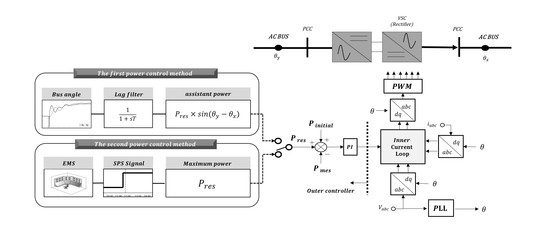
:This paper proposes two novel power control strategies to improve the angle stability of generators using a Back-to-Back (BTB) system-based voltage source converter (VSC). The proposed power control strategies have two communication systems: a bus angle monitoring system and a special protection system (SPS), respectively. The first power control strategy can emulate the behaviour of the ac transmission to improve the angle stability while supporting the ac voltage at the primary level of the control structure. The second power control scheme uses an SPS signal to contribute stability to the power system under severe contingencies involving the other generators. The results for the proposed control scheme were validated using the PSS/E software package with a sub-module written in the Python language, and the simple assistant power control with two communication systems is shown to improve the angle stability. In conclusion, BTB VSCs can contribute their power control strategies to ac grid in addition to offering several existing advantages, which makes them applicable for use in the commensurate protection of large ac grid.
1. Introduction
Back-to-Back system-based voltage source converters (BTB VSC) have been developed in numerous studies and are increasingly installed in ac grids [1,2]. The system is generally installed to improve the connection point of a renewable energy system, since the converter plays an important role in voltage swings during a contingency while decreasing the magnitude of the fault current in the ac grid. Another advantage of an embedded BTB system is that it increases the ac transmission transfer capacity by supporting the voltage and reduces the angle differences between each side of ac system. In the transient period, the system also contributes to voltage stability by applying ac voltage control strategy while sustaining their transfer power [3]. The ac voltage and the active power control are essential operational tasks in BTB VSCs to guarantee the proper stability of ac grid. However, the BTB VSCs generally sustain their fixed active power even though the ac grid has severe contingencies due to the fact that, unlike a Point-to-Point (PTP) system, frequency control with an embedded BTB system is useless in a large ac grid. Thus, novel transient power control schemes including two communication systems are newly introduced in this paper to expand the advantage of BTB VSCs. The proposed schemes contribute angle stability while also providing reactive power for voltage stability.
The BTB VSCs can further contribute transient stability using their advantage of flexible control. In fact, in the previous study, two kinds of transient power control methods were identified in the CIGRE (International Council on Large Electric Systems) conference, and one of them involves the use of WAMS (Wide Area Measurement Systems) by measuring the voltage and current from a GPS (Global Positioning System) system to prevent damping oscillation or an overload line problem [4]. The second method allows the power to increase its desired set point or to be automatically reduced as parallel ac transmission in the post-disturbance period. In detail, the active power reference of the BTB VSC is modified by the same amount as the parallel ac transmission line after the fault to resolve an overload situation. However, the first method has a major problem: the installation cost of entire grid monitoring system is too high. The second method lacks improvements in the transient response, and this type of control may not be practical given that the absence of the parallel ac transmission line restricts the use of power control. Furthermore, the overload problem is not eliminated at all positions according to the BTB system installation point.
The previous studies related to transient power control with BTB VSC has not been specifically illustrated, since the conservative operation with power control is general [3]. In the future, however, as the volatility of renewable energy sources increases, these Flexible AC transmission system (FACTS) will be required to be more flexible. To maximize the strengths of the BTB VSC, different form of control strategy is needed. Note that the ac voltage control is an ideal way to prevent the voltage instability in the embedded BTB VSC system, only power control is discussed in this paper. The first power control method using bus angle information acts like a frequency control in PTP HVDC, and it contributes the angle stability of several generators. It also finds a new convergence point immediately after a contingency such as ac transmission lines. The second power control strategy using a special protection system (SPS) signal could cause the tripped generator be reduced during the transient period, and it makes grid operation more flexible. The most important contribution of the proposed methods is that it can alleviate the first damping of the generators’ angle and prevent the rest from a potential loss of synchronism. To perform the analysis, in Section 2, the basic model of the VSCs is derived. In Section 3, two transient power control models are configured. Lastly, the angle stability evaluation using the proposed power control schemes with BTB VSCs is represented in Section 4. The angle spread analysis regarding first damping in PSS/E software is used to demonstrate the effectiveness of the proposed model.
2. VSC Model Configuration
2.1. VSC Configuration
Based on the Insulated Gate Bipolar Transistor (IGBT) and Pulse-Wide Modulation (PWM) skill, the VSC is capable of yielding a high active and reactive power input to the grid independently in a low grid voltage situation. Nowadays, Modular Multilevel Converter (MMC), using cascaded connection logic, is more attractive for application in the grid because of its unique features, e.g., the good sinusoidal waveform of its output voltage and low switching loss. Manufacturers have developed new generation of VSC based on MMC, and is has fast response speed, especially during the transient phase after disturbances such as voltage swing. In this paper, the MMC based BTB VSC system will be discussed.
In the BTB VSC system, the two converter stations are located at the same site, and the two ac systems are interconnected with either the same or a different frequency. The control of both active and reactive power is bi-directional and across the entire capability range. Within the capability curve, the VSC located in a weak ac system can support frequency and voltage drops and responses to several disturbances with fast dynamic control. To apply the bi-directional control of the converter, the ac current and voltage have to be transformed into a rotating direct-quadrature (d-q) frame. The rotating reference frame is aligned to the voltage phasor of the point of common coupling (PCC). Since the q-axis term of the voltage approaches zero, the converter enables the decoupled control of active and reactive power [5].
As we can be observed in Figure 1, the PCC voltage ( and converter voltage ( can be expressed with the resistance and inductance.
Using the d-q transform equation, (1) can be rewritten as:
in which is the angular frequency of the ac voltage at PCC and the well-known power equations in d-q reference frame with are expressed as
The (4) and (5) are used in the outer controller, and the active/reactive power is controlled by the decoupled d and q axis current. The above simple equations are one of the main reasons for using the d-q current control as the fastest inner control.
2.2. Inner Current Controller of VSC
The inner current controller which a faster response than the outer controllers includes Proportional Integral (PI) controllers and makes the voltage reference. The PI controllers are used to reduce the error in the d and q axis current control with ac grid parameters. A feedforward current is used to reduce the cross-coupling effect, and feedforward voltage ( is applied to compensate for the grid voltage disturbance as shown in Figure 2. Note that the system parameters depending on the feedback gain and time constant can cause problems in the inner fast control loops in a weak grid, the appropriate PI gains selection is needed. In this paper, however, selecting the optimal PI parameters is not a goal. The impact of the proposed model included in the upper hierarchical control structure is the only concern in this paper.
Figure 2 indicates that the control plants in both the d and q axis current control loops are identical. The PI controller allows one to track the dc reference command [6]. The closed-loop transfer function that includes the ac system dynamic as is represented as
in which the and are the total resistance and inductance between the PCC and the converter, respectively. Due to the system pole at , the magnitude and phase of the loop gain start to drop from a low frequency. The system pole is cancelled by the compensate zero, that is s = . The transfer function is rewritten by
in which is the time constant that impacts the system response and the bandwidth of the closed loop system. Depending on the system requirements, about 0.5–5 ms is taken as an appropriate range, and the parameters of PLL and PI controller have to be decided based on grid equivalent impedance in small signal stability domain.
2.3. Outer Current Controller of VSC
Unlike the inner control loops of a fast, first-order system, outer controller makes d-q current references achieve upper control object and ensures satisfactory response [7]. The d-axis current can control the active power and dc voltage; on the other hand, the q-axis manipulates the reactive power and ac voltage through inner current loops. In the power control, the q-axis current and d-axis voltage are considered as disturbances of the d-axis current control. The specific outer controller description with the proposed models are illustrated in the next Section.
3. Novel Two Power Control Models with Communication System
3.1. The First Power Control Model of BTB VSC
The process to obtain a first power control model with the bus monitoring system is explained in this section. The goal is to make BTB VSC act like an ac transmission when contingencies occur. It contributes to the improvement of transient stability, since it reacts like other ac transmission lines that find a new convergence point after a contingency. Therefore, the ac transmission characteristics have to be involved in the BTB VSC. In the ac grid, the transfer power is determined by each side of the angle difference that provides a clue to infer the condition of the ac system. The BTB VSCs equipped with each side of bus angle information can react differently depending on the ac grid condition. To apply the angle difference variation to an active power controller, below assumption is needed [8]:
The power transfer equation is illustrated as the sending end voltage , receiving end voltage and line impedance between two buses, in which is the angle difference between the sending and receiving ends. With the ac voltage control, the converter constantly controls the ac voltage as 1.0 pu, and the voltage variation is assumed to be zero. The impedance that determines the amount of power is a constant value between ac grid and BTB VSC system. Finally, in the VSC, the power variation occurs when the angle difference between connected two buses is detected.
In the first power control method, the angle information of each side of ac buses are transferred through a first order lag filter, and the information used in the assistant power controller to emulate the ac transmission power flow characteristics as shown in Figure 3. The filter is required for the measured signal to remove the initial overshoots, as well as any higher angle oscillations. The power reference changes when an angle variation is detected, and the reference is obtained as
in which is a delay constant from the control lag, output limiter, and communication system. The is initial dc power for the user-selected purpose in the steady-state condition. The can be set for various reasons by grid operators, including the maximum power-voltage margin, improved power transmission capability, minimum power transfer cost, etc. Note that the sin function has a range of −1 to 1, the assistant power reference is always smaller than remaining active power of the converter as . Thus, the determines the range of the angle stability improvement.
There are two purposes for a set value. First, the contingencies nearby the BTB VSC result in a high angle variation. This means that the assistant power reference could have large fluctuations in a small power system [9]. This easily impacts the system stability in which grid inertia is low. Second, the unlimited power reference could impact the system margin, leading to an unstable eigenvalue mode of active power controller. Therefore, setting the is reasonable.
In detail, for example, when the fault occurs right next to the side of the BTB, the arbitrary bus angle at the side is immediately increased, since nearby generators increase their rotor speed to supply active power. What we want to see is the first damping of the bus angle in a sequence of a contingency. From Figure 3, the angle variation of the side more sensitively increases rather than the opposite side of . From (9), the bus angle makes terms negative in transient time, and the becomes negative as well. The total power output () is decreased to deliver more power to the side. On the other hand, when the fault occurs right next to the side of the BTB, bus angle at the side is more increased than the other side in transient time. It makes terms positive, and the total output power going to side is increased. In conclusion, the bus angle information reflects the ac grid condition directly after the contingency, and more power flows from the converter to the ac grid with the first power control strategy can reduce the required decelerating energy.
The operation point of the active power is consistently changed due to varying angle differences such as ac transmission line; therefore, the grid operators should accurately determine the reserve active power as . The reason for using reserve power and not using initial power ( for the proposed power control is that it can easily make the reverse direction power flow from the angle measuring system. This involves a high variation in power change, and it can worsen the ac grid condition in some cases. Also, another object of the first method is to use the remaining converter capacity to increase the converter utilization. Thus, the first power control method contribution to the stability of the ac grid is naturally constrained by a limiter.
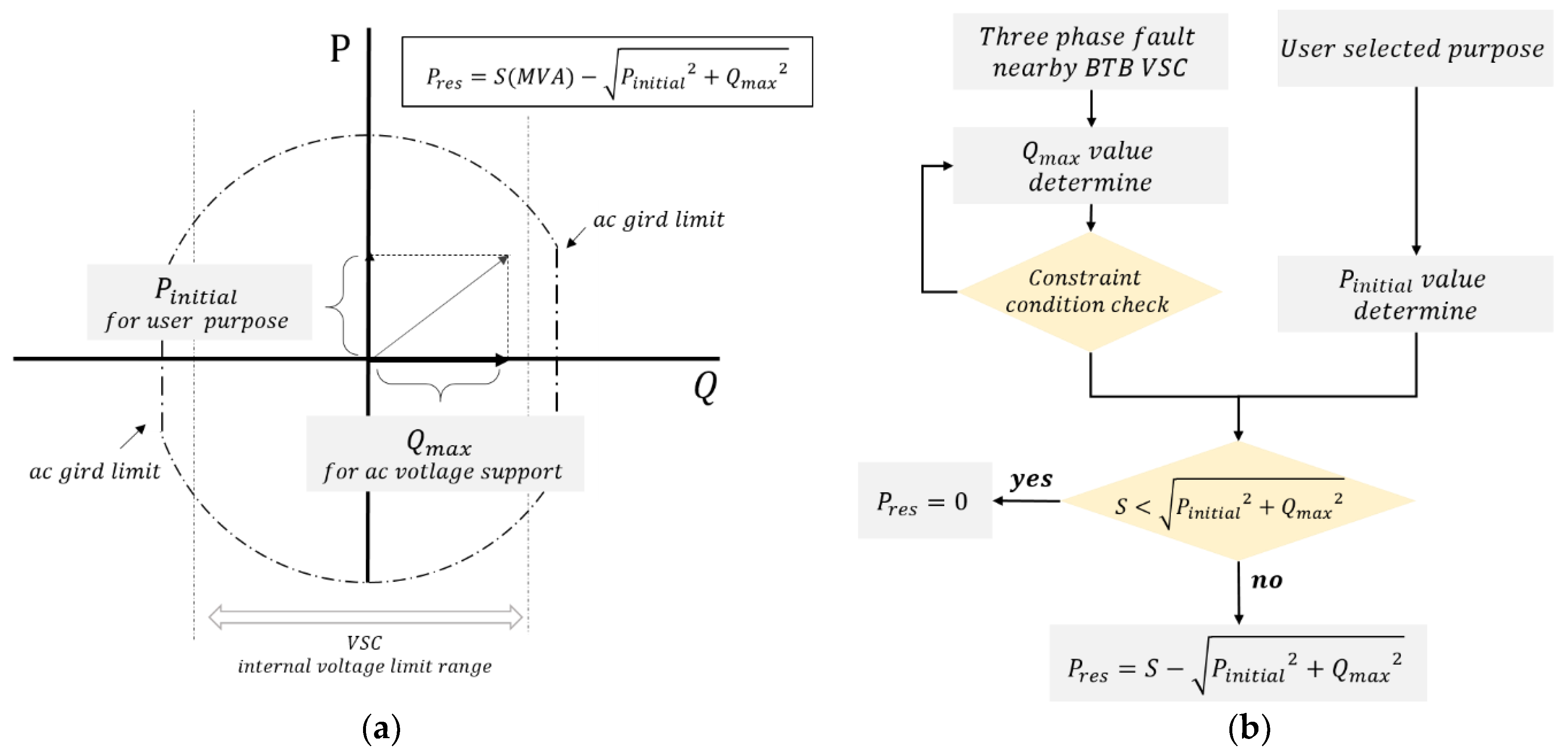
The specific determination process of reserve active power is illustrated hereafter. The is calculated by the converter rating (S), required reactive power ( from a severe contingency, and the initial active power (.
Since the ac voltage control of the embedded BTB VSC has the highest priority in the transient time, sufficient reserve capacity of the reactive power such as is required. However, the reactive power injecting or absorbing the ac grid can be limited by key parameters such as the ac grid voltage, converter voltage, and ac grid equivalent impedance. The maximum reactive power the converter can absorb or inject to the ac grid is limited by the two well-known equations below [10]. The reactive power is constrained by the (11) as the “critical frontier” is the relation between the transmitted active power and reactive power. Beyond the critical frontier area, the ac grid voltage becomes unstable and collapses.
in which
is the VSC reactive power;
is the ac grid voltage;
is the reactance between the VSC and the ac grid
Other equations such as (12) represent the capability of the VSC to inject the reactive power into the ac system. (12) formed circular is moved by the ac grid voltage and equivalent impedance.
in which
is the apparent power at the ac system node;
is the converter side voltage;
The allowable reactive power range is firstly calculated to determine the range of . If the reactive power is not limited by the ac grid condition, the is chosen based on the required amount when the three-phase fault occurs near the BTB VSC system. If the reactive power consumption to maintain the voltage of the weak ac grid is large, the converter following the tendency of the ac transmission characteristic is naturally limited. The detailed determination process is illustrated below in Figure 4.
3.2. The Second Power Control Model of BTB VSC
Each country, whether it has a different Special Protection System (SPS), as the generators tripping schemes are generally called, commonly commands specific generators to be tripped to balance the grid power. This process is generally adopted by grid operators, and to prevent the fault spread, the SPS signal that commands each generator to be tripped is activated. Under an N-2 contingency, as the level of fault increases, more generator rejection has to be applied to sustain the grid stability. The common protocol of SPS is performed according to time domain simulation with major contingencies, and the stability margin is determined by the index of acceleration and the decelerating energy [11,12].
With the second power control strategy, the flexible operation of the generator tripping scheme can be achieved without significant decelerating energy as the generators trip. The BTB VSCs surely contributes to the stability of the ac grid using a simple converter control strategy that transfers the maximum power reserve instantly to the fault area. Note that the more VSCs equipped with a proposed power control scheme the flexible tripping schemes on the generators will be possible for grid operators.
Figure 5 represents the diagram of the second power control scheme. If the SPS signal is activated, the power reference with the second power control scheme is represented by
in which is the delay time when the BTB VSC receives the SPS signal, and it is set by 5 cycles after the fault in this paper. The activating time is naturally faster than the generator tripping scheme as with 9 cycles, since mechanical switch is not included. The F coordinated by the grid operators only impacts the direction of the active power reserve based on the fault position, and the S1 and S2 are the switch to separate the first power control and the second power control method. The initial value of S2 is zero for the first method.
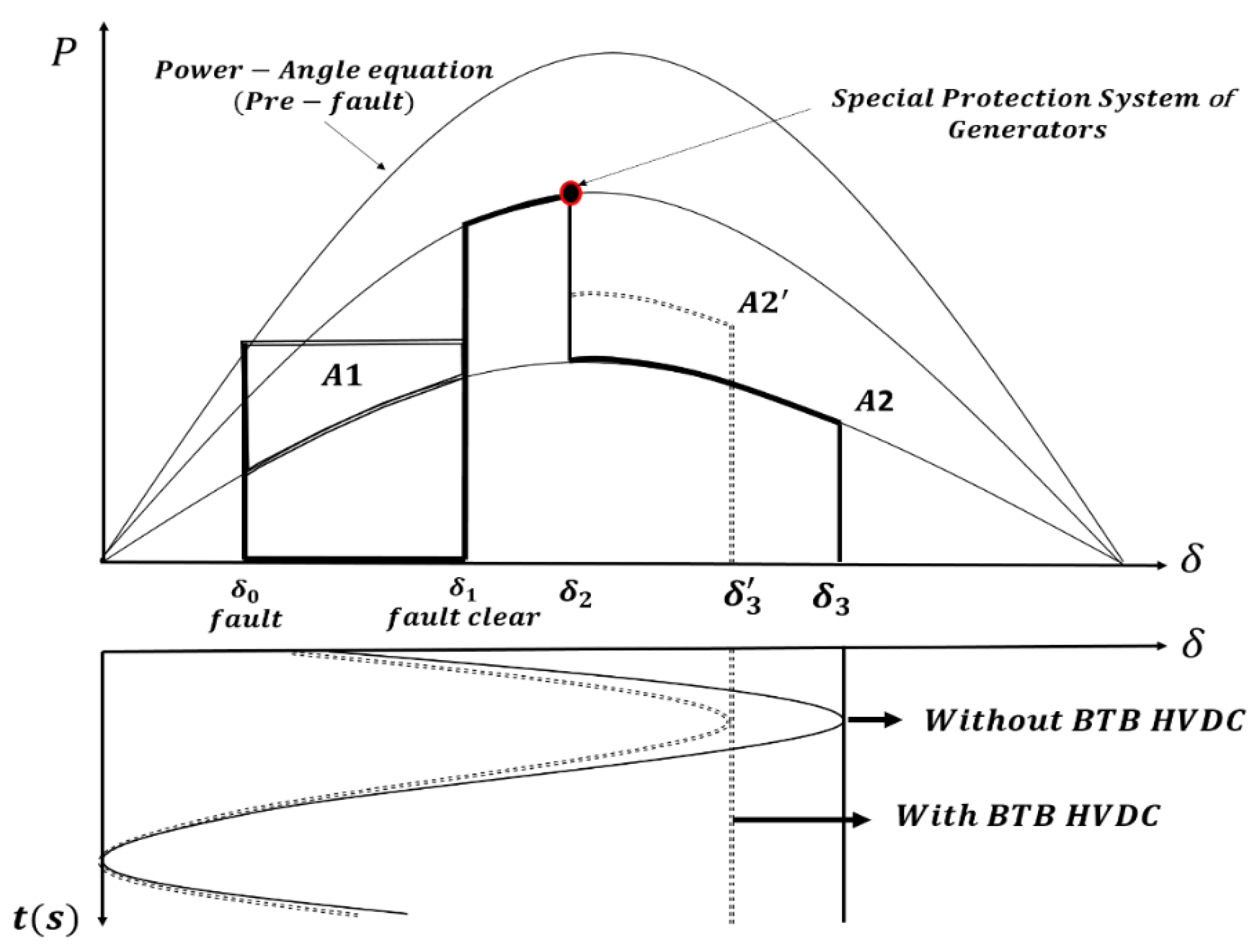
To verify the effectiveness of the second power control method, the Equal Area Criterion (EEAC) concept is introduced. From the well-established EEAC [11,12], the accelerating area is defined as , and the decelerating area as . To configure the stable system, the size between and has to be equal. The main cause of this improvement is that the proposed strategy can increase the height of the area during contingency. Figure 6 represents the power-angle curve and the decelerating area with and without the second power control strategy.
From [11,12], the rotor angle ( increases by increasing the mechanical output or by reducing the electrical output as in (14):
in which E is an internal voltage of the generator, and and are the reactance of an equivalent transformer reactance and reactance of the transmission lines, respectively. The relation between and with a generation tripping scheme can be represented by (16), and the common protocols of calculating the area with the second power control scheme can be written as
in which is the start time when the second power controller impacts the VSCs. If the BTB VSCs receive the SPS signal where a severe contingency occurs in the ac system, the corresponding , which is the maximum reserve power, is used. With the proposed scheme, the loss of mechanical output generated by the tripping scheme is naturally smaller than (17). (18) verifies that the first damping angle of the equivalent generators could be reduced further than the non-applied proposed operation scheme. The main one prevents the rest from a potential loss of synchronisms where the proposed scheme is applied. Eventually, the second control strategy can reduce the number of generator units ordered by SPS.
4. Simulation Study with Proposed Power Control Models
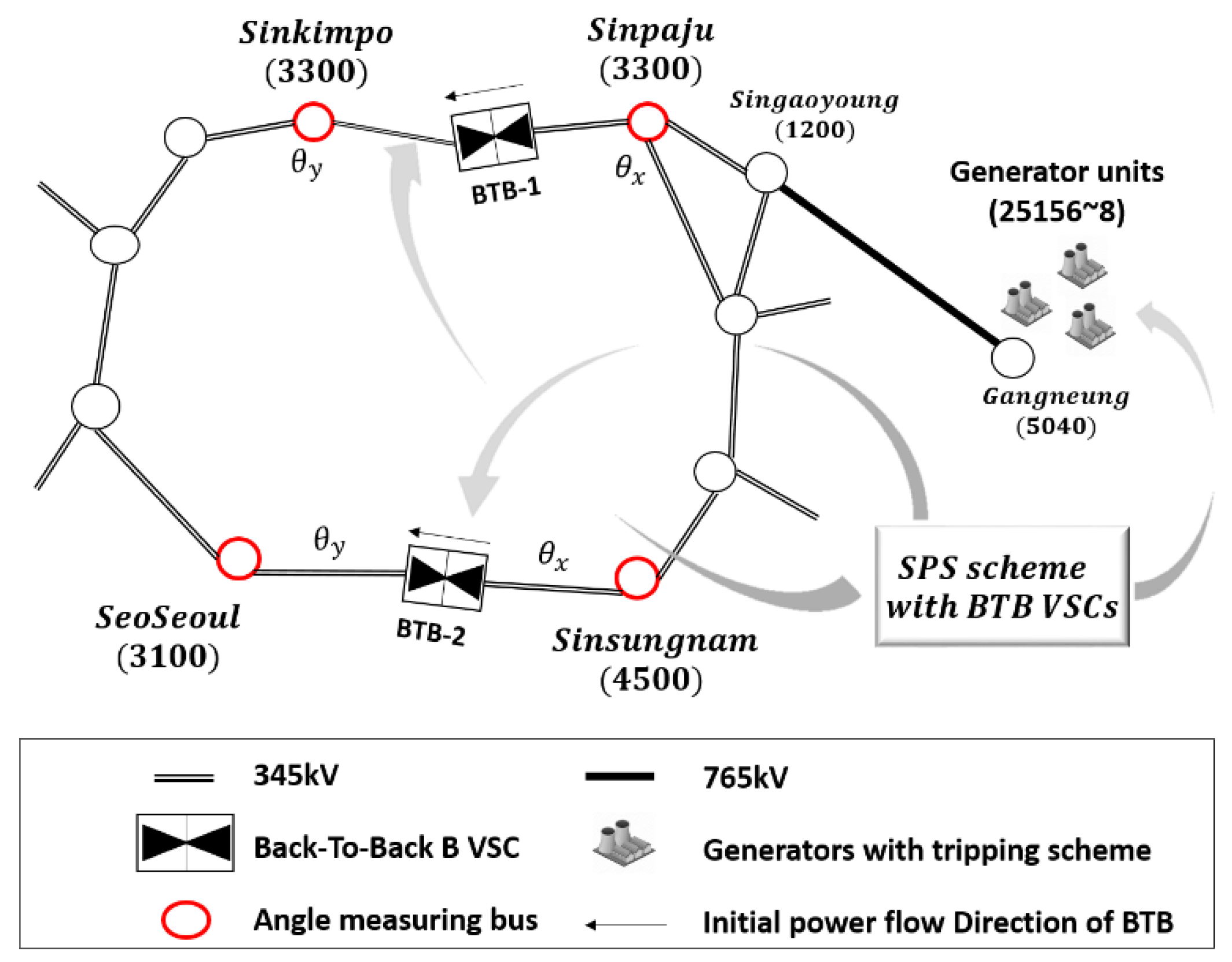
To demonstrate the effect of the proposed models, two BTB VSCs are employed to evaluate the performance of the power control structure and its impact on the behaviour of the proposed scheme under several contingencies. A simulation was carried out on the Korea power system, for which a diagram and candidate places for BTB VSCs are presented in Figure 7. Two places as ‘Sinkimpo-Sinpaju’ and ‘SeoSeoul-Sinsungnam’ have several instability network problems, including a high fault current, high angle difference, voltage instability, and overload. In order to overcome the mentioned shortcomings, KEPCO (Korea Electric Power Corporation) is considering BTB VSC systems. The detailed system specification is represented in Table 1.
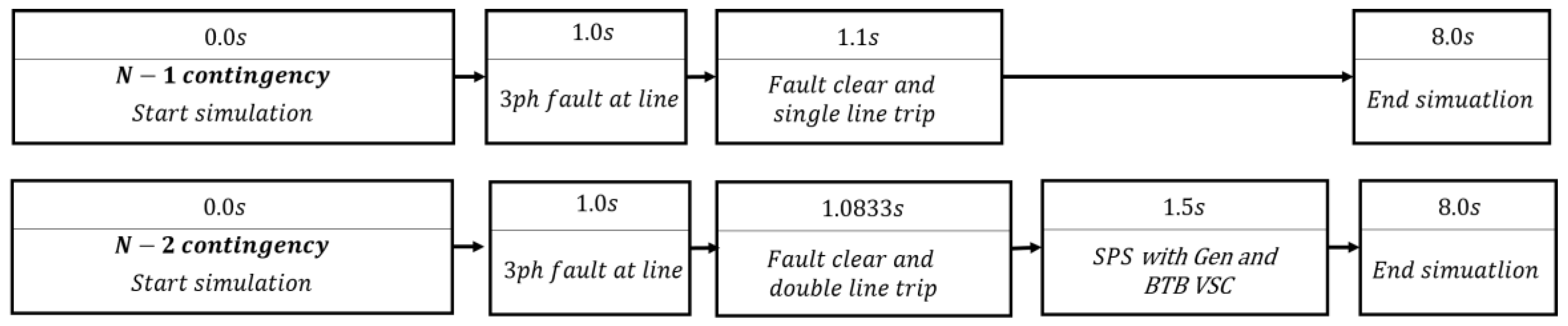
The result is performed against the PSS/E (Power Transmission System Planning Software) with a sub-module written in the Python language. The limiter and assistant power controller that have a constant time delay from communication system were also setup on sub-module program. The initial dc power is selected to secure the maximum power-voltage margin in the ac grid, and the contingency scenarios are shown in Figure 8.
The simulation setup of the BTB VSCs is at two different places, one for the N-1 contingency at the upper place using the first power control method, and one in both places to apply the N-2 contingency with the second power control strategy. In the N-2 contingency scenario, the SPS signal is transmitted to both generators and BTB VSCs. To verify the difference between the value of the which is included in different limiters as “limiter-1” and “limiter-2”; the devices were stepped with the purpose of observing the contribution to the ac grid, as shown in Figure 9.
The limiter-1 has a small reserve capacity due to a large or value. On the other hand, the limiter-2 allows a large reserve capacity with a small or value. With the limiter-2, the BTB VSC transfers substantial active power to the fault area based on the angle difference. The reactive restrictions of the two BTB points were all guaranteed through (11) and (12).
4.1. N-1 Contingency with the First Power Control Method of BTB VSC
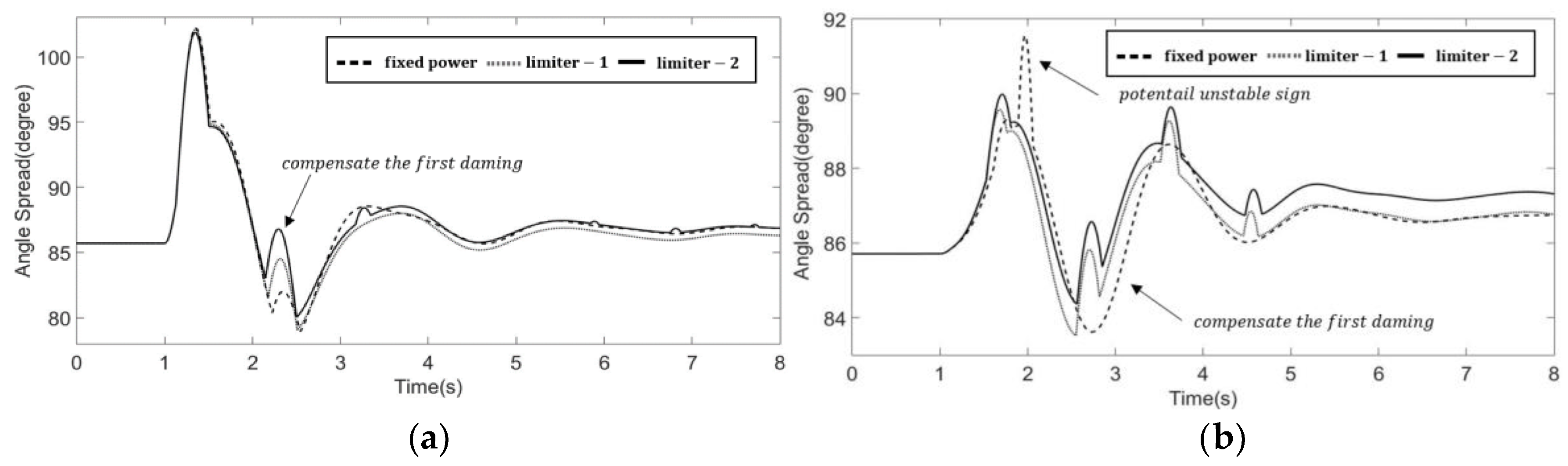
(1) Scenario 1—A loss of 345 kV mono-pole scenario near the Sinsungnam (4500) bus is applied to simulate the N-1 contingency, as shown in Figure 10a and Figure 11a. A rise in the angel variation in the fault area implies a higher command of the active power in the BTB VSC. Therefore, the first damping is mitigated at , as shown in Figure 10a. This is because the converter reduces its power to supply more active power into the fault area that is at the side, as shown in Figure 11a.
(2) Scenario 2—Contrary to the first scenario, a loss of a 345kV mono-pole near the SeoSeoul (3100) bus is discussed in Figure 10b and Figure 11b. The fixed power control, illustrated in Figure 10b, has a potentially unstable condition at due to the first damping. The stabilization of this situation requires several types of SPS to balance the power. For a VSC under the first control scheme, the first angle damping can be mitigated, leading to a stable system. Again, given the different limiter, the bold line as limiter-2 has a large capacity for active power compared to limiter-1. The value of increased, and the contribution to the angle stability increased. The findings from Figure 10 and Figure 11 indicate that a trade-off must be made between improvements in the angle stability and the economics related to the convert sizing. Also, the power control in BTB VSC is demonstrated to contribute to the ac grid, besides having other advantages.
In addition to the above cases and for the sake of clarity, the result of three more contingencies using the first power control model is illustrated in Table 2. Note that each contingency made a different angle variation, the effects of the applied proposed scheme are all different.
4.2. N-2 Contingency with the First Power Control Method of BTB VSC
In Korean power systems, to satisfy the grid reliability, the SPS was triggered by the generator tripping scheme. To verify the second power control with the SPS signal, a simulation with a loss of a 765 kV double-pole is applied in this section. During the contingency, the three generators that are represented by Table 3 must be tripped to maintain the power balance.
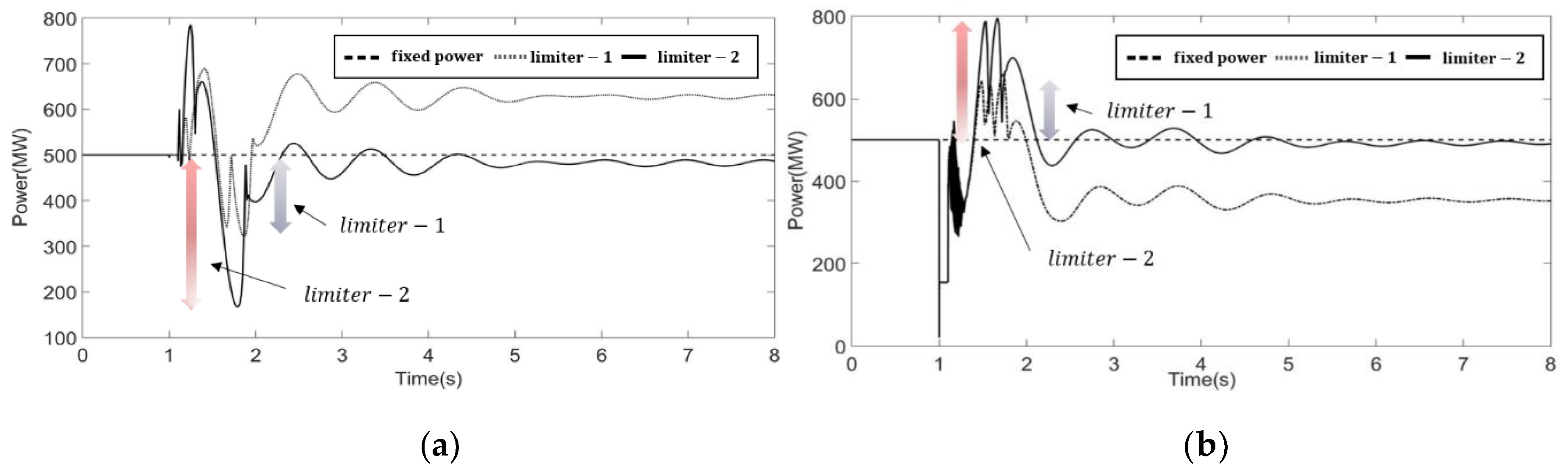
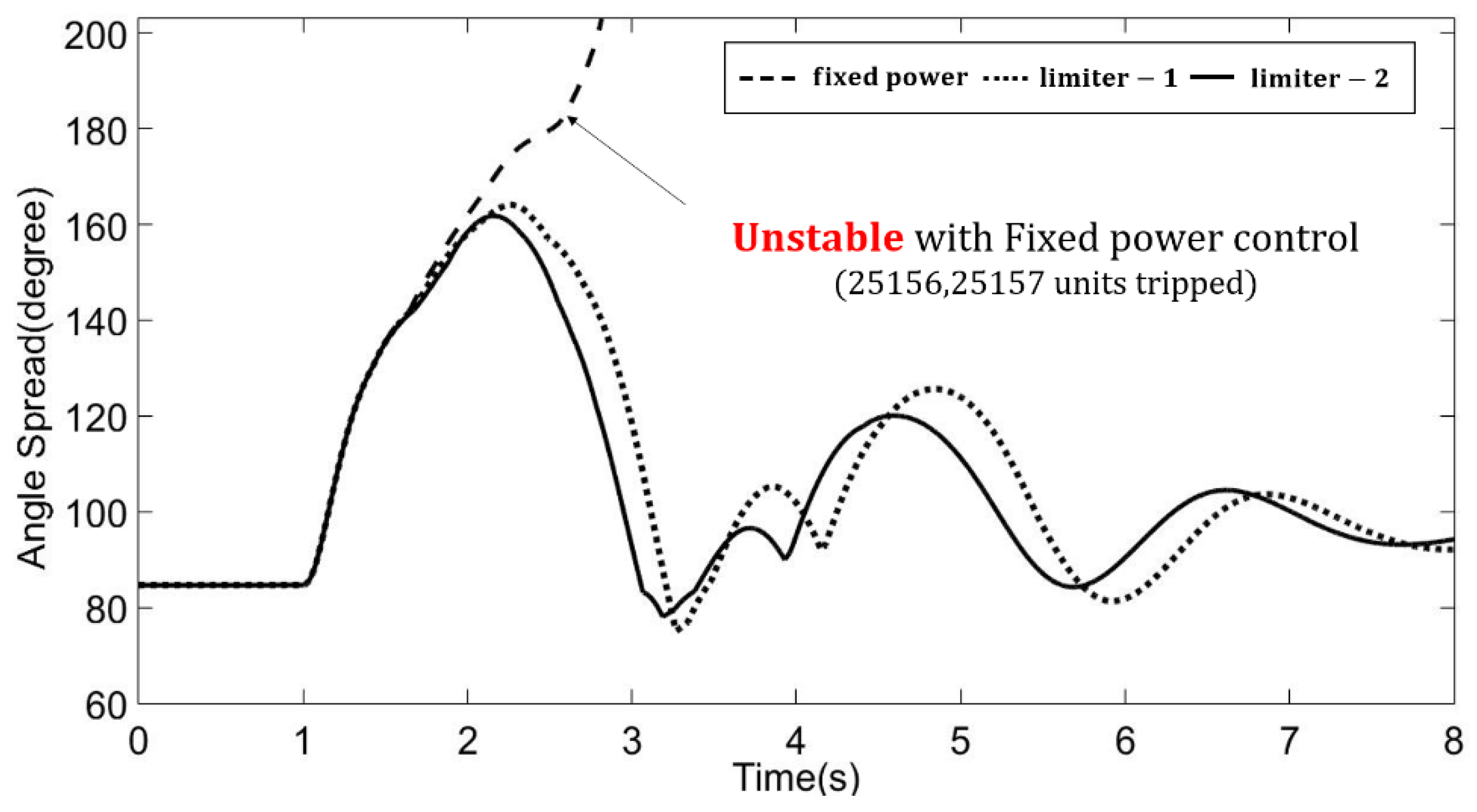
Unlike the present situation in Korean grid operation systems, the two BTB VSCs also receive the signal of the SPS with other generators only in this scenario. The second power control model sets their maximum power in the BTB VSC according to (13). Figure 12 represents the active power of two BTB VSCs according to two different limiters. The fixed power control with BTB VSCs makes the power system unstable with a two-generator tripping scheme, as in Figure 13. However, from the angle stability analysis with a time domain simulation, this result demonstrates that using the second power control scheme with BTB VSCs could reduce the tripped generator from three to two as shown in Table 4, and the stability margin is adequately acquired. Through this simulation, it was demonstrated that the BTB VSCs with SPS signal can be applied to a commensurate protection system in a large interconnected system.
5. Discussion
In the complex ac grid, the grid operators find it hard to predict when the contingencies will occur. Furthermore, changing the control mode depending on each fault scenario is annoying. To resolve such problems, BTB VSCs with two power control strategies are proposed in this paper, and their capability for angle stability was sufficiently demonstrated in an unpredicted contingency. The proposed control schemes are also able to act like a form of SPS, and depending on the contingency scenario, the effectiveness of the proposed models can be more escalated.
6. Conclusions
The BTB VSC is commonly installed to increase the voltage stability of a weak ac grid or the interconnection points of renewable systems. Also, it plays an apparent role in reducing the fault current magnitude and increasing the transfer capability in the ac transmission. In this paper, however, to maximize the advantages of embedded BTB VSCs, new power control strategies are proposed to improve the angle stability. The novel power control models are demonstrated to easily contribute angle stability in the ac grid with a simple assistant controller while reducing the number of tripped generator units.
Author Contributions
The main control schemes were proposed by S.S and G.J.; The experiment results were collected and analyzed by S.H, B.K and S.C.
Funding
This research received no external funding
Acknowledgments
This work was supported under the framework of the international cooperation program managed by the National Research Foundation of Korea (No. 2017K1A4A3013579) and the Human Resources Program in Energy Technology of the Korea Institute of Energy Technology Evaluation and Planning (KETEP).
Conflicts of Interest
The authors declare no conflict of interest.
References
- Kidd, D.; Mehraban, B.; Ekehov, B.; Ulleryd, J.; Edris, A. Eagle pass back to back VSC installation and operation. In Proceedings of the Power Engineering Society General Meeting, Portland, OR, USA, 5–9 August 2018; pp. 1829–1833. [Google Scholar]
- Sankar, S.; Rector, J.; Fairly, P.; Marz, M.; Copp, K.; Manty, A.; Irwin, G. ATC’s Mackinac Back-to-Back HVDC Project: Planning and Operation Considerations for Michigan’s Eastern Upper and Northern Lower Peninsulas. In CIGRE US National Committee 2013 Grid of the Future Symposium; ISO New England Inc.: Holyoke, MA, USA, 2013. [Google Scholar]
- Pan, J.; Nuqui, R.; Srivastava, K.; Jonsson, T.; Holmberg, P.; Hafner, Y.-J. AC grid with embedded VSC-HVDC for secure and efficient power delivery. In Proceedings of the Energy 2030 Conference, Atlanta, GA, USA, 17–18 November 2008; pp. 1–6. [Google Scholar]
- Kim, M.-Y.; Song, Y.-U. The Analysis of Active Power Control Requirements in the Selected Grid Codes for Wind Farm. J. Electr. Eng. Technol. 2015, 10, 1408–1414. [Google Scholar] [CrossRef] [Green Version]
- Fang, X.; Chow, J.H. BTB DC link modeling, control, and application in the segmentation of AC interconnections. In Proceedings of the Power & Energy Society General Meeting, Calgary, AB, Canada, 26–30 July 2009; pp. 1–7. [Google Scholar]
- Yazdani, A.; Iravani, R. Voltage-Sourced Converters in Power Systems: Modeling, Control, and Applications; John Wiley & Sons: Hoboken, NJ, USA, 2010. [Google Scholar]
- Rouzbehi, K.; Miranian, A.; Candela, J.I.; Luna, A.; Rodriguez, P. A generalized voltage droop strategy for control of multiterminal DC grids. IEEE Trans. Ind. Appl. 2015, 51, 607–618. [Google Scholar] [CrossRef]
- Song, S.; Kim, J.; Lee, J.; Jang, G. AC Transmission Emulation Control Strategies for the BTB VSC HVDC System in the Metropolitan Area of Seoul. Energies 2017, 10, 1143. [Google Scholar] [CrossRef]
- Konishi, H.; Takahashi, C.; Kishibe, H.; Sato, H. A consideration of stable operating power limits in VSC-HVDC systems. In Proceedings of the Seventh International Conference on AC and DC Transmission, London, UK, 28–30 November 2001; pp. 102–106. [Google Scholar]
- Pinto, R.T. Multi-Terminal DC Networks: System Integration, Dynamics and Control. Ph.D. Thesis, Delft University of Technology, Delft, The Netherlands, 4 March 2014. [Google Scholar]
- Xue, Y.; Wehenkel, L.; Belhomme, R.; Rousseaux, P.; Pavella, M.; Euxibie, E.; Heilbronn, B.; Lesigne, J.-F. Extended equal area criterion revisited (EHV power systems). IEEE Trans. Power Syst. 1992, 7, 1012–1022. [Google Scholar] [CrossRef]
- Xue, Y.; Van Custem, T.; Ribbens-Pavella, M. Extended equal area criterion justifications, generalizations, applications. IEEE Trans. Power Syst. 1989, 4, 44–52. [Google Scholar] [CrossRef]
Figure 1.
Voltage Source Converter single diagram.
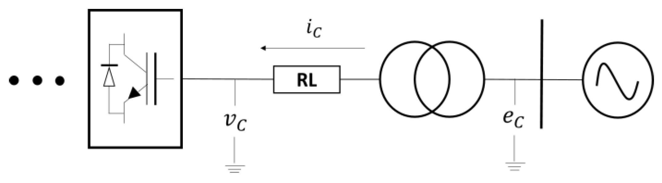
Figure 2.
Inner current control loop.
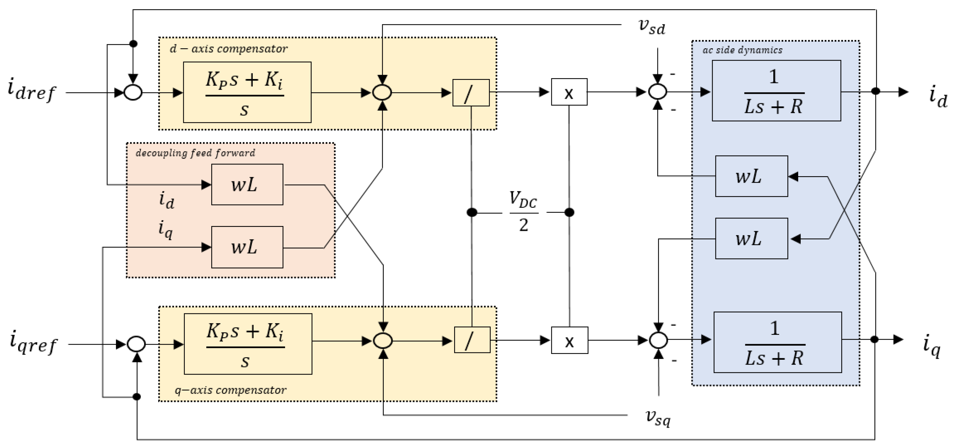
Figure 3.
The first power control model structure of BTB.
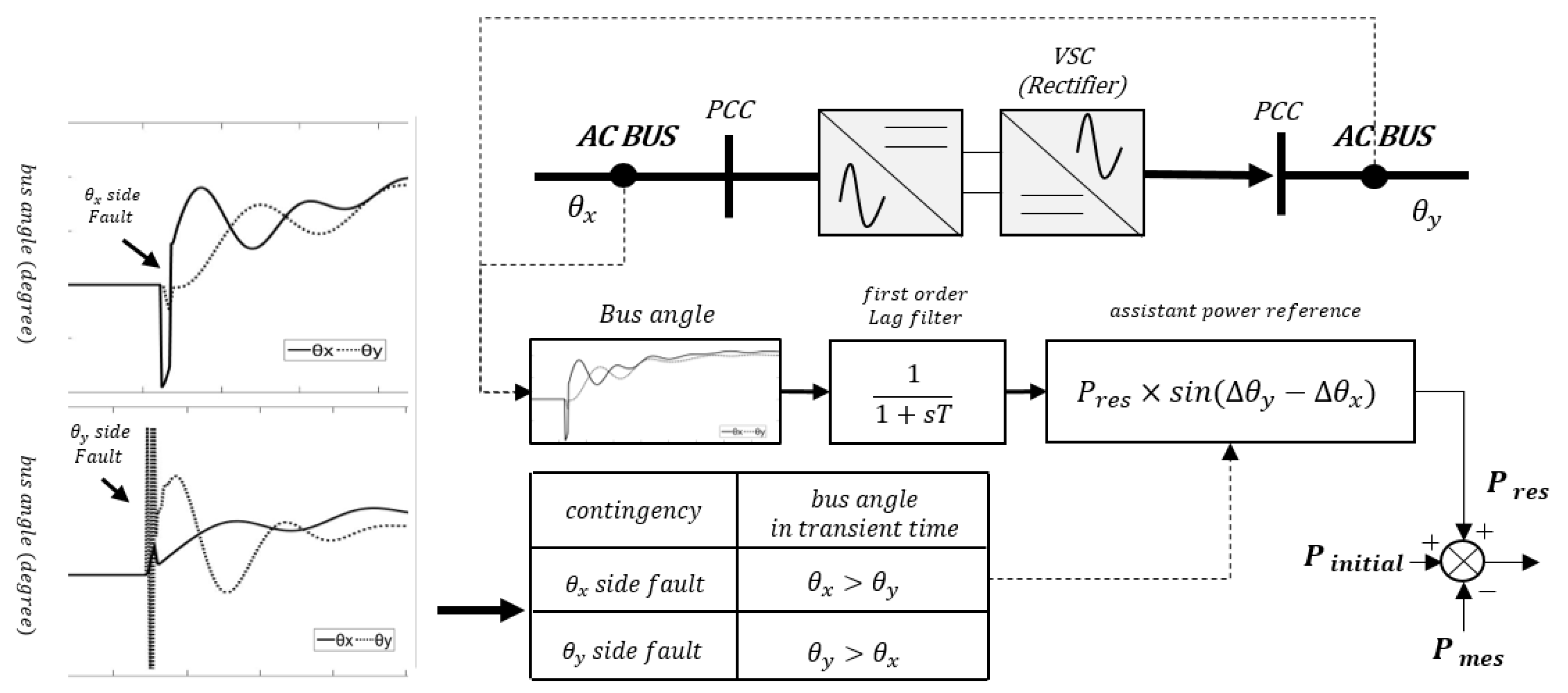
Figure 4.
(a) Capability curve of BTB VSC and (b) determination process of value.

Figure 5.
The second power control model of BTB VSC.
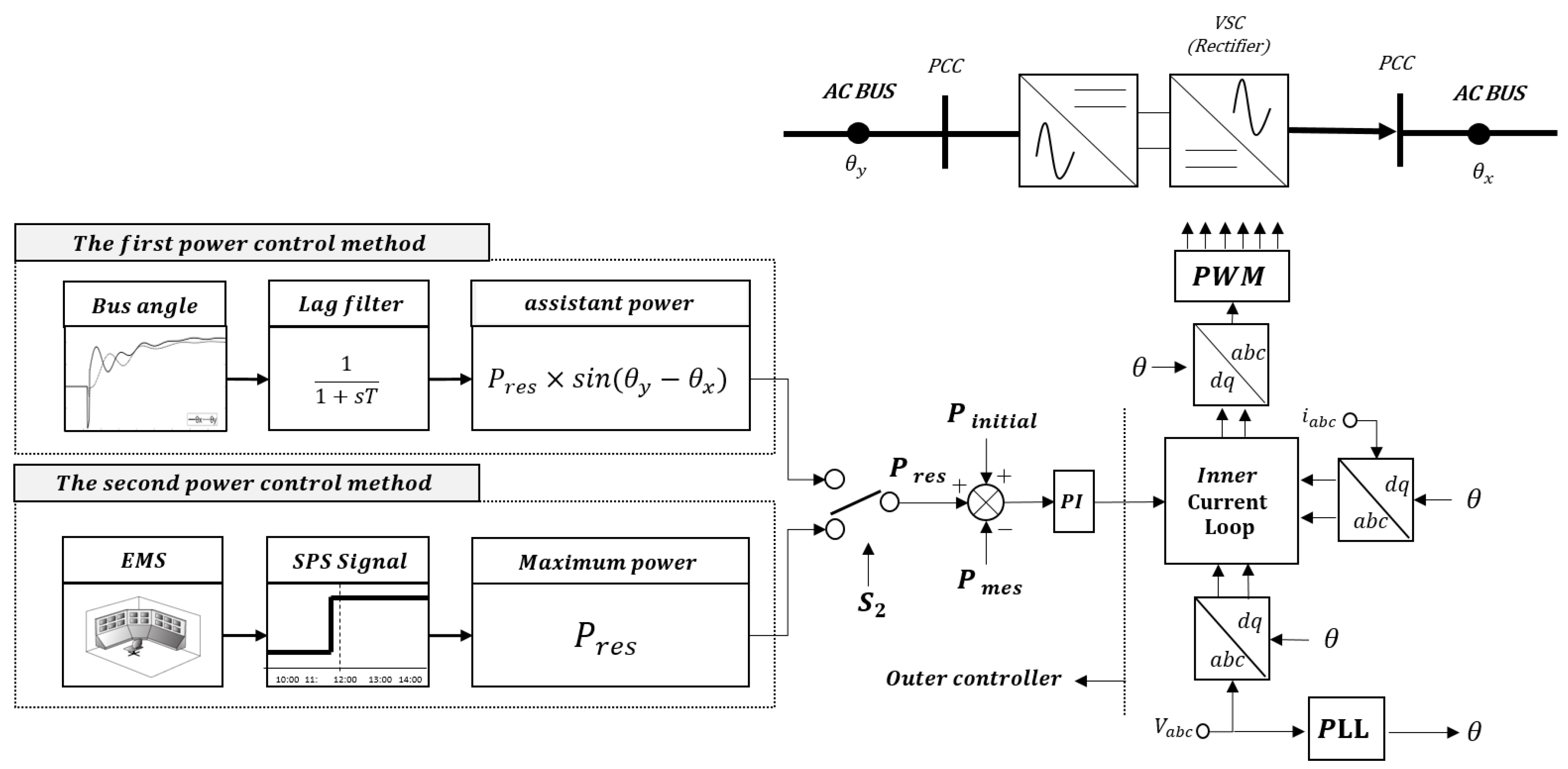
Figure 6.
Equal Area Criterion with the second power control strategy.

Figure 7.
Simulation environment in Korea power system.

Figure 8.
Contingency scenarios.

Figure 9.
The limiter configuration in simulation study.
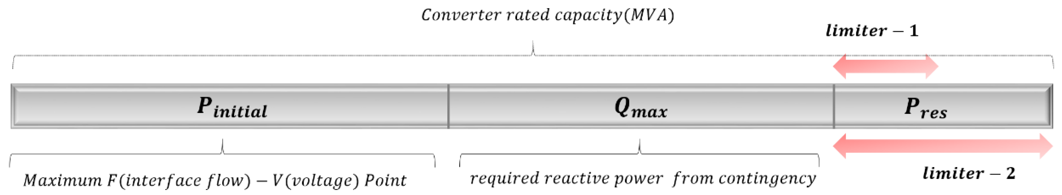
Figure 10.
Angle spread of ac grid, (a) left side fault (, and (b) right side fault (.

Figure 11.
Active power of BTB VSCs, (a) left side fault (, and (b) right side fault (.

Figure 12.
Active power of BTB VSCs with different .
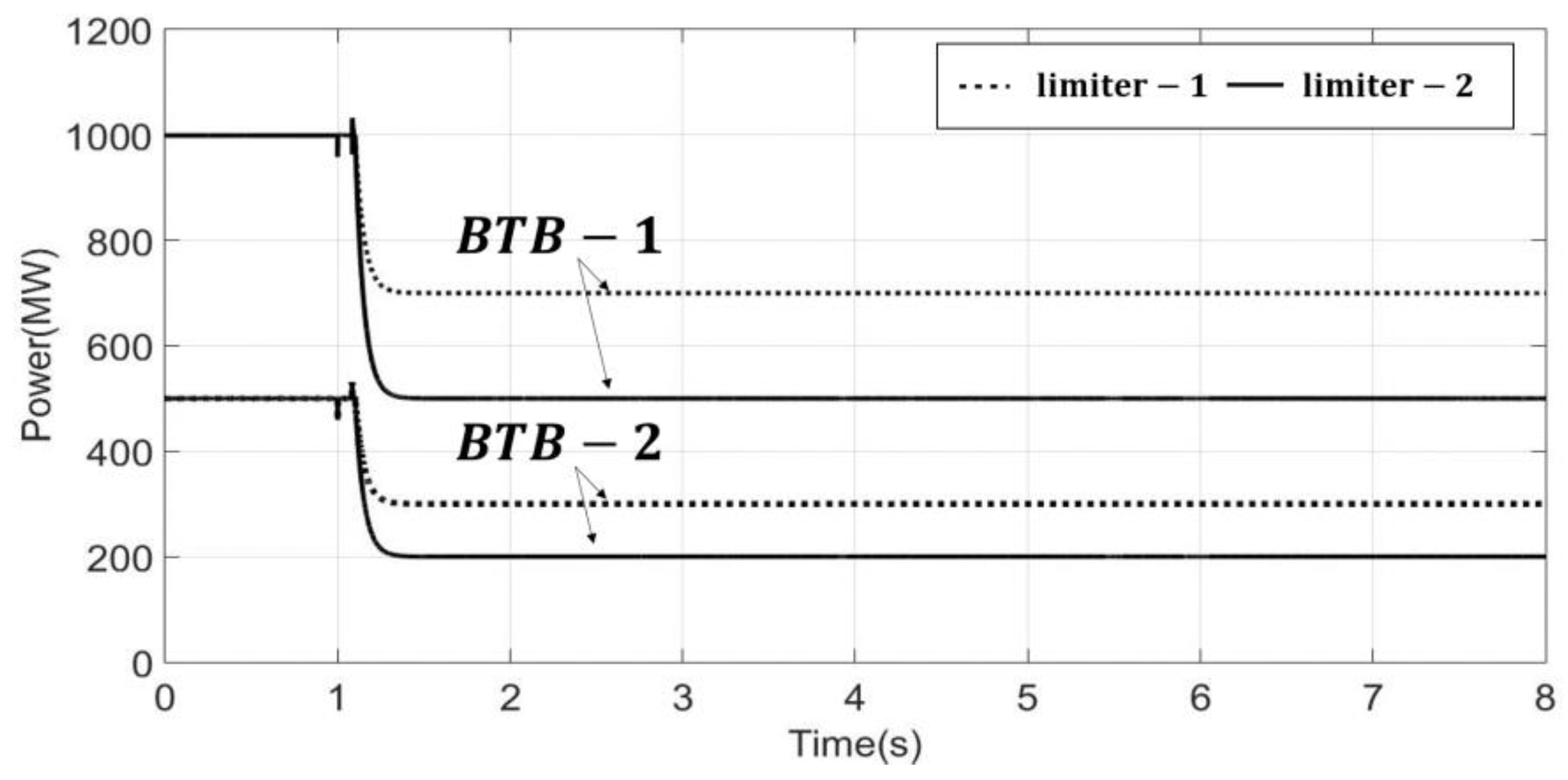
Figure 13.
Angle spread result in an N-2 Contingency.


Table 1.
System parameter of BTB VSC.
| Item | BTB-1 | BTB-2 |
|---|---|---|
| Installation point | 3300–1300 | 3100–4500 |
| Rated converter | 1500 MVA | 1000 MVA |
| Equivalent impedance at BTB point | 6.638 + 11.713j | 1.216 + j5.531 |
| AC Terminal voltage | 354 kV | |
| DC link voltage | 400 kV | |
| System frequency | 60 Hz | |
| Active power controller gain | 0.8 rad/s | 0.5 rad/s |
| Active power controller time constant | 0.02 rad/s | 0.01 rad/s |
| Inner current controller gain | 1.2 rad/s | 0.8 rad/s |
| Inner current controller time constant | 0.1 rad/s | 0.2 rad/s |
Table 2.
The effect of the first power control scheme in other contingencies.
| Contingency Num | Fault Location | Improvement Range of First Angle Damping |
|---|---|---|
| 1 | 1550–1400 | 6° |
| 2 | 1350–1301 | 2.6° |
| 3 | 1400–1800 | 4.5° |
Table 3.
The generators’ status-receiving SPS signal.
| Gen Num | Gen Name | Gen Capacity |
|---|---|---|
| 25156 | Hanul #6 | 1 GW |
| 25157 | Hanul #7 | 1.5 GW |
| 25158 | Hanul #8 | 1.5 GW |
Table 4.
Reduced tripped generator with the second power control scheme in N-2 contingency.
| Without the Second Power Control | With the Second Power Control | |
|---|---|---|
| Tripped Generators | 25156; 25157; 25158 | 25156; 25157 |
© 2018 by the authors. Licensee MDPI, Basel, Switzerland. This article is an open access article distributed under the terms and conditions of the Creative Commons Attribution (CC BY) license (http://creativecommons.org/licenses/by/4.0/).
Share and Cite
MDPI and ACS Style
Song, S.; Hwang, S.; Ko, B.; Cha, S.; Jang, G. Novel Transient Power Control Schemes for BTB VSCs to Improve Angle Stability. Appl. Sci. 2018, 8, 1350. https://doi.org/10.3390/app8081350
AMA Style
Song S, Hwang S, Ko B, Cha S, Jang G. Novel Transient Power Control Schemes for BTB VSCs to Improve Angle Stability. Applied Sciences. 2018; 8(8):1350. https://doi.org/10.3390/app8081350
Chicago/Turabian StyleSong, Sungyoon, Sungchul Hwang, Baekkyeong Ko, Seungtae Cha, and Gilsoo Jang. 2018. "Novel Transient Power Control Schemes for BTB VSCs to Improve Angle Stability" Applied Sciences 8, no. 8: 1350. https://doi.org/10.3390/app8081350
Note that from the first issue of 2016, this journal uses article numbers instead of page numbers. See further details here.