1. Introduction
In 1995, Jacobson et al. pointed out that an ensemble of photons (under certain conditions) could be treated as in a Bose condensate and has a de Broglie wavelength given by
, where
and
N are the wavelength and average number of photons, respectively [
1]. The wavelength of those photons is determined by the “internal structure” of them, i.e., the de Broglie wavelength of those photons, or if it has a de Broglie wavelength at all, it is determined by the situation of its internal binding. The photonic de Broglie wavelength of multiphoton states can be measured by using an interferometer with an “effective beam splitter” that does not split multiphoton states into different parts. Interestingly, the experimental measurements of the photonic de Broglie wavelength of biphotons was actually earlier than the theory. People measured the photonic de Broglie wavelength of biphotons in a series of experiments with SPDC (spontaneous parametric down conversion) light [
2,
3,
4]. Later on, the de Broglie wavelength of biphotons was measured intently by using a similar Young’s interferometer setup and a basic Mach–Zehnder interferometer [
5,
6]. The shorter wavelength of the photonic de Broglie wavelength (compared to the constituent photons of biphotons/multiphotons states) was proposed to be used in “quantum lithography”, optical imaging with multiphoton states (NOON states for example) to beat the classical diffraction limit [
7,
8]. In 2001, D’Angelo et al. demonstrated quantum lithography in a proof-of-principle experiment using degenerate SPDC light [
9].
The major advantage of quantum lithography is the resolution enhancement. With light (in the NOON state), the wavelength of which is
, the resolution of quantum lithography will be enhanced
N-times, as if the light with wavelength
were used for classical lithography. Previously, the multiphotons used in quantum lithography experiments were usually composed of photons with the same wavelength (except in [
4] in which the non-degenerate biphotons were studied in a Mach–Zehnder interferometer). In this paper, non-degenerate quantum lithography is reported. We design a set of experiments to study the spatial interference and diffraction of non-degenerate biphotons. The biphotons are composed of “two photons” with different wavelengths, and the binding between the two photons is established through an SPDC process in a nonlinear crystal. Through experimental measurements, we find that the photonic de Broglie wave is well defined in spite of the wavelength difference between the daughter photons, and their de Broglie wavelength is neither the wavelength of the signal, nor the idler photon. We show that the wavelength of the non-degenerate biphoton is determined by the sum of the momenta of signal and idler photons due to the internal binding. The non-degenerate ghost interference/diffraction is also observed.
2. Experiments
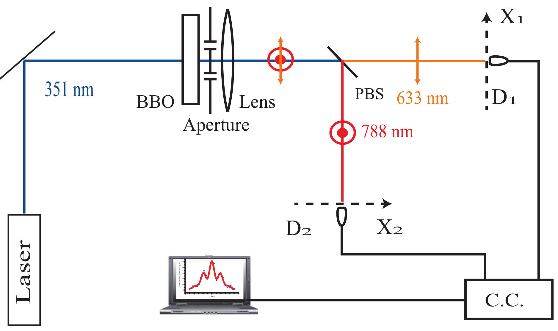
The experimental setup is shown in
Figure 1. The laser beam (351 nm) pumps a 3-mm thin BBO crystal to generate non-degenerate entangled photon pairs through the SPDC process. The wavelengths of the signal photons and idler photons are 633 nm and 788 nm, respectively. The polarizations of signal and idler photons are horizontal and vertical, respectively. Furthermore, they are designed to emit in the same direction of the pump. In other words, the SPDC process generates Type II, collinear and non-degenerate entangled photon pairs. Right after the crystal, there is the object (a single slit or a double slit). For the double slit used in experiments, the width of each slit is
mm and the distance between the center of each slit is
mm. For the single slit used in experiments, the width is
mm. The objects are put as close as possible to the crystal to rule out the possibility that a pair of entangled photons passes through different slits when a double slit is used as the object. There is a convex lens with a 1000-mm focal length right after the object. After the lens, there is a polarized beam splitter (PBS), which is 450 mm away from the lens, to split the entangled photons beam into two. All signal photons (633 nm, horizontal polarized), are transmitted and all idler photons (788 nm, vertical polarized) are reflected. Two single photon detectors
and
are at an equal distance (1000 mm) away from the objects on the Fourier transformation plane of the lens. The single photon detectors record each photons reaching them, and the output electric pulses from them are input into a coincidence circuit to record coincidence counts (C.C.).
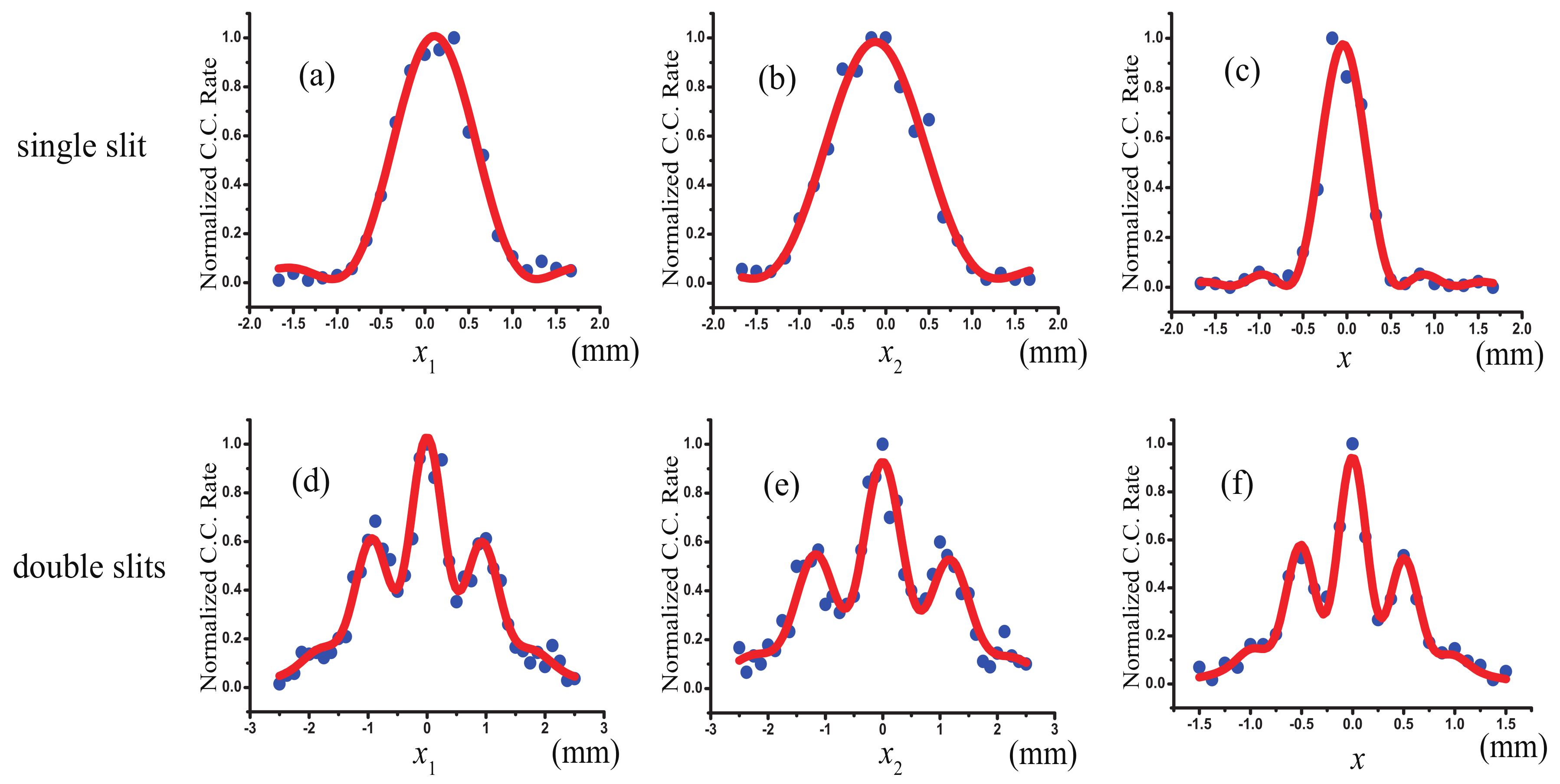
First, we study the diffraction of non-degenerate biphotons. The object is a single slit, the width of which is
mm. In the first measurement, the detector
is fixed, and detector
is scanned. The normalized coincidence counting rate distribution is shown in
Figure 2a as the function of coordinates of
on plane
. In the second measurement, the detector
is fixed, and detector
is scanned. The normalized coincidence counting rate distribution is shown in
Figure 2b as the function of coordinates of
on plane
. In the third measurement, the detector
and
are scanned synchronously. With the help of the beam splitter, it is equivalent to recording the distribution of diffracted biphotons using two-photon absorption (TPA) material on the Fourier transformation plane of the lens. The normalized coincidence counting rate distribution is shown in
Figure 2c as the function of the coordinates of detectors on their respective planes.
In the measurements of
Figure 2a,b, the results are the measurements of non-degenerate ghost diffraction [
10]. The measurement of
Figure 2c is the diffraction of non-degenerate biphotons through the single slit or the non-degenerate quantum lithography of the interference-diffraction pattern of the single slit. The FWHM of the diffraction pattern in
Figure 2a,c’s measurements are
mm,
mm and
mm, respectively. The ratio between them is 2.26:1.82:1. We notice that the ratio between wavelengths of the idler (788 nm), signal (633 nm) and pump light (351 nm) is 2.25:1.80:1.
We know that the classical imaging limit of a regular imaging system is determined by the size of the diffraction pattern of the effective optical aperture of the system. The above experiment shows that the FWHM of the diffraction pattern of the non-degenerate biphotons is narrower than those of signal and idler photons. The resolution of non-degenerate quantum lithography is improved compared to those of its constituent parts: signal and idler photons. In the following, we will try to understand the physics of these measurements, first qualitatively and then quantitatively.
3. Theory and Discussions
The purpose of quantum lithography is to increase the resolution of the image by using entangled photon pairs. The experiment reported in the above section is a proof-of-principle quantum lithography experiment with none-degenerate photon pairs. The connection between the experiment and the resolution enhancement is based on the Abbe theory of image formation [
11]. As known from Abbe, only a certain portion of the diffracted components generated by a object are intercepted by the aperture
L of an imaging device in a diffraction-limited imaging system. That is the reason why a diffraction-limited imaging system has finite resolution. In quantum lithography, entangled photon pairs are used to illuminate the object, and the interference-diffraction patterns of the object will be narrower compared to that of classical light. In our non-degenerate quantum lithography experiment, we show that the width of the diffraction pattern is narrower than that of classical light (shown in
Figure 2), which means that there are more higher diffraction orders collected. The image from the diffraction pattern via Fourier transform will have a higher resolution.
The measurements of
Figure 2a,b can be easily understood in Klyshko’s picture [
12]. For example, in the measurement of
Figure 2a the fiber tip 1 could be treated as a light source emitting photons at 633 nm backward to the BBO crystal. The crystal functions as a non-linear mirror, which turns the 633-nm photons into 788-nm photons and reflects them to the object. The 788-nm photons are diffracted by the single slit and pass through the Fourier lens to form the diffraction pattern in the detection planes. We should emphasize that the diffraction pattern only exists in the second-order correlation regime, and the single photon counting distributions on both
and
planes are nearly flat.
However, Klyshko’s picture cannot explain the measurement shown in
Figure 2c. To understand the measurement qualitatively, we need to use the concept of the diffraction of biphotons: the non-degenerate biphoton, comprising daughter photons with different wavelengths, is one object due to their internal binding (entanglement). It is diffracted by the single slit as a particle with bigger momentum than its constituent parts (signal and idler photons), that is the reason why the FWHM of the diffraction pattern in the third measurement is narrower than those in the first two measurements.
To interpret the experiment quantitatively and to find out why the de Broglie wavelength of non-degenerate biphotons is the same as the one of the pump, we need to calculate the second order correlation functions measured in our experiment. According to quantum optical theory, the second order correlation function is:
where
describes the quantum-mechanical state of the electromagnetic field on the output face of the crystal, for
,
is the positive frequency part of the electric field at the point
evaluated at time
and
.
In our experiments, the state of entangled light is a pure state, and we assume that the measurements have proceeded at the single photon level. Therefore, the
can be written in terms of the effective biphoton probability amplitude [
13,
14]:
where
A is the effective two-photon probability amplitude, which describes the joint detection of the biphoton.
stands for the entangled state,
where
,
and
are the angular frequencies of the signal photon, idler photon and laser pump, respectively.
and
stand for the transverse wave vectors of signal and idler photons, respectively.
is the phase mismatch in the direction of the pump, which equals
, and
L is the length of the nonlinear crystal.
Since there is a polarizing beam splitter (PBS) in the alignment, all the signal photons go to detector
, and all the idler photons go to detector
. The field operators at the detectors can be described in terms of annihilation operators of signal and idler photons at the surface of the nonlinear crystal, for example:
where
is the annihilation operator of a mode of the signal light field at the surface of the BBO crystal.
is the optical propagation function, which describes the propagation of the signal light from the surface of the crystal to detector
. The details of the calculation can be found in [
13,
15].
Combining Equations (
2) and (
3), the spatial part of the measured second order correlation function is:
where
is the optical transfer function describing the propagation of the idler photon from the surface of the crystal to detector
and
in our experiment. It is straight forward to show that the measured
is the Fourier transform of the aperture function [
9,
13]:
where
is the aperture function of the object.
The experimental results can be easily understood from Equation (
5). First of all, the measured
function can be interpreted as the result of the coherent superposition of two-photon probability amplitudes. In the measurement of
Figure 2a,
is fixed and
is scanned, which means the transformation parameter is
where
nm. In the measurement of
Figure 2b,
is fixed,
is scanned and the transformation parameter is
where
nm. In the measurement of
Figure 2c, both detectors are scanned (
), and the transformation parameter is
where
nm. From the above calculations, we can see why the ratio between FWHMs of diffraction patterns in three measurements equals (within experimental error) the ratio between the wavelength of signal, idler and pump.
We notice that when two detectors are scanned synchronously, the signal and idler photons behave like one particle, even if they have different wavelengths. The momenta of “two photons” are coherently added together due to the internal binding between them, and the momentum of the biphoton equals . The photonic de Broglie wavelength of the biphoton is then where h is Plank’s constant.
In the first experiment, we study the diffraction of non-degenerate biphotons. The non-degenerate biphotons—composed by signal photons and idler photons with different wavelength—are collinear with the pump and diffracted by the single slit. The distribution of the diffraction pattern manifests the de Broglie wavelength of the non-degenerate biphotons. However, people used to directly measure the de Broglie wavelength of a particle by making the particle interfere with itself [
1]. Therefore, we design the second experiment to study the interference of a non-degenerate biphoton with itself in a Young’s interferometer by replacing the single slit with a double slit. The measurements are similar to those in the first experiment. We first measure two different non-degenerate ghost interferences: in the first one, the detector
is fixed, and detector
is scanned, shown in
Figure 2d; in the second one, the detector
is fixed, and detector
is scanned, shown in
Figure 2e. In the third measurement, both detectors are scanned in their planes synchronously, shown in
Figure 2f. In three measurements, the distances between the maximums of interference patterns are measured, and the ratio between three distances is 2.34:1.88:1. The ratio between wavelengths of the idler (788 nm), signal (633 nm) and pump (351 nm) is 2.25:1.80:1. According to the Abbe theory of image formation, with the object illuminated by non-degenerate entangled photon pairs, the resolution enhancement is
-times compared to the one with classical 788-nm light; the resolution enhancement is
-times compared to the one with classical 633-nm light.
The experiment result shown in
Figure 2e is the direct measurement of the photonic de Broglie wavelength of non-degenerate biphotons. The double slit in the setup functions as a Young’s double slit interferometer. It is known that biphotons are strongly correlated both in momentum and position due to the entanglement. After generation, they could be any place on the output surface of the crystal. However, once a signal/idler is detected at one specific position on the output surface, its twin photon must be at the same position with
certainty [
16]. Since the double slit is very close to the output surface of the crystal, the generated signal-idler pairs can pass through either the upper slit or the lower slit together, and the chance the they pass through different slits is negligible. In the experiment, the photon counting rate is very low (∼
Hz), and it is reasonable to assume that there is only one pair of biphotons in the experimental scheme in each coincidence measurement. The interference-diffraction pattern measured when two detectors are scanned synchronously is the result of the interference between a biphoton and itself. In other words, it is the interference between two two-photon probability amplitudes,
where
and
represent two different ways to trigger a two-photon coincident counting event, respectively.


