Article

Joint Interference and Phase Alignment among Data Streams in Multicell MIMO Broadcasting

1
Department of Electrical Engineering, University of Engineering & Technology, Peshawar 814 KPK, Pakistan
2
Integrated Management Coastal Research Institute, Universitat Politecnica de Valencia, C/ Paranimf nº 1, Gandia, 46730 Valencia, Grao de Gandia, Spain
3
Institute of Telecommunications and Multimedia Applications (iTEAM), Universitat Politècnica de València, Camino Vera n/n, 46022 Valencia, Spain
*
Author to whom correspondence should be addressed.
Appl. Sci. 2018, 8(8), 1237; https://doi.org/10.3390/app8081237
Submission received: 29 June 2018 / Revised: 16 July 2018 / Accepted: 24 July 2018 / Published: 26 July 2018

Abstract

:
For the problem of channel state information (CSI) delay and error, this paper proposes a joint interference and phase alignment algorithm based on Bayesian estimation and power allocation among data streams for multicell, multiple-input multiple-output broadcast channels (MIMO-BC). Firstly, the sender obtains the best estimate of the current CSI through Bayesian estimation. Secondly, the interference suppression matrix is designed by maximizing the ratio of the desired signal power to the intercell interference plus noise ratio (SINR) in the forward link, and in the reverse communication, by maximizing the SINR design precoding. Further, the water-filling algorithm is combined to optimize power allocation among data streams. Finally, the phase alignment is used to rotate the interference between data streams into the signal space of the target receive data stream, thereby enhancing the received power of the target data stream. Simulation results show that the proposed algorithm has certain performance advantages over other algorithms, whether it is ideal CSI or delay and error CSI.

1. Introduction

Multiple-input multiple-output (MIMO) is a technology which can make great enhancements in terms of the overall throughput of the network [1]. How to eliminate the interference of cell edge users in the multicell, multiuser MIMO downlink is a research hotspot in recent years. Different from other transmission technologies in the interference channel, the interference alignment (IA) technique can effectively eliminate the cochannel interference and increase the system capacity [2]. The core idea of the IA is to arrange multiple interference signals on the transmitting side to interference subspaces with less than the number of interfering users. At the receiving end, only simple zero-forcing processing is required to make each user obtain nearly half of the interference-free spectrum. Currently, the interference scheduling algorithm is mostly based on complete and accurate channel state information (CSI). However, in an actual communication system, since the channel may produce errors in the estimation or measurement, the receiving end cannot completely suppress other base station interference which causes system performance loss. This paper gives the solution to the existing problem by proposing a joint interference and phase alignment algorithm based on Bayesian estimation and power allocation among data streams. In the proposed algorithm, the transmitter deploys Bayesian estimation to acquire the best estimate of the current CSI. Then, the interference suppression matrix is determined by maximizing the SINR in the downlink communications. The precoding is designed by maximizing the SINR of the receiver at the uplink communication. Next, the water-filling algorithm is deployed for power distribution due to which more power falls on better subchannels. Finally, the received power of the target data stream is increased using the phase alignment to rotate the interference between data streams into the signal space of the target receive data stream. Simulations results show that the proposed algorithm has obvious performance enhancement and outperforms the exiting IA algorithms. The main contributions of the paper are as follows:
  • Proposed joint IA and Phase Alignment algorithm that effectively improve the performance of MIMO systems
  • Deployed Bayesian estimation for efficient utilization of the IA algorithm
  • Improved the downlink and uplink SINR of the MIMO system by incorporating such algorithm
  • Reduced the cochannel interference to adequate level
  • Improved the system capacity, bit error rate (BER), and reliability
The rest of the paper is organized as follows. Section 2 provides the literature review of the proposed research work. Section 3 discusses the system model. Section 4 gives the Bayesian modeling of the delay error CSI. Section 5 explains the Interference Alignment algorithm for MIMO-BC. Section 6 presents the algorithm performance analysis. Section 7 provides the simulations results and analysis while Section 8 concludes the paper.

2. Related Work

At present, most Interference Alignment (IA) algorithms rely on ideal Channel State Information (CSI) [1,2]. However, in the actual wireless communication, the CSI obtained by the sender often has time delay and error, so that the ideal IA cannot be realized [3,4]. In recent years, researchers have studied the IA of time delay CSI and error CSI separately, while less research has been conducted on the case of CSI with both time delay and error (time delay error CSI).
Firstly, in terms of latency CSI, the literature [5,6] discusses the influence of time delay on the degree of freedom of the K-user interference network and the three-user MIMO Gaussian network. It also considers the imperfect CSI case. Literature [7] gives the IA algorithm under time-varying channel and analyzes the degree of freedom. The literature [8,9] gives the backtracking algorithm applicable to three-user interference channels and two-cell multiple access channels under time delay CSI. The literature [9] pointed out that the delay CSI can obtain better performance than that without CSI. When the number of users changes and the delay is unknown, in [10] the receiver uses the current CSI and delay CSI and previous precoding to update the current precoding step by step, providing a low-complexity adaptive beam design scheme. Under the classical time delay channel model, the literature [11] predicts the channel by the minimum mean square error (MMSE) and least square error (LSE) and gives a robust IA scheme.
Second, in terms of error CSI, the literature [12] gives a robust IA based on the MMSE criterion and analyzes the bit error rate (BER). The literature [13] gives the upper and lower limits of the mutual information of the system when the base station knows the noisy CSI. The IA algorithm of weighted MMSE is given in [14]. In [15], based on the error CSI statistical model, a robust minimum interference leakage algorithm is given. The literature [16] carries on QR decomposition to the joint error channel, reduces the intensity of the interference, and improves the performance of the algorithm under error CSI. The literature [17] derives the Max-SINR with stochastic CSI Error Knowledge (Max-SINR-SCEK) algorithm from the error CSI statistical model. Under error CSI, the literature [18] aligns the phase of the sender signal and the receiver signal and gives a robust joint interference phase alignment algorithm under MIMO-MAC.
It can be seen that in the time delay CSI, the literature [5,6] analyzed the degree of freedom, and no concrete implementation was given. The literature [7,8] needed the number of known users and the current delay CSI, so it is difficult to be applied in practice. The backtracking IA in [8,9] required the channel to have interlaced block fading characteristics. The systems in [10,11] had a large overhead. In the error CSI, the literature [12,13,14] did not consider the data flow correlation and power allocation. The literature [15] did not consider the effect on useful signals. Interference leakage in the literature [16] has become a major factor in limiting channel capacity, and there is no power allocation. Literature [17] required that the sender has more antennas and high sensitivity to error CSI. Literature [18] did not consider how to increase the power of useful signals.
In summary, in the case of time delay error CSI, this paper gives the solution to the existing problem by proposing a joint interference and phase alignment algorithm based on Bayesian estimation and power allocation among data streams.

3. System Model

Figure 1 shows a G-cells MIMO-BC Interference channel model. There are K users per cell and each user is equipped with N (receiving) antennas. Each base station is equipped with M antennas. k g indicates the user k in cell g. Its degree of freedom is d k g ,   k ,   g . In order to maximize the degree of freedom of the system, we may set d 1 g = d 2 g = = d k g = d . It is assumed that the channels between the transmit and receive pairs on the same frequency at the same time are flat fading and the channel coefficients are independent and identically distributed.
Then, the received signal of user k in cell g is:
S ^ k g = U k g H H k g , g V k g S k g + l = 1 , l k K U k g H H k g , g V l g S l g + j = 1 ,   j g G l = 1 K U k g H H k g , j V l j S l j + U k g H n k g
Among them, S l j d × 1 is the transmission signal of user l in cell j , which satisfies E { S l j H S l j } = P ; V l j M × d is the precoding of user l j , which satisfies t r a c e { V l j V l j H } = d ; U k g N × d is the interference suppression of user k g matrix; H k g , j N × M is a channel link from base station j to user k g , which obeys a complex Gaussian distribution with a mean of 0 and a variance of 1. n k g N × 1 is a Gaussian White Noise with a variance of δ n 2 .
From Equation (1), it can be seen that the ideal interference alignment should satisfy:
{ r a n k ( U k g H H k g , g V k g ) = d ,     k ,   g U k g H H k g , g V l g = 0 ,     l k U k g H H k g , j V l j = 0 ,     j g
When there is a time delay and error in H k g , j (   k ,   g ) , Equation (2) will not hold, and a robust IA scheme needs to be designed.

4. Bayesian Estimation of Delay Error CSI

In a communication system that needs feedback CSI, due to limited hardware performance and feedback CSI propagation delay, the CSI of the sending end often has both time delay and error. This section will use a Bayesian algorithm to predict CSI.
The CSI vectors L k g , j τ and L k g , j of the true channel H k g , j and the delay channel H k g , j τ are, respectively:
L k g , j τ = v e c ( H k g , j τ )
L k g , j = v e c ( H k g , j )
Let the time-varying channel satisfy the Jakes model [19], then the covariance of L k g , j τ and L k g , j satisfies the joint Gaussian distribution, namely E { L k g , j L k g , j τ H } = ρ I T , where T = N × M , ρ = J 0 ( 2 π f d τ ) is the correlation coefficient, τ is the delay, f d is the maximum Doppler shift, and J 0 ( x ) is the first zero-order Bessel function. At this point, the statistical model of the equivalent channel is:
L k g , j = ρ L k g , j τ + σ k g , j
where L k g , j and L k g , j τ obey a complex Gaussian distribution with a mean of 0 and a variance of 1. ξ k g , j and L k g , j τ are mutually independent, and ξ k g , j C N ( 0 ,   φ ξ 2 ) ; φ ξ 2 = ( 1 | ρ | 2 ) I T .
Here, the receiver only knows the current time and the CSI of the estimation error exists (i.e., L ^ k g , j ) and the sender only knows the CSI before the time τ and there is an estimation error (i.e., L ^ k g , j τ ).
Thus, when L k g , j τ and L k g , j have estimated errors e k g , j τ and e k g , j , respectively, the corresponding expression should be:
L ^ k g , j τ = L k g , j τ + e k g , j τ
L ^ k g , j = L k g , j + e k g , j
Among them, e k g , j τ and e k g , j satisfy the complex Gaussian distribution with a mean of 0 and a variance of δ e 2 .
From Equations (5)–(7), we can see that:
L ^ k g , j τ ,   L ^ k g , j C N ( 0 ,   d i a g ( 1 + δ e 2 ) T × T )
E { L k g , j L ^ k g , j τ H } = ρ I T
E { L k g , j L ^ k g , j H } = I T
Here, we use the Bayesian algorithm [20] to estimate L ^ k g , j τ (real-time CSI) from L k g , j (time delay error CSI). First, calculate the conditional probability E ( L k g , j | L ^ k g , j τ ) of L k g , j , and the conditional covariance matrix D ( L k g , j | L ^ k g , j τ ) as:
E ( L k g , j | L ^ k g , j τ ) = E ( L k g , j L ^ k g , j τ H ) × E ( L ^ k g , j τ L ^ k g , j τ H ) 1 L ^ k g , j τ = ρ ( d i a g ( 1 + δ e 2 ) T × T ) 1 L ^ k g , j τ
D ( L k g , j | L ^ k g , j τ ) = E ( L k g , j L k g , j H ) E ( L k g , j L ^ k g , j τ H ) × E ( L ^ k g , j τ L ^ k g , j τ H ) 1 E ( L ^ k g , j τ L ^ k g , j H ) = I T | ρ | 2 ( d i a g ( 1 + δ e 2 ) T × T ) 1
For this reason, under the time delay error CSI, the actual channel H k g , j . can be modelled as:
H k g , j = ρ 1 + δ e 2 H ^ k g , j τ H + E k g , j
Among them, E k g , j is the error CSI factor which obeys a complex Gaussian distribution with a mean of 0 and a variance of 1 | ρ | 2 1 + δ e 2 .

5. MIMO-BC Robust Interference Alignment

5.1. Robust Interference Alignment with Power Distribution among User Data Streams

Due to the asymmetry of the MIMO-BC channel, the performance of the algorithm [1] is not ideal. Therefore, in this paper, when designing the receiving filter, only the intercell interference is concerned; when designing the transmitting filter, intercell and intracell interference (excluding interfering signals between user data streams) are handled.
In the downlink communication, for the user k g , the interference suppression matrix is designed by maximizing the ratio of the desired signal power to the intercell interference power:
U ^ k g = arg   max U ^ k g M × d U ^ k g H Z k g U ^ k g U ^ k g H Q k g U ^ k g
where Z k g and Q k g are vectors which are obtained by:
Z k g = H k g , g V ^ k g S k g S k g H V ^ k g H H ^ k g ,   g H = P d ( ρ 1 + δ e 2 ) 2 H ^ k g , j τ V ^ k g V ^ k g H H ^ k g , j τ H + P ( 1 | ρ | 2 1 + δ e 2 ) I N
Q k g = j = 1 j g G l = 1 K H k g , j V ^ l j S l j S l j H V ^ l j H H ^ k g ,   j H + δ n 2 I N = j = 1 j g G l = 1 K P ρ 2 d ( 1 + δ e 2 ) 2 H ^ k g , j τ V ^ l j V ^ l j H H ^ k g ,   j τ H + [ ( G 1 ) K P ( 1 | ρ | 2 1 + δ e 2 ) + δ n 2 ] I N
According to Rayleigh entropy [21], the optimal interference suppression matrix is expressed as:
U ^ k g = v max d { ( Q k g ) 1 Z k g }
where v max d ( · ) denotes the unit eigenvector corresponding to the first d largest eigenvalues of the evaluation matrix.
In the uplink communication, for the user k g , the precoding matrix is designed by maximizing the SNR of the user k g as follows:
V ^ k g = arg   max V ^ k g M × d V ^ k g H ( A k g ) V ^ k g V ^ k g H ( B k g ) U ^ k g
where vectors A k g and B k g are calculated as:
A k g = H k g , g H U ^ k g S k g S k g H U ^ k g H H k g , g = P d ( ρ 1 + δ e 2 ) 2 H ^ k g ,   j τ H U ^ k g U ^ k g H H ^ k g ,   j τ + P ( 1 | ρ | 2 1 + δ e 2 ) I M
B k g = l = 1 l k K m = 1 d P ρ 2 d ( 1 + δ e 2 ) 2 H ^ g ,   l g τ H u l g m u l g m H H ^ g ,   l g τ                 + j = 1 j g G l = 1 K m = 1 d P ρ 2 d ( 1 + δ e 2 ) 2 H ^ g ,   l j τ H u l j m u l j m H H ^ g ,   l j τ              + [ ( G K 1 ) P ( 1 | ρ | 2 1 + δ e 2 ) + δ n 2 ] I M
According to Rayleigh entropy [21], the optimal interference suppression matrix V ^ k g is:
V ^ k g = v max d { ( B k g ) 1 A k g }
For user k g , the amount of mutual information [22] between the sent data stream S k g and the received data stream S ^ k g can be expressed as:
I ( S k g , S ^ k g ) = log 2 det { I d k g + F E 1 }
where F and E are the matrices which are obtained by the signal components and their Hermitian as follows:
F = U ^ k g H H k g , g V k g W k g S k g S k g H W k g H V k g H H k g ,   g H U ^ k g
E = j = 1 j g G l = 1 K P ρ 2 d ( 1 + δ e 2 ) 2 U ^ k g H H ^ k g ,   j τ V ^ l j V ^ l j H H ^ k g ,   j τ H U ^ k g                 + l = 1 l k K P ρ 2 d ( 1 + δ e 2 ) 2 U ^ k g H H ^ k g ,   g τ V ^ g j V ^ g j H H ^ k g ,   g τ H U ^ k g              + [ ( G 1 ) P ( 1 | ρ | 2 1 + δ e 2 ) + δ n 2 ] I d k g
The diagonal matrix W k g is the power distribution matrix and satisfies I ( W k g W k g H ) = d .
According to matrix theory, Equation (22) can be written as:
I ( S k g , S ^ k g ) = log 2 det { I d k g + X k g F X k g H }
Among them, X k g is the matrix that meets the following condition:
X k g H X k g = E 1
At this point, the received symbol S ^ k g can be written as:
S ^ k g = X k g U ^ k g H H k g , g V ^ k g W k g S + n k g ´
Among them, n k g ´ is the complex Gaussian white noise vector and obeys the distribution C N ( 0 d k g ,   I d k g ) ; Y k g = X k g U ^ k g H H k g , g V ^ k g is the equivalent MIMO channel with interference alignment.
The mth largest singular value of the equivalent channel is:
Λ k g , m = eig m ascend { Y k g Y k g H }
Among them, eig m ascend ( · ) denotes the mth largest eigenvalue of the matrix.
When the power of the user k g is P , the optimal solution is the water-filling method power allocation of the MIMO channel [23]:
P k g m P = { 1 γ 0 1 γ m ,   γ m > γ 0 0 ,   γ m < γ 0
Among them, γ 0 is the threshold value; P k g m is the power that should be allocated for the mth data stream of user k g .
Suppose the d singular values of the equivalent channel matrix Y k g corresponding to user k g are Λ k g , 1 ,   Λ k g , 2 ,   ,   Λ k g , d , and they are arranged in descending order. The SNR corresponding to each subchannel at full power is γ 1 = P ( Λ k g , 1 ) 2 ,   γ 2 = P ( Λ k g , 2 ) 2 , ,   γ d i = P i ( Λ k g , d ) 2 . Then calculate the threshold γ 0 as:
m = 1 d ( 1 γ 0 1 γ m ) = 1
At this time, the optimal power allocation of user k g data stream is P k g m = P ( 1 γ 0 1 γ m ) .
After the data flow of user k g is allocated for power, it will satisfy Equation (31):
W k g S k g S k g H W k g H = P d diag ( P k g 1 ( P / d ) ,   P k g 2 ( P / d ) , ,   P k g d ( P / d ) )
Further, the power allocation matrix W k g is:
W k g = diag ( P k g 1 ( P / d ) ,   P k g 2 ( P / d ) , ,   P k g d ( P / d ) )

5.2. Phase Alignment

In the time delay error CSI, the phase alignment is used to rotate the interference between the data streams into the signal space of the target data stream to enhance the received power of the target data stream [24].
After processing in Section 5.1, the signal for user k g is:
S ^ k g = H ¯ k g S k g + j = 1 j k K H ¯ j g S j g + j = 1 j g G l = 1 K H ¯ l j S l j + n ¯ k g
where H ¯ k g = U ^ k g H H k g , g V ^ k g W k g ; H ¯ j g = U ^ k g H H k g , g V ^ j g W j g ; H ¯ l j = U ^ k g H H k g , j V ^ l j W l j ; n ¯ k g = U ^ k g H n k g .
Here, the rate is given by:
R k g = E ( H ¯ k g ) E ( H ¯ k g H )
Based on the MMSE criterion, the transmitted signal and the received signal are phase aligned [18], and the interference signal is reconstructed. At this time, the resulting constraint expression is:
l k g ´ = min E { R k g θ c k g ( H ¯ k g Ψ k g θ c k g + n ¯ k g ) 2 }
s . t . R k g θ = | R k g | ( c k g c k g H )
Among them, c k g d k g × 1 consists of MPSK constellation points and satisfies c k g H c k g = d k g , and denotes the Hadamard product of the matrix. Solving Equation (35) we get:
Ψ k g θ = E ( H ¯ k g H ) R k g 1 R k g θ
where Ψ k g θ is the estimated rate matrix of the MPSK constellation. Thus, the transmit signal of the user k g can be expressed as:
S k g = g k g θ Ψ k g θ c k g
s . t . g k g θ = 1 t r a c e [ ( R k g θ ) 2 R k g 1 ]
From such results, it is possible to minimize the constraint (35).

5.3. Algorithm Summary

The joint interference and phase alignment algorithm based on Bayesian estimation and data stream power allocation is summarized as follows in Algorithm 1:
Algorithm 1. Joint interference and phase alignment.
Step 1: By making the Bayesian estimation of Equation (13), the receiving end gets better for accurate CSI.
Step 2: Through iterations of Equations (17) and (21) until convergence, a robust precoding V ^ and interference suppression matrix U ^ are obtained.
Step 3: Distribute power between user data streams using Equation (32) to optimize system mutual information.
Step 4: By aligning the phase of the transmitted symbol and the received symbol in Section 5.2, the received data stream obtains a high diversity gain to enhance the received power of the target data stream.

6. Algorithm Performance Analysis

6.1. Algorithm Convergence Analysis

From Section 4, we can see that in the downlink, the interference suppression matrix is designed by Equation (14) to maximize the ratio of the desired signal power to the intercell interference power, and the precoding matrix is designed by Equation (18) in the uplink. The SINR is maximized, and the process is repeated until convergence. In this process, both the interference space and the signal quality are improved. In order to further improve the signal quality, the 4-in-1 power allocation algorithm is used to optimize the mutual information of the system. On the other hand, the maximal ratio combined signal flow is achieved through the phase alignment in Section 5.2 to improve the received power of the target signal stream. It can be seen that through the iterative operations of the downlink and the uplink, the compressed interference space is gradually rotated, and the signal quality is improved through power allocation and phase alignment, and the signal to interference ratio is gradually improved.
The convergence simulation is given in Section 7.4 of this paper to further verify the convergence and feasibility of the proposed algorithm.

6.2. Time Delay Error CSI System and Rate and Bit Error Rate Analysis

The actual channel is denoted by H to analyze the performance of the system. From Section 5.2, it can be seen that in the actual channel environment, the actual received signal of the user k g is:
S ^ k g = H k g , g Ψ k g θ c k g + U ^ k g H × { l = 1 l k K H k g , g V ^ l g W l g S l g + j = 1 j g G l = 1 K H k g , j V ^ l j W l j S l j } + U ^ k g H n k g
The true R k g θ corresponding to Equation (34) is:
R ¯ k g θ = H ¯ k g Ψ k g θ = H ¯ k g ( E ( H ¯ k g H ) R k g 1 R k g θ )
From Equation (13) we know that:
E [ R ¯ k g θ ] = R k g θ
So, the received signal of the wth freedom of user k is:
y k g w g k g θ c w x = 1 d k | ρ w , x | + u ^ k g w H × { l = 1 l k K H k g , g V ^ g j W g j S g j + j = 1 j g G l = 1 K H k g , j V ^ l j W l j S l j } + u ^ k g w H n k g
where ρ w , x is the ( w , x ) element of R k g .
The residual interference can be expressed as:
J k g u ^ k g w H { l = 1 l k K H k g , g V ^ g j W g j S g j ( H k g , g V ^ g j W g j S g j ) H + j = 1 j g G l = 1 K H k g , j V ^ l j W l j S l j ( H k g , j V ^ l j W l j S l j ) H } u ^ k g w
In the case of progressively higher SNR, Equation (13) is brought into Equation (42), therefore:
E ( J k g ) P ( G K 1 ) ( 1 | ρ | 2 1 + δ e 2 )
The corresponding output average SINR is:
SIN R k g w = E { ( g k g θ ) 2 } ( δ n ) 2 + J k g × E { ( x = 1 d k g | ρ w , x | ) 2 }
The sum rate of the user k g can be expressed as:
R k g = w = 1 d k g log 2 { 1 + SIN R k g w } = w = 1 d k g log 2 { 1 + E { ( g k g θ ) 2 } ( δ n ) 2 + J k g × E { ( x = 1 d k g | ρ w , x | ) 2 } }
For user k g , the average BER of M-PSK modulation can be calculated using Equation (46):
P M k g = w = 1 d k g erfc ( SIN R k g w sin ( π M ) ) d k g

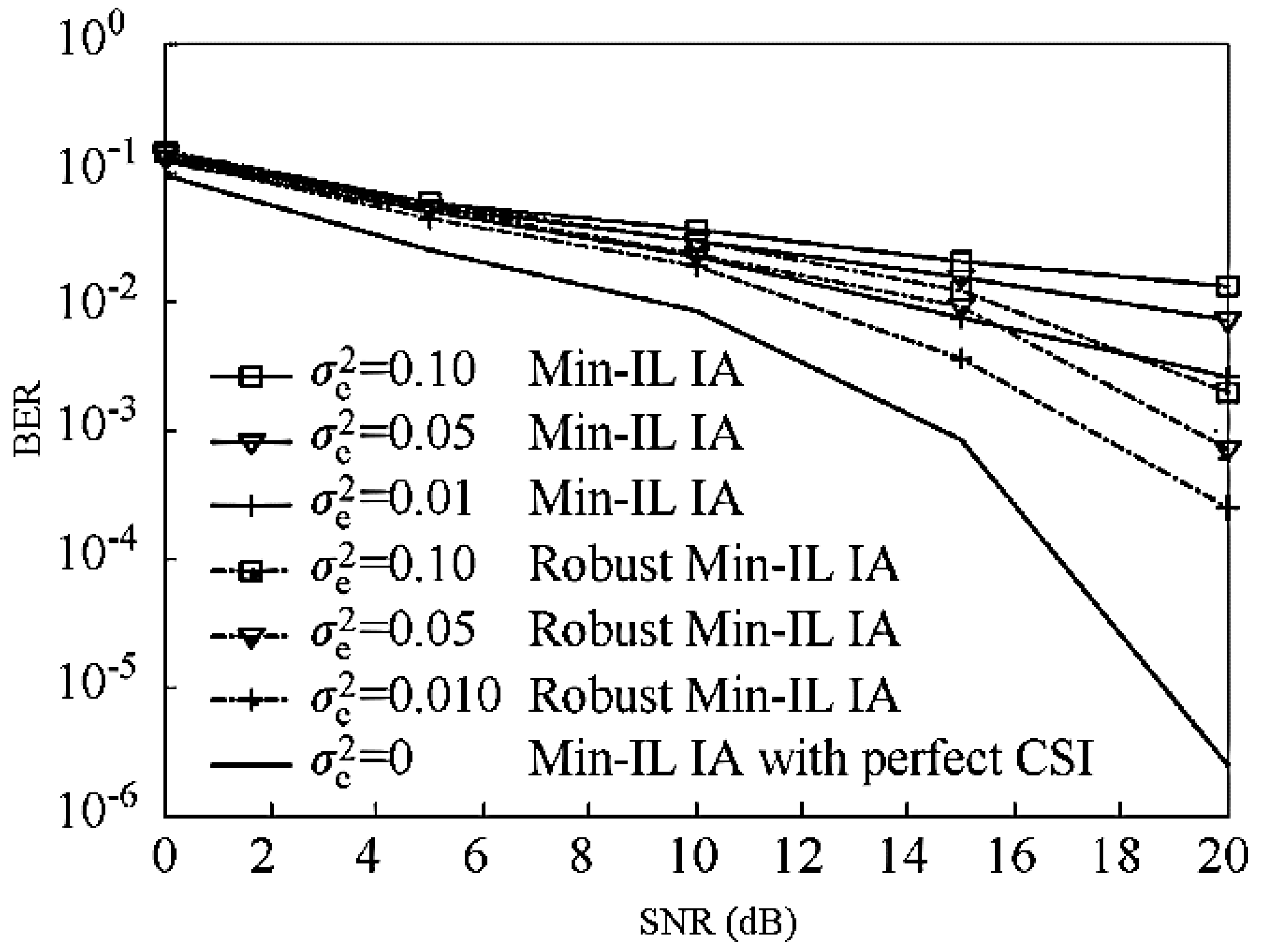
6.3. Performance Analysis under Nonideal CSI

At progressively high SNR, nonideal CSI with delay τ and error variance δ e 2 , the system rate loss is expressed as:
Δ R = E ( R perfect   CSI ) E ( R imperfect   CSI ) g = 1 G k = 1 K w = 1 d k g log 2 ( E ( J k g ) + δ n 2 δ n 2 )
In order to guarantee the freedom of the system, the loss of the system capacity is required to be a constant, defined as ε which is expressed as:
ε = G K d log 2 ( E ( J k g ) + δ n 2 δ n 2 )
We bring Equation (43) into (48) and obtain:
| ρ | 2 1 + δ e 2 = 1 ( 2 ε G K d 1 ) δ n 2 ( G K 1 ) P
From Equation (49), it can be seen that in order to guarantee the ideal degree of freedom, it is required that as the power P increases, | ρ | 2 / ( 1 + δ e 2 ) becomes closer and closer to 1, that is, the channel becomes more and more ideal.

7. Simulation Results and Analysis

We have used MATLAB for simulation and analysis. In the case of ideal CSI and delay error CSI, the algorithm of this paper is combined with MAX-SINR-SCEK [17], MIN-IL [17], and the literature [11], and the system capacity, bit error rate (BER), and convergence are simulated for comparison.
Consider the system configuration [ G ,   K ,   d ,   M ,   N ] , that is, G cell, K users per cell, the number of data streams (degrees of freedom) sent by each user is d , the number of transmit antennas is M , and the number of receive antennas is N . Assume that all channels are flat fading channels and satisfy the complex Gaussian distribution with a mean of 0 and a variance of 1. When comparing the time delay error CSI, assume that the symbol duration is 0.5 ms, and consider the delay is 1 symbol time; the carrier frequency band is 2 GHz, the user receiving end moves at 20 km/h, and the correlation coefficient ρ = 0.9966. The variance σ e 2 of the channel error is taken as 0.001. Table 1 shows the simulation parameters which are used for performance evaluation of the proposed algorithm.

7.1. Average System Capacity under Ideal CSI

As shown in Figure 2, the channel capacity of several typical MIMO-BC algorithms is compared in ideal CSI. The proposed algorithm only focuses on intercell interference when designing the receive filter and handles intercell and intracell interference (excluding interference between user data streams) when designing the transmit filter and uses a water-filling scheme to optimize power allocation, and finally uses phase alignment. The interference between data streams is rotated into the signal space of the target receiving data stream, thereby enhancing the receiving power of the target data stream.
However, the MAX-SINR-SCEK algorithm in the literature [17] focuses on intercell interference, but the transmit filter needs to deal with intercell and intracell interference as well as interference between its own data streams. It needs to process more interference than this algorithm. For this reason, the proposed algorithm is better under the same environment configuration. In addition, the minimum interference leakage (MIN-IL) algorithm in [17] requires more antennas at the receiving end which is not practical in practical environments. Careful analysis shows that under MIMO-BC, the receiver needs to process less interference (from the neighboring base station), and the sender (usually the base station) needs to avoid interference to neighboring cell users and other users in the cell. More interference is handled, so it is more practical and reasonable to configure more antennas at the sending end to handle the interference. For comparison, under the same system configurations, the proposed algorithm is also better than the MIN-IL algorithm of [17].

7.2. Average System Capacity under Time Delay Error CSI

As shown in Figure 3, in nonideal CSI, the capacity of several typical algorithms is compared when configured as [2,2,4,13,8]. In time delay error CSI, the proposed algorithm has more room for handling interference and delay error, and minimizes the effects of interference and delay errors, further combining power allocation and phase alignment to improve signal quality. So, the proposed algorithm is better than the literature [17] MAX-SINR-SCEK algorithm. The literature [11] adopts MMSE and LSE high-order predicting channel, and although it can improve the channel quality under the delay error CSI to a great extent, the improvement is relatively limited and its performance is inferior to the proposed algorithm.

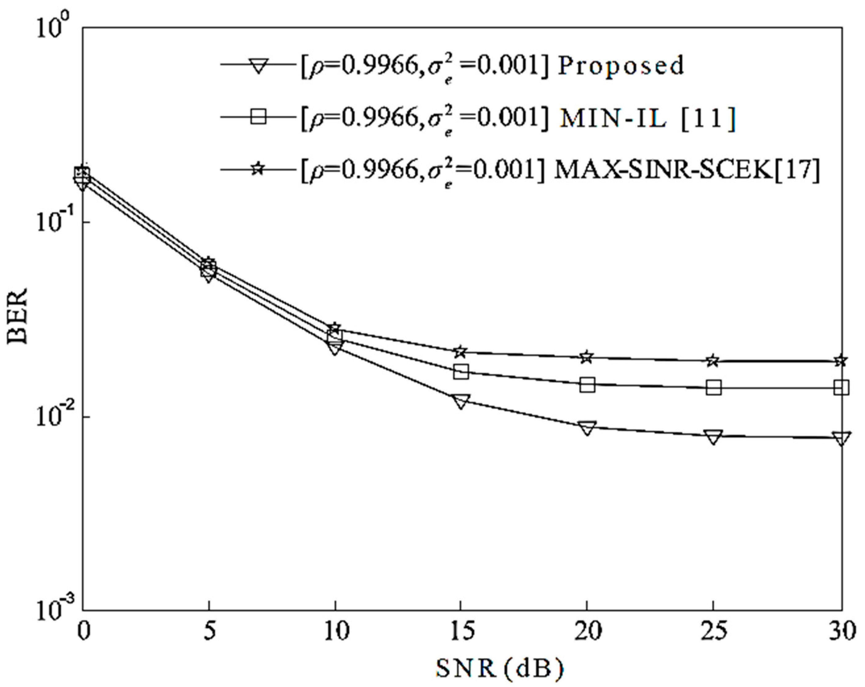
7.3. BER with Time Delay Error CSI

In time delay error CSI, Figure 4 simulates the BER performance of several typical algorithms when configured as [2,2,4,13,8]. When using QPSK for modulation, the proposed algorithm uses power allocation and aligns the phase of the transmitter and receiver signals to reconstruct the interference into a green energy source, which enhances the power of the desired symbol, and BER is greatly improved. The BER of the proposed algorithm is lower than the algorithms of literature [11,17].

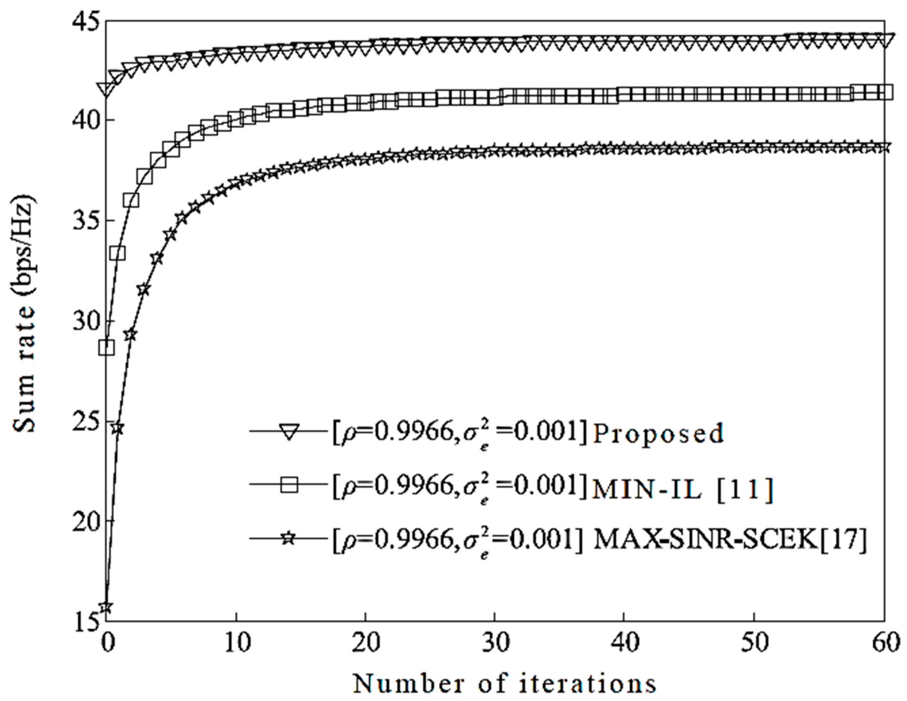
7.4. Convergence Time Delay Error CSI

When configured as [2,2,4,13,8], Figure 5 shows the relationship between the average system capacity and the number of iterations when the transmitted power of each user is 5 dB. As can be seen from the figure, in the time delay error CSI the user sends when the output power is 5 dB, the average system capacity of the proposed algorithm and that of literature [11] are convergent for about 20 iterations, while the MAX-SINR-SCEK algorithm converges approximately 23 times. It can be seen that the proposed algorithm improves the performance of the system without increasing the number of iterations and further confirms the convergence and feasibility of the algorithm.

7.5. Average System Capacity and BER under Time Delay Error CSI with Different Number of Cells and Users Configurations

As shown in Figure 6, in nonideal CSI, the capacity of several typical algorithms is compared when configured as [7,10,4,13,8] and [3,4,4,13,8]. In time delay error CSI, the proposed algorithm has more room for handling interference and delay error, and minimizes the effects of interference and delay errors, further combining power allocation and phase alignment to improve signal quality. So, the proposed algorithm is better than the literature [17] MAX-SINR-SCEK algorithm. The literature [11] adopts MMSE and LSE high-order predicting channel, and although it can improve the channel quality under the delay error CSI to a great extent, the improvement is relatively limited and its performance is inferior to the proposed algorithm. Furthermore, it is obvious from Figure 5 that the proposed algorithm with [7,10,4,13,8] configuration has high sum rate as compared to its other configuration [3,4,4,13,8]. Moreover, both configurations of the proposed IA algorithm outperform Literature [11,17] algorithms which clearly indicates its benefits over the existing algorithms.
Figure 7 simulates the BER performance of several typical algorithms when configured as [7,10,4,13,8] and [3,4,4,13,8]. When using QPSK for modulation, the proposed algorithm uses power allocation and aligns the phase of the transmitter and receiver signals to reconstruct the interference into a green energy source, which enhances the power of the desired symbol, and BER is greatly improved. The BER of the proposed algorithm is lower than the algorithms of literature [11,17]. Furthermore, the BER of the proposed algorithm when configured as [7,10,4,13,8] has much better performance in both ideal and delay error CSI as compared with its other configuration [3,4,4,13,8] and Literature [11,17]. Both configurations show overall better BER performance than the existing algorithms which makes it an attractive candidate for reducing the interference among user data streams in MIMO systems.

8. Conclusions

This paper proposes a robust joint interference and phase alignment scheme based on Bayesian estimation and power distribution among user data streams in the actual MIMO broadcasting communication system. The proposed solution is provided to overcome the simultaneous error and time delay CSI. Theoretical analysis and simulations show that the proposed algorithm improves the system capacity of the system, improves the BER performance, and effectively reduces the impact of time delay CSI on system performance, which indicates its robustness and potential as compared with the existing state-of-the-art algorithms. Future work extensions to this work are to consider a massive number of antennas at the base station and tens of antennas at the user equipment and analyze various important metrics such as energy efficiency, computational complexity, and attenuation under different deployment scenarios. Furthermore, the instantaneous and statistical CSI can be incorporated as an extension of such work so that the system performance evaluation is determined in more detail and from other aspects.

Author Contributions

W.S. analyzed the research work and performed experimentations, S.W.S. provided extensive technical support throughout the research work, J.L. provided extensive support in the theoretical analysis, and I.B. provided the results validation and conclusion. He also provided support in research funding.

Funding

This work has been partially supported by the “Ministerio de Economía y Competitividad” in the “Programa Estatal de Fomento de la Investigación Científica y Técnica de Excelencia, Subprograma Estatal de Generación de Conocimiento” within the project under Grant BIA2017-87573-C2-2-P.

Conflicts of Interest

The authors declare no conflict of interest.

References

  1. Khan, I.; Zafar, M.H.; Jan, M.T.; Lloret, J.; Basheri, M.; Singh, D. Spectral and Energy Efficient Low-Overhead Uplink and Downlink Channel Estimation for 5G Massive MIMO Systems. Entropy Inf. Theory 5G Technol. 2018, 20, 92. [Google Scholar] [CrossRef]
  2. Jia, G.; Han, G.; Li, A.; Lloret, J. Coordinate channel-aware page mapping policy and memory scheduling for reducing memory interference among multimedia applications. IEEE Syst. J. 2015, 11, 2839–2851. [Google Scholar] [CrossRef]
  3. Khan, I.; Singh, M.; Singh, D. Compressive Sensing-Based Sparsity Adaptive Channel Estimation for 5G Massive MIMO System. Appl. Sci. Comput. Sci. Electr. Eng. 2018, 8, 754. [Google Scholar] [CrossRef]
  4. Khan, I.; Singh, D. Efficient compressive sensing based sparse channel estimation for 5G massive MIMO systems. Elsevier AEU-Int. J. Electr. Commun. 2018, 89, 181–190. [Google Scholar] [CrossRef]
  5. Noam, Y.; Goldsmith, A.J. Blind Null-Space Learning for MIMO Underlay Cognitive Radio with Primary User Interference Adaptation. IEEE Trans. Wirel. Commun. 2013, 12, 1722–1734. [Google Scholar] [CrossRef]
  6. Tsinos, C.G.; Berberidis, K. Blind Opportunistic Interference Alignment in MIMO Cognitive Radio Systems. IEEE J. Emerg. Sel. Top. Circ. Syst. 2013, 3, 626–639. [Google Scholar] [CrossRef]
  7. Tsinos, C.G.; Berberidis, K. Blind Opportunistic Interference Alignment in Cognitive Radio Systems. In Proceedings of the 2013 IEEE International Conference on Communications (ICC), Budapest, Hungary, 9–13 June 2013; pp. 4880–4884. [Google Scholar]
  8. Abdulkadir, Y.; Simpson, O.; Nwanekezie, N.; Sun, Y. Space-time opportunistic interference alignment in Cognitive radio networks. In Proceedings of the 2016 IEEE Wireless Communications and Networking Conference, Doha, Qatar, 3–6 April 2016; pp. 1–6. [Google Scholar]
  9. Maleki, H.; Jafar, S.A.; Shamai, S. Retrospective interference alignment over interference networks. IEEE J. Sel. Top. Signal Process. 2012, 6, 228–240. [Google Scholar] [CrossRef]
  10. Shin, W.; Han, Y.; Lee, J.; Lee, N.; Heath, R.W. Retrospective interference alignment for two-cell uplink MIMO cellular networks with delayed CSIT. In Proceedings of the 2015 IEEE International Conference on Communications (ICC), London, UK, 8–12 June 2015; pp. 4144–4150. [Google Scholar] [CrossRef]
  11. Yu, H.; Sung, Y.; Kim, H. Adaptive beam tracking for interference alignment for multiuser time-varying MIMO interference channels. In Proceedings of the IEEE International Conference on Acoustics Speech and Signal Processing (ICASSP), Dallas, TX, USA, 14–19 March 2010; pp. 3086–3089. [Google Scholar] [CrossRef]
  12. Zhao, N.; Yu, F.R.; Sun, H.; Yin, H.; Nallanathan, A. Interference alignment based on channel prediction with delayed channel state information. In Proceedings of the 2012 IEEE Global Communications Conference, Anaheim, CA, USA, 3–7 December 2012; pp. 4244–4248. [Google Scholar] [CrossRef]
  13. Shen, H.; Li, B.; Tao, M.; Wang, X. MSE-based transceiver designs for the MIMO interference channel. IEEE Trans. Wirel. Commun. 2010, 9, 3480–3489. [Google Scholar] [CrossRef]
  14. Tresch, R.; Guillaud, M. Cellular interference alignment with imperfect channel knowledge. In Proceedings of the IEEE International Conference on Communications (ICC), Dresden, Germany, 14–18 June 2009; pp. 1–5. [Google Scholar] [CrossRef]
  15. Li, N.; Wang, S.; Zhai, L. A robust interference alignment algorithm in MIMO interference channel. In Proceedings of the IEEE 16th International Symposium on Communications and Information Technology (ISCIT), Qingdao, China, 26–28 September 2016; pp. 500–504. [Google Scholar] [CrossRef]
  16. Aquilina, P.; Ratnarajah, T. Linear Interference Alignment in Full-Duplex MIMO Networks with Imperfect CSI. IEEE Trans. Commun. 2017, 65, 5226–5243. [Google Scholar] [CrossRef]
  17. Kim, M.J.; Lee, H.H.; Ko, Y.C. Limited Feedback Design for Interference Alignment on Two-Cell Interfering MIMO-MAC. IEEE Trans. Veh. Technol. 2015, 64, 4019–4030. [Google Scholar] [CrossRef]
  18. Aquilina, P.; Ratnarajah, T. Performance analysis of IA techniques in the MIMO IBC with imperfect CSI. IEEE Trans. Commun. 2015, 63, 1259–1270. [Google Scholar] [CrossRef]
  19. Razavi, S.M.; Ratnarajah, T. Adaptively regularized phase alignment precoding for multiuser multiantenna downlink. IEEE Trans. Veh. Technol. 2015, 64, 4863–4869. [Google Scholar] [CrossRef]
  20. Clarke, R.H. A statistical theory of mobile radio reception. Bell Syst. Tech. J. 1968, 47, 957–1000. [Google Scholar] [CrossRef]
  21. Kay, S.M. Fundamentals of Statistical Processing: Estimation Theory; University of Rhode Island; Prentice Hall PTR: Upper Saddle River, NJ, USA, 1993; pp. 1–595. ISBN 0-13-345711-7. [Google Scholar]
  22. Zhang, X.D. Matrix Analysis and Applications; Cambridge University Press: Cambridge, UK, 2017; pp. 1–510. [Google Scholar]
  23. Cover, T.M.; Thomas, J.A. Elements of Information Theory; John Wiley & Sons Inc.: New York, NY, USA, 1991; pp. 1–748. ISBN 978-0-471-24195-9. [Google Scholar]
  24. Andrea, G. Wireless Communications; Cambridge University Press: Cambridge, UK, 2005; pp. 1–561. [Google Scholar]
Figure 1. The proposed system model for massive MIMO-BC with G-cells.
Applsci 08 01237 g001
Figure 2. The average system capacity comparison under the ideal CSI.
Applsci 08 01237 g002
Figure 3. Average system capacity comparison under time delay error CSI.
Applsci 08 01237 g003
Figure 4. BER comparison under time delay error CSI.
Applsci 08 01237 g004
Figure 5. Average system capacity against the number of iterations under time delay error CSI.
Applsci 08 01237 g005
Figure 6. Sum rate comparison under time delay error CSI for multiple cells and users.
Applsci 08 01237 g006
Figure 7. BER comparison under time delay error CSI for multiple cells and users.
Applsci 08 01237 g007
Table 1. Proposed System Simulation Parameters.
S. NoParameterSymbolValue
1Number of cellsG2~7
2Number of users per cell K 2~10
3Degrees of freedomd4
4Signal-to-noise-ratioSNR20~40 dB
5Number of BS antennasM13
6Number of receiver antennasN8
7Carrier frequency bandfc2 GHz
8User velocityVk20 km/h
9Correlation coefficient ρ 0.9966
10Channel error variance σ e 2 0.001
11Number of iterationsNiter60

