Abstract
In recent years, sites with low annual average wind speeds have begun to be considered for the development of new wind farms. The majority of design methods for a wind turbine operating at low wind speed is to increase the blade length or hub height compared to a wind turbine operating in high wind speed sites. The cost of the rotor and the tower is a considerable portion of the overall wind turbine cost. This study investigates a method to trade-off the blade length and hub height during the wind turbine optimization at low wind speeds. A cost and scaling model is implemented to evaluate the cost of energy. The procedure optimizes the blades’ aero-structural performance considering blade length and the hub height simultaneously. The blade element momentum (BEM) code is used to evaluate blade aerodynamic performance and classical laminate theory (CLT) is applied to estimate the stiffness and mass per unit length of each blade section. The particle swarm optimization (PSO) algorithm is applied to determine the optimal wind turbine with the minimum cost of energy (COE). The results show that increasing rotor diameter is less efficient than increasing the hub height for a low wind speed turbine and the COE reduces 16.14% and 17.54% under two design schemes through the optimization.
1. Introduction
Wind energy is renewable and clean, which can help mitigate global climate change. Wind farms with high quality wind resources are limited. The wind farms with low quality wind resources are far more plentiful than high-quality ones and have some advantages such as being closer to the existing electrical grid. The design and development of wind turbines in low wind speed areas faces several technical and financial challenges related to maximizing energy conversion efficiency and minimizing cost of energy (COE). The classical wind turbine literature mainly deals with acquiring ideal blade geometry or structural design and improving structural properties of the tower. The research objective mainly aims to maximize annual energy production (AEP), minimize COE, minimize blades mass, or a combination of these.
Each wind turbine is designed for specific wind conditions. The IEC 61400-1 standard [1] defines wind classes according to wind speed. Currently, the Classes III, II and I of wind turbines correspond to low, medium and high wind speed locations, respectively. In the global wind energy market, wind turbines installed in high wind speed sites (Class I) have progressively lost market share for the past few years in favor of wind turbines in low wind speed locations (Class III). The Asian wind energy market has been dominated by low wind speed wind turbines during the last decade mainly due to the lower quality wind resources in most places in China and India [2].
There has been a moderate amount of literature regarding low wind speed wind turbines, mainly focusing on: low wind resources [3], blade aerodynamic performance [4,5] or structural performance [6,7], tower structural design or analysis [8,9]. In general, the rotor of a wind turbine designed for low wind speed areas has a higher aspect ratio with longer blades, which aims to acquire more wind power and reduce the cost. The costs of larger rotor diameter and higher tower height have a strong impact on the total cost of the wind turbine system. With the additional loads acting on a tower’s top owing to the increasing thrust when increasing the blade length and hub height to attract more wind power, the initial capital cost of a wind turbine will also increase. Thus, the wind turbine optimization design should trade-off the hub height and rotor diameter, especially in low wind speed sites. As previously described, because of a prominent increase in the low wind speed wind turbine market, wind turbine manufacturers have invested considerable effort to design and develop wind turbine blades operating in low wind speed sites. Hence, with the wind turbine scale increased, reducing the cost of energy is important. The objective of the optimization model by Xudong et al. [4] is the minimum cost of energy. The design variables in their study are the blade geometric parameters including chord, twist and thickness distribution with fixed rotor diameter. In the present work, the entire system of a wind turbine is considered.
The literature about wind turbines for low wind speed areas is very limited. Some studies work on the shape optimization of low wind speed wind turbine blades, but the object models are always the micro wind turbine [10,11,12,13]. Some low wind speed blade designs in the literature [5,6] focus on large scale wind turbines. The work in [5] focuses on aerodynamic performance analysis and AEP enhancement of 3 MW wind turbine blade for low wind speed areas. The optimization objective is to improve AEP and to minimize the thrust based on blade element momentum (BEM) theory. The design variables such as blade length and rated wind speed are selected by existing wind turbine blade groups. The work in [6] proposes a method to quantitatively compare wind turbine operating in wind Class I and wind Class III. Their results show that the traditional design method for low wind speed blade structures is not efficient, and the research is used to improve the design process for low wind speed blades.
The minimized cost of energy is acquired by altering the wind turbine system parameters in the study [14]. They use a multi-level optimization approach to minimize the cost of energy by maintaining AEP and reducing blade root loads. However, their optimization only considers the geometric shape and structure of the blade, and the costs of other components are estimated by the cost and scaling model in reference [15]. Because the design model selects a 1 MW wind turbine for Class I wind resources, the variations of rotor diameter and hub height have less influence on the total system. The optimization process only considers the hub height to evaluate the tower mass by scaling with the product of the swept area and hub height. This cannot ensure accuracy when the tower has a height much greater than 80 m and the wind turbine operates in low wind speed areas [15]. Bortolotti [16] is concerned with the holistic optimization of wind turbines. A multi-disciplinary optimization procedure considering rotor diameter and tower height is presented. The methodology is applied to a commercial 2.2 MW onshore and a conceptual 10 MW offshore wind turbine used in high wind speed locations.
To our knowledge, no studies have focused on a wind turbine model for low wind speed areas with a full scale system taken into account. In this study, the main work is to reduce the COE with rotor and tower integrated optimization. An aero-structural design optimization for a commercial 2.1 MW wind turbine for low wind speed locations is performed. The BEM theory is adopted to evaluate the aerodynamic performance and the classical laminate heory (CLT) is used to estimate the structural performance for the wind turbine blade. The aerodynamic loads acting on blade and tower would change according to the rotor diameter and hub height. The COE model comprises the overall wind turbine system and is a function of rotor diameter and tower height. Most researchers employ the model proposed in reference [15], but this reference indicates that when the tower is much greater than 80 m, the scaling relationships should be used carefully because the cost of the tower will have a major impact on design. In addition, in order to estimate an accurate cost of the tower with much greater height, the matched tower of the commercial wind turbine is used as a reference.
2. Wind Turbine Model
A commercial 2.1 MW HAWT for low wind speed areas is selected as a case study to verify the efficacy of the design method. The length of the blade is 59.8 m and its mass is 13,240 kg. The corresponding tower is 95 m in height and the hub is considered as a concentrated mass. The blade is made of glass fiber reinforced plastic (GFRP). The core materials consist of balsa wood and polyvinyl chloride (PVC). The blade baseline is described by the chord distributions, twist distributions and selected airfoils distributions. Details of each parameter are shown in Table 1 and Table 2. The geometric and material properties of the wind turbine tower are presented in Table 3. The material of the tower consists of Q345 steel, and the steel density is 7820 kg/m3.

Table 1.
Baseline blade geometry.

Table 2.
Wind turbine characteristics.

Table 3.
Geometric and material properties of the tower.
2.1. Materials
The main material of the blade is GFRP, consisting of leading/trailing edge reinforcement, panel sections, two shear webs and a spar cap. The spar cap is made of unidirectional glass fiber composite materials to withstand the aerodynamic loads flap-wise. The shear webs are composed of sandwich panels to withstand the shear force. The core materials comprise of glass fiber composite materials with balsa wood and PVC. The material properties (E1 is the longitudinal modulus, E2 is the transverse modulus, G12 is the shear modulus, v12 is the Poisson’s ratio and the thickness is the laminate thickness of each ply) are listed in Table 4.

Table 4.
The material properties.
2.2. Original Blade Layup Schedule
Figure 1 shows the distributions of the layup layers along the blade span-wise. The first two meters of span is circumferential reinforcement for the blade root. The main material for this section is triaxial composite materials with large layers. The first 13 m of span is inner and outer surface reinforcement for the blade root. Sections outboard of 5 m have thick caps and trailing edge layup by unidirectional materials. The airfoil with thickness of 40% is set at the blade span location of 13.4 m. The root region of the blade experiences the highest bending moments, and cylindrical reinforcement is used to withstand the moments. Thus, the thickness of cylindrical reinforcement is also considered as a design variable in the optimization process. The structural design variables are set as layup layers for spar caps and trailing edge reinforcement. The configuration of the blade section is also considered. The details of the design variables are described in Section 4.1.
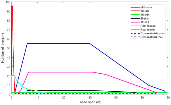
Figure 1.
Distribution of section’s layup layers along the blade radial coordinate.
2.3. Cost of Energy (COE) Model
The study [17] has shown the design objective of maximizing annual energy production or using sequential aerodynamic and structural optimization to be significantly suboptimal compared to the aero-structural integrated methods. For variable rotor diameter and hub height, the optimal rotor diameter may be misleading because the tower mass dominates the total mass of turbine. Thus, minimizing COE is a much better metric for the full-scale wind turbine optimization objective than minimizing the ratio of turbine mass to annual energy production. The main objective is to minimize the COE of a wind turbine used in low wind speed areas. Following the study [15], COE is calculated as:
where FCR is the fixed charge rate, ICC is the initial capital cost, AOE is the annual operating expenses, and AEP is annual energy production.
As wind turbines become more sophisticated in terms of aerodynamic shape and structural configuration with increasing size, the design of each wind turbine component is not always clear. The COE model is used to assess the true impact of the technical change and various designs. The FCR, ICC and AOE are obtained from the National Renewable Energy Laboratory (NREL) wind turbine design cost and scaling model [15]. The BEM code and the Weibull probability distribution with annual average wind speed of 6 m/s at hub height are used to calculate AEP. The blade stiffness and mass distributions are computed by the classical laminate theory code named PreComp [18]. The total cost of a wind turbine is defined by adding the value of the initial capital cost multiplied by the fixed charge rate to the annual operating expenses. The fixed charge rate is the annual amount per dollar of initial capital cost used to cover the capital cost and other fixed charges. The FCR value is set to 0.1158 per year as suggested in reference [15].
3. Theoretical Models and Verifications
3.1. Aerodynamic Model
In this work, the combination of blade element theory and momentum theory is used to estimate the aerodynamic performance and calculate the AEP. The blade element theory aims to calculate the aerodynamic force acting on each blade element. The blade momentum theory refers to analysis of both axial and tangential induced velocity by introducing axial and angular induction factors. The induced velocity in each blade section influences the angle of attack of the airfoil and therefore affects the loads acting on the blade sections. With an iterative procedure, BEM theory provides a method to calculate the aerodynamic loads on each blade element. For a rotor with a finite number of blades, the vortex system in the wake is different from that of a rotor with an infinite number of blades [19]. By introducing the Prandtl’s tip loss factor, the BEM theory can simulate a wind turbine rotor with a finite blade number.
The aerodynamic performance of the total wind turbine blade can be obtained from each blade section. Thus, it is necessary to acquire the lift and drag coefficient of the adopted airfoil. However, the experimental polar of airfoils are not often available. In this work, RFoil [20] is used to estimate the aerodynamic characteristics of the airfoil. The RFoil code is an improved version of XFoil [21] and has many advantages such as better corrections after stall.
The annual average wind speed is the main source of wind power. Due to the friction of the plants and constructions, better wind resources are located at higher heights. The friction coefficient n could affect the average wind speed at hub height, and the different average wind speed at hub height could have an impact on the AEP of wind turbines. In this work, the friction coefficient is set as 0.23 which corresponds to the roughness of the countryside. The wind speed is varied depending on the hub height according to the following equation:
where Vhub is the wind speed at the hub; Hhub is the hub height; Vref is the reference wind speed at the reference height; Href is the reference height; and n is the friction coefficient and set as 0.23 for low wind speed condition.
3.2. Blade Element Momentum (BEM) Code Validation
In this work, a commercial wind turbine for Class III with blade length 59.8 m and 2.1 MW of rated power is used as a reference. The aerodynamic performance of the blade is calculated by considering a tip speed ratio of 10.6 with a range of wind velocities between 3 m/s and 20 m/s. Air density is set to 1.225 kg/m3 and the cone and tilt angle of the wind turbine are set to zero degrees. The RFoil is used to calculate the aerodynamic characteristics of Delft University (DU) series airfoils for a specific Reynolds number according to their locations. The power coefficient and the power curves calculated by BEM code are implemented in MATLAB software (MATLAB 2014b; The MathWorks Inc.: Natick, MA, USA, 2014). In order to validate the BEM code, the aerodynamic performance data from the wind turbine manufacturer, based on simulations by WINDnovation Engineering Solutions GmbH, are compared with the BEM code. The numerical simulations and the manufacturer’s data show an excellent agreement as shown in Figure 2. The power curve calculated by BEM code shows that the rated power is achieved with wind velocity of 9 m/s. Therefore, the aerodynamic performance prediction of the wind turbine blade calculated by BEM code for this study can be considered acceptable.
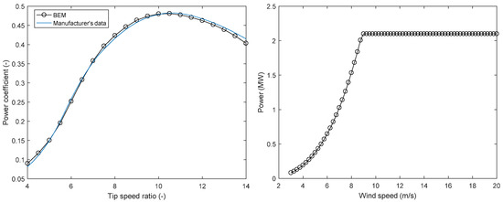
Figure 2.
Comparison between the power coefficient and power curves obtained by blade element momentum (BEM) code and wind turbine manufacturer’s data.
3.3. Structural Model
The structural performance can be represented by the cross-sectional composite properties of each blade section. In order to evaluate the cross-sectional composite properties of the blade section, classical lamination theory [22] is applied during the optimization procedure. For the laminated plates, the CLT model is an extension of classical plate theory [23] which has improvements in reasonable validation and computational efficiency. Thus, the CLT model can confirm the overall effective performance of composite laminated structure of wind turbine blade. Bir et al. [18] developed a FORTRAN code named PreComp (pre-processor for computing composite blade properties) to calculate the blade structural properties based on CLT. PreComp requires input files of the blade geometric shape, interior structural layout and materials properties. In addition, PreComp allows various internal geometry configurations and a general layup of composite laminates. The CLT model can transfer a complex three-dimensional problem into calculating two-dimensional blade section properties. In this paper, PreComp is applied to evaluate the structural properties of wind turbine blade sections. The structural parameters like blade geometry and layup schedule are set the same as the actual blade. After that, the stiffness and the mass per unit length distributions can be calculated. Figure 3 shows that the calculated stiffness values are in good agreement with the manufacturer’s data based on simulations by WINDnovation Engineering Solutions GmbH.
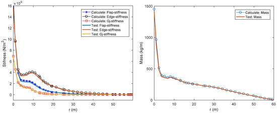
Figure 3.
Comparison between the stiffness and mass per unit length distributions obtained by CLT code and actual blade.
4. The Optimization Model
In general, according to the wind turbine blades used in Class I, the same turbine family used in Class III has a length of 130~140% [6]. When the length of the blades increases, the blade mass and tip deflections will also increase. For structural and aerodynamic performance, the fitness function f in this paper is to minimize the cost of energy:
4.1. Design Variables
The geometric shape of the blade can be generated by chord distribution, twist distribution and the airfoil series. Eight control points are used for the thickness distribution, and the upper and lower bounds of the control points are set with adequate space, as shown in Figure 4. Nine control points are used for the chord and twist distributions, as shown in Figure 5. The first control point of chord distributions is at the root, the third control point is at the maximum chord station, and the ninth control point is at the blade tip. The thickness distribution is defined with a 9th order Bezier curve, and the chord and twist distributions are defined with a 10th order Bezier curve. For large scale wind turbine, a lower tip speed ratio would result in less efficient aerodynamic performance but lower cost of fabrication because of less aerodynamic loads by lower blade centrifugal stresses. The lower tip speed ratio can also reduce the tower cost because of the lower aerodynamic loads from the rotor. Thus, the tip speed ratio is set as a design variable in the design process.
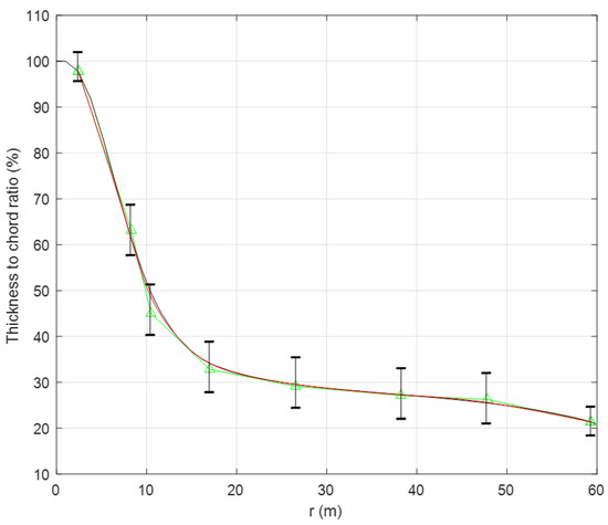
Figure 4.
Thickness distribution of the blade.
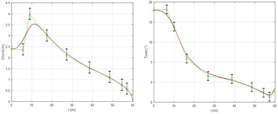
Figure 5.
Chord and twist distributions of the blade.
The typical airfoil and its internal structural configuration of a typical modern wind turbine blade are shown in Figure 6 (c is the chord length). The internal structure mainly consists of spar cap and shear webs. The spar caps at the maximum thickness resist the flap-wise loads and the two shear webs resist the torsional loads. In this work, the maximum thicknesses of the spar cap and trailing edge reinforcement are the design variables for the blade layup schedule which are shown in Figure 7. The shear webs distributions are also considered in the structural optimization design. The locations of each web at blade root and tip are set as design variables.
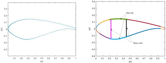
Figure 6.
Typical structural parameters for section of the blade.
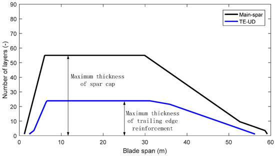
Figure 7.
Design variables for spar cap and trailing edge reinforcement.
Figure 8 presents the schematic of the tower structure. With increasing tower height, the optimization design needs to trade off between the energy production and the cost of the structure. The wind turbines used in low wind speed areas always have higher hub height to obtain better wind sources than those used in high wind speed areas. The tower heights are always much greater than 80 m in low wind speed areas. Thus, the relationship of the tower mass and cost scaling are not efficient [15]. Therefore, an actual 2.1 MW commercial tower is used in an optimization process instead of using an empirical equation for the tower cost. Foundations were scaled as a function of hub height and rotor swept area, which is directly proportional to the tower overturning moment. The top and base diameters of the tower and their thickness are taken as design variables. The variations of diameters and thickness across the length of the tower are assumed as a linear distribution.

Figure 8.
Schematic of tower structure.
4.2. Design Constraints
A real wind turbine must be designed to meet plenty of constraints. For the aerodynamic design, the blade root bending moment is always [14,17] set as a constraint for the blade design individually, but it is unnecessary for whole wind turbine design. The full scale design considers the whole structural stability instead of local aerodynamic performance. In this work, representative cases are used to meet the structural constraints. The wind turbine needs to meet the criteria of the structural strength in the process of operation. The ultimate strength analysis of the blade and the tower is performed in an extreme load condition. The 50-year extreme wind condition is defined as Ve50 = 1.4Vref (Vref = 37.5 m/s for Class III wind resources).
4.2.1. Blade Design Constraints
In order to verify the structural stability of the blade, the structural design needs to withstand the extreme wind condition. Some representative sections are selected to calculate the strain and verify the strength. These sections are at the blade root and the airfoils’ locations along the blade span on both the upper and lower surfaces. A maximum strain condition is used as [17]:
where the ε50 is the strain at 50-year extreme wind condition, the εult is ultimate strain, the partial safety for loads (γf) is set as 1.35 and the partial safety factor for materials (γm) is set as 1.1 according to IEC 61400-1 requirement. The representative numbers of ultimate strain is set as 0.03. The maximum tip deflection of the blade under extreme loading is added to ensure adequate stiffness. In this work, considering the blade length is set as a variable, the maximum tip deflections with various blade lengths are set as:
where δopt is the maximum tip deflection of the optimal blade, the δorig is the maximum tip deflection of the original blade, Ropt is the length of the optimal blade, and Rorig is the length of the original blade.
4.2.2. Tower Design Constraints
The tower is the main support component of the wind turbine to withstand the aerodynamic loads and the total mass of the other components. The structural properties of the tower have a significant impact on the total cost of the wind turbine. An efficient, safe and economic design of the tower that meets all the design criteria is needed to minimize the total wind turbine cost. The loads acting on the tower mainly come from the aerodynamic loads on the rotor, and the wind loads on tower itself are also considered. The thrust force on the rotor is transferred to the tower top and causes tower deformation. In order to ensure structural stability and avoid large deformation, the maximum deformation at the top of the tower should not exceed the allowable deformation:
The dallow is the allowable deformation and it can be determined according to the reference [18]. In order to ensure the tower has an adequate structural performance during optimization process, the allowable deformation is set as [8]:
where Hopt is the height of the optimal tower, Horig is the height of the original tower, and dorig is the top deformation of the original tower.
In order to verify the structural stability of the tower, the structural design needs to withstand thrust from the wind turbine rotor. For a tapered tower, the location of the critical stress is at about the middle of the tower (the bending moment is largest at the base, but so is the moment of inertia) [17]. In this work, we assumed that the critical location was at the middle of the tower. Then, the stress at that location can be calculated as:
where σcr is the critical stress, mRNA is the mass of rotor and nacelle assembly, mtower_mid_up is the tower mass above the middle of the tower, Amid is the area of the middle of the tower, T is the rotor thrust, H is the tower height, and Imid is the area moment of inertia at the middle of the tower.
The stress σcr generated by the loads cannot exceed the allowable stress:
The σallow is the allowable stress and the value of it is given by:
where σys is the yield strength and γtm is the material safety factor of the steel. The yield strength of the steel is 345 MPa for the wall thickness between 16 mm and 40 mm. The material safety factor is set as 1.1 according to IEC 61400-1.
4.3. The Optimization Algorithm
The purpose of this paper is to investigate the cost of energy for a low wind speed turbine considering rotor diameter and hub height as variables. The optimization progress aims to find the ideal blade shape parameters such as chord, twist, thickness distributions and the blade length, and to find the structural performance like webs locations, layer-up distributions and the tower parameters (height, taper and wall thickness distributions). The design process interfaces the particle swarm optimization (PSO) algorithm, BEM code, PreComp code and the COE model. There are three modules integrated in the PSO algorithm by using MATLAB: (1) the aerodynamic performance analysis based on BEM theory; (2) the structural performance analysis by PreComp code; and (3) the design constraints by beam theory and strength theory. The basic parameters of the PSO algorithm are defined as: the population size (p = 80), maximum number of generations (g = 200), learning factors (c1 = c2 = 0.5), variable dimensions (n = naerodynamic + nstructural = 36), and the inertia factor (0.85).
Figure 9 shows the flowchart of the optimization process. The aerodynamic and structural variables for blades and the tower are randomly generated as the initial population. The aerodynamic variables are used to control the blade shape, the structural variables are used to control the webs locations and number of layers along the blade, and the variables for the tower are used to control the tower height and structural parameters. BEM theory is applied to calculate the annual energy production and the aerodynamic loads which will cause the blade deflection and tower deformation. Moreover, the PreComp code is adopted to evaluate the mass and stiffness of the blade sections. The requisite parameters are airfoil profiles, chord length and twist angle, materials characteristics, internal configurations of blade sections and the lay-up distributions. When a wind turbine is acquired during the optimization process, the blade and tower constraints are validated. By analyzing the results, a new wind turbine design with minimum COE will be outputted.
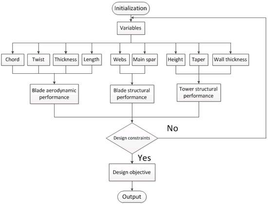
Figure 9.
Flowchart of the optimization process.
5. Results and Discussion
In this section, the results are presented and analyzed. Most of the components are a function of the parameters such as rotor diameter and rated power, as shown in Figure 10. The relationship shows that the rated power also has a strong impact on COE. Thus, the optimization procedures considering rated power or not (set as 2.1 MW) are shown.
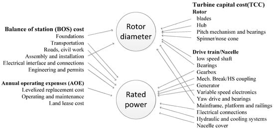
Figure 10.
Relationship of rotor diameter and rated power to the components of wind turbine.
After the design procedure is finished, the iterative course of the optimization process by considering rated power is shown in Figure 11. It can be seen that the optimal results converge when the number of iteration steps reach 80.
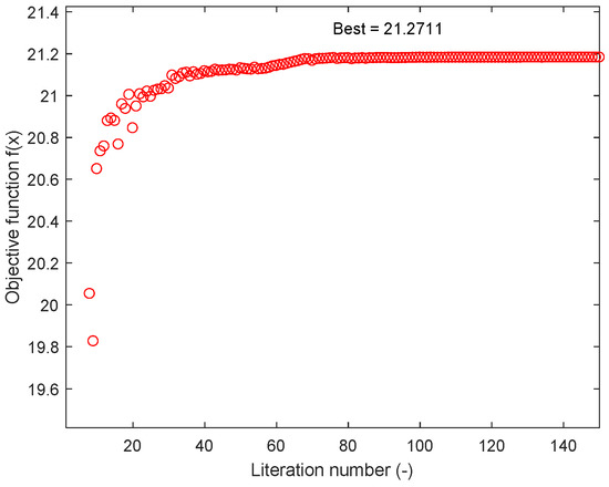
Figure 11.
The iterative course for the optimization process considering rated power.
5.1. Blade Optimization Results
The chord and twist distributions of the new blade acquired by the optimization process are shown in Figure 12. The optimization process considering rated power is referred to as “CRP” for brevity. The chord distributions of the new blades decrease slightly, and the optimal chord distribution considering rated power is less than that without. The reason is that the optimal blade length acquired from the design considering rated power is less than that of the original blade and the optimal one without considering the rated power. Due to differences in aerodynamic loads, the structural requirements of the shorter blade are less than those of the longer one. The reduction of the chord distribution can result in a lighter blade mass and a lower thrust at the blade root. The twist distributions of the new blade are almost the same as the original one, the main reason is that the airfoil series adopted in this work are fixed, and the aerodynamic characteristics of the airfoils are the same. Another reason is that the twist distribution does not have a significant impact on COE compared to the chord distribution. The thickness distributions of the new blade acquired by the optimization process are shown in Figure 13. The main reason why the thickness distributions do not change much could be that the lengths of the optimal blades do not change significantly. In addition, when the thickness reduces, the stiffness would reduce too. In order to meet the design constraints, the thickness distributions do not change much.
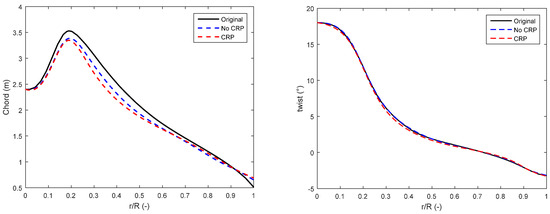
Figure 12.
The comparison of chord and twist distributions between the optimal blades and the original one.
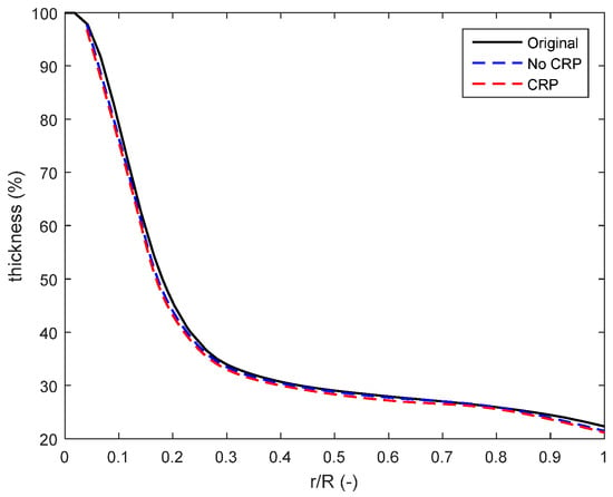
Figure 13.
The comparison of thickness distributions between the optimal blades and the original one.
The Weibull distributions with annual average wind speed according to corresponding hub height (95, 117.2, 119.8 m) are shown in Figure 14. The annual average wind speed of 6 m/s of Weibull scaling factor (A = 6.8) and form factor (k = 1.91) determined from meteorological data of inland China is set as the annual average wind speed at hub height of 95 m. The annual average wind speed at optimal hub heights considering rated power (119.8 m) or not (117.2 m) are 6.3288 m/s and 6.2969 m/s, respectively. The Weibull form factor is assumed to be fixed as 1.91. The Weibull distributions show that the optimal hub heights have more probability with higher wind speed.
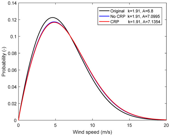
Figure 14.
Weibull probability distribution of wind speed (6 m/s, 6.2969 m/s and 6.3288 m/s).
Figure 15 shows the comparison of the annual energy production between the optimal blades and the original one. Due to the differences of the Weibull distribution of the average wind speed at the hub height, the shape curve of the energy production between the original wind turbine and the optimal ones is not proportional. The energy production of the optimal wind turbine is slightly less than the original blade with a range of 3 m/s to about 8 m/s wind speed and is much higher from a speed of about 8 m/s to cut out speed (20 m/s). The results indicate that the AEP of the wind turbine (6.0921 GW) without considering rated power is higher than the original one (5.783 GW), but the one considering rated power (5.8364 GW) is similar to the original one.
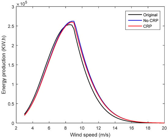
Figure 15.
The comparison of the annual energy production (AEP) between the optimal blades and the original one.
Figure 16 shows that the comparison of the power curves between the optimal blades and the original one. The results indicate that the new blade without considering the design value of rated power as the variable can achieve rated power of 2.1 MW at the rated wind speed of about 9.2 m/s. The design value of rated power of the optimal wind turbine by considering rated power as the variable is 1.9 MW, and can achieve rated power at the rated wind speed of about 9.1 m/s. Both designs need higher wind speeds to achieve the rated power compared to the rated wind speed of 9 m/s of the original wind turbine. The main reason is that the lengths of the new blades are shorter than those of the original. This will result in less capacity in energy capture.
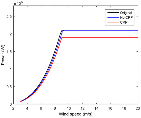
Figure 16.
The comparison of the power curves between the optimal blades and the original one.
Figure 17 shows the distributions for spar caps and trailing edge reinforcement. The thickness of the spar caps and trailing edge reinforcement has increased compared to that of the baseline blade. The main reason for this is that the optimal blade needs to meet the structural constraints due to the large decrease of chord length distributions.
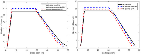
Figure 17.
Structural thickness distributions of the baseline and the optimized blades.
The detailed results of the design objectives of minimizing the cost of energy are shown in Table 5. The longest blade is the original one and the shortest blade is the optimization considering rated power. The optimal wind turbines have COE of 0.0478 $/kWh and 0.047 $/kWh (CRP), compared to that of 0.057 $/kWh of the initial one.

Table 5.
Optimization design results of the blade.
5.2. Tower Optimization Results
The distributions of outer diameters and wall thicknesses along the tower height are shown in Figure 18. Both of the optimal towers have larger outer diameter and thickness distributions to meet the structural constraints. Table 6 shows the comparison of the optimization results between the optimal towers and the original one. Both of the optimal towers are taller than the original one. With the increase of tower height, the annual average wind speed also increases. Hence, the rotor can capture more wind power to improve the AEP. However, with the increase of wind speed, the aerodynamic loads acting on the rotor and hence the thrust will also increase. The tower’s structural design needs to consider that an increase in thrust on the tower top will cause a larger deformation. The tower mass increases when the tower height increases. Compared to the original tower, the two optimal towers have an increase in mass of about 43.65% and 42.49% (CRP). The main reason is that the tower height with 118m and 120m has higher annual average wind speed, and the greater rotor thrust requires a better structural performance with thicker walls. The height of the optimal tower considering rated power is higher but its mass is less than the one without considering rated power. The main reason for this is that the wind turbine with longer blades has larger thrust acting on the tower top.
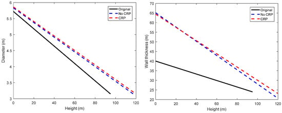
Figure 18.
Tower outer diameter and wall thickness distributions of the baseline and the optimized towers.

Table 6.
Optimization design results of the tower.
Table 7 shows the costs of rotor, tower, and foundation in the cases of the original design, the optimal design (without CRP) and the optimal design (with CRP). The rotor costs of the optimal wind turbines are reduced compared with that of the original one. The main reason is that the optimal blades have a shorter length and lighter blade mass. The tower costs of the optimal wind turbines are increased compared with the original one due to the higher height and thicker wall distributions. Because of the shorter blade length and significant decrease in chord length distributions, the rotor thrust of the optimal wind turbine is less than that of the original one. Thus, the foundation costs do not change much, although the tower of the optimal wind turbine is higher than that of the original one.

Table 7.
Costs of rotor, tower, and foundation.
6. Conclusions
In this work, a wind turbine optimization for low wind speed areas is performed to investigate the relationship between rotor diameter and hub height. With the characteristic of high aspect ratio of the blade used in regions of wind Class III, the deflection of the longer blade is larger than the blade used in regions of wind Class I. According to this characteristic, the design needs to pay more attention to structural performance. In order to minimize the COE, the yield by increasing rotor diameter is less efficient than that by adding hub height, despite the fact that there is a large initial capital cost for the tower.
The AEP is evaluated by the determination of the electric energy generation as a function of average annual wind speed. The capacity of power generation is related to the aerodynamic performance of the rotor which is calculated by BEM theory and the annual average wind speed based on the hub height. The structural performance of the blade is calculated by the CLT method and the blade stability is estimated by the imposed constraints. The hub height has an impact on the annual average wind speed as well as AEP. A wind turbine with higher hub height has better wind resources but needs more efficient structural design. Although the larger rotor diameter and higher tower can generally produce more energy, the capital cost for that is not worthwhile. In low wind speed areas, it is not suitable to increase the rotor diameter alone and a solution needs to combine the whole system. For the purpose of minimizing the COE, increasing the rotor diameter for more annual energy production is not sufficient to outweigh increasing the cost of the wind turbine. The rated power is set as a variable to investigate its impact on COE. The results show that the design value of the rated power has a strong impact on COE.
Author Contributions
J.C. conceived and designed the project; H.Y. performed the computations and analyzed the results; H.Y., J.C. and X.P. wrote the paper.
Funding
This work is supported by National Natural Science Foundation of China (No.: 51175526).
Conflicts of Interest
The authors declare no conflict of interest.
References
- International Electrotechnical Commission. IEC 61400-1: Wind Turbines Part 1: Design Requirements; International Electrotechnical Commission: Geneva, Switzerland, 2005. [Google Scholar]
- Cristina, V.H.; Thomas, T.; Anahí, V.P. JRC Wind Energy Status Report—2016 Edition; Market, Technology and Regulatory Aspects of Wind Energy; Publications Office of the European Union: Luxembourg, 2017; pp. 10–11. [Google Scholar]
- Wichser, C.; Klink, K. Low wind speed turbines and wind power potential in Minnesota, USA. Renew. Energy 2008, 33, 1749–1758. [Google Scholar] [CrossRef]
- Wang, X.; Shen, W.-Z.; Zhu, W.-J.; Sørensen, J.-N.; Jin, C. Shape optimization of wind turbine blades. Wind Energy 2009, 12, 781–803. [Google Scholar]
- Lee, J.; Lee, K.; Kim, B. Aerodynamic optimal blade design and performance analysis of 3 MW wind turbine blade with AEP enhancement for low-wind-speed-sites. J. Renew. Sustain. Energy 2016, 8, 1–12. [Google Scholar] [CrossRef]
- Barnes, R.H.; Morozov, E.V.; Shankar, K. Improved methodology for design of low wind speed specific wind turbine blades. Compos. Struct. 2015, 119, 677–684. [Google Scholar] [CrossRef]
- Barnes, R.H.; Morozov, E.V. Structural optimisation of composite wind turbine blade structures with variations of internal geometry configuration. Compos. Struct. 2016, 152, 158–167. [Google Scholar] [CrossRef]
- Nicholson, J.C. Design of Wind Turbine Tower and Foundation Systems: Optimization Approach. Master’s Thesis, University of Iowa, Iowa City, IA, USA, 2011. [Google Scholar]
- Wang, L.; Kolios, A.; Luengo, M.M. Structural optimisation of wind turbine towers based on finite element analysis and genetic algorithm. Wind Energy Sci. Discuss. 2016. [Google Scholar] [CrossRef]
- Wright, A.K.; Wood, D.H. The starting and low wind speed behaviour of a small horizontal axis wind turbine. J. Wind Eng. Ind. Aerod. 2004, 92, 1265–1279. [Google Scholar] [CrossRef]
- Pourrajabian, A.; Ebrahimi, R.; Mirzaei, M. Applying micro scales of horizontal axis wind turbines for operation in low wind speed regions. Energy Convers. Manag. 2014, 87, 119–127. [Google Scholar] [CrossRef]
- Singh, R.K.; Ahmed, M.R. Blade design and performance testing of a small wind turbine rotor for low wind speed applications. Renew. Energy 2013, 50, 812–819. [Google Scholar] [CrossRef]
- Salih, N.A.; Mohammed, A.H.; Talha, A.; Kamel, A.K. Experimental and theoretical investigation of micro wind turbine for low wind speed regions. Renew. Energy 2018, 116, 215–223. [Google Scholar]
- Maki, K.; Sbragio, R.; Vlahopoulos, N. System design of a wind turbine using a multi-level optimization approach. Renew. Energy 2012, 43, 101–110. [Google Scholar] [CrossRef]
- Fingerish, L.; Hand, M.; Laxson, A. Wind Turbine Design Cost and Scaling Model; Technical Report; National Renewable Energy Laboratory: Golden, CO, USA, 2006.
- Bortolotti, P.; Bottasso, C.L.; Croce, A. Combined preliminary–detailed design of wind turbines. Wind Energy Sci. 2016, 1, 71–88. [Google Scholar] [CrossRef]
- Ning, A.; Damiani, R.; Moriarty, P.J. Objectives and constraints for wind turbine optimization. J. Sol. Energy Eng. 2014, 136, 041010. [Google Scholar] [CrossRef]
- Bir, G.S. User’s Guide to PreComp: Pre-Processor for Computing Composite Blade Properties; National Renewable Energy Laboratory: Golden, CO, USA, 2005.
- Hansen, M.O.L. Aerodynamics of Wind Turbines, 2nd ed.; Earthscan: Abingdon, UK, 2008. [Google Scholar]
- Timmer, W.A.; van Rooij, P.R.J.O.M. Summary of the Delft University wind turbine dedicated airfoils. J. Sol. Energy Eng. 2003, 125, 48–96. [Google Scholar] [CrossRef]
- Drela, M. XFoil: An Analysis and Design System for Low Reynolds Number Airfoils; Technical Report; MIT Dept. of Aeronautics and Astronautics: Cambridge, MA, USA, 1989. [Google Scholar]
- Reddy, J.N. Mechanics of Laminated Composite Plates and Shells: Theory and Analysis; CRC: New York, NY, USA, 2003. [Google Scholar]
- Timoshenko, S.; Woinowsky-Krieger, S.; Woinowsky, S. Theory of Plates and Shells; McGraw-Hill: New York, NY, USA, 1959. [Google Scholar]
© 2018 by the authors. Licensee MDPI, Basel, Switzerland. This article is an open access article distributed under the terms and conditions of the Creative Commons Attribution (CC BY) license (http://creativecommons.org/licenses/by/4.0/).