The Influence of Valve-Pump Weight Ratios on the Dynamic Response of Leaking Valve-Pump Parallel Control Hydraulic Systems


Abstract
:1. Introduction
2. Methods
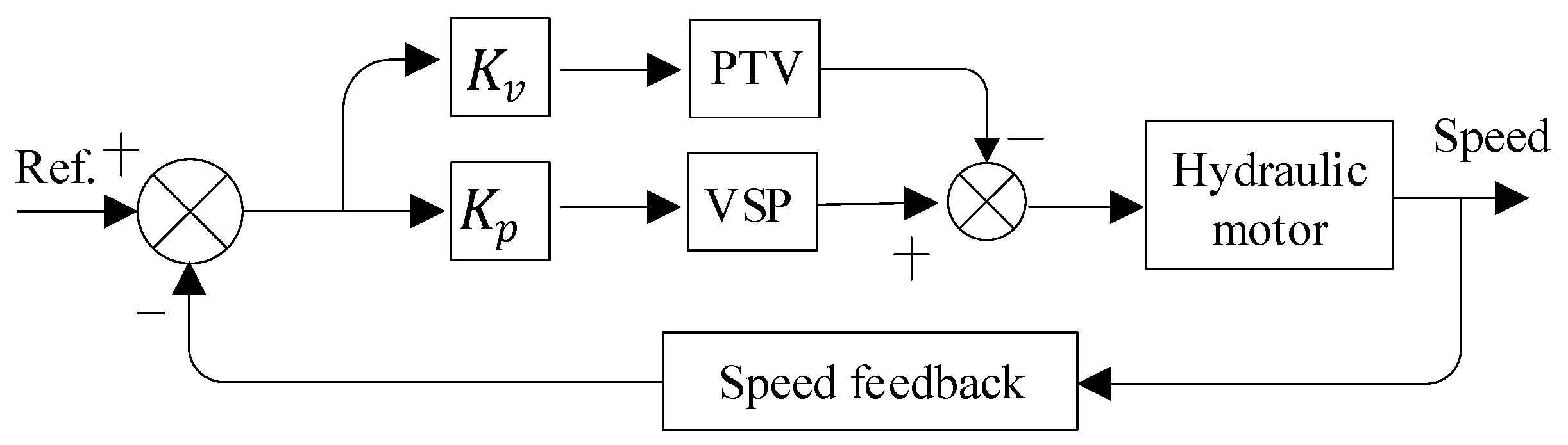
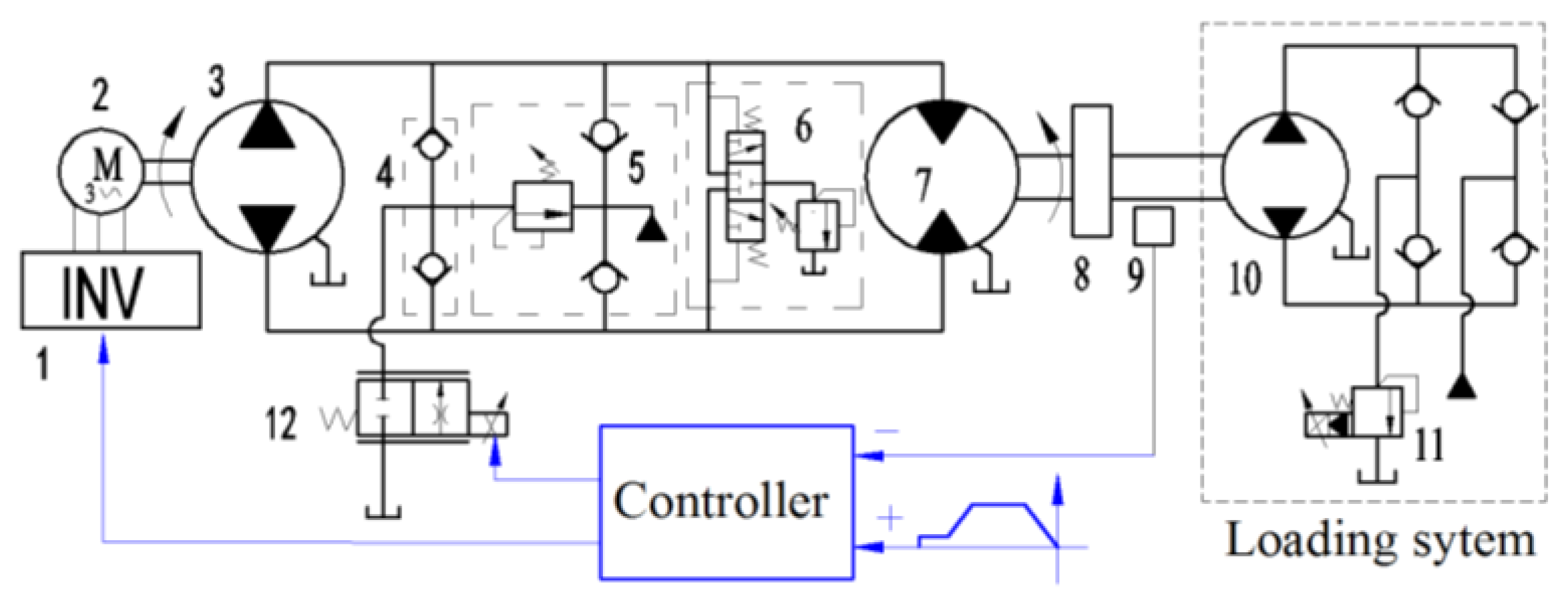
2.1. Principle of Proposed System
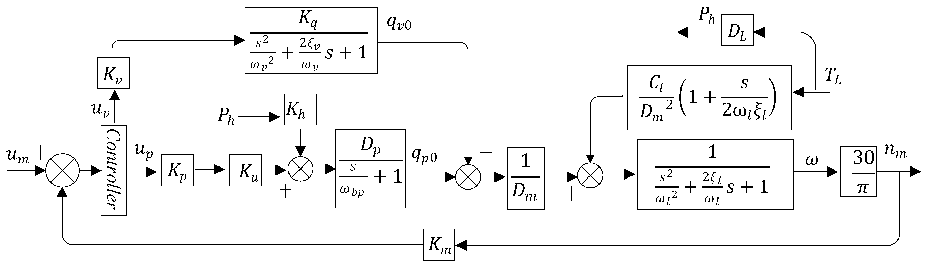
2.2. Mathematical Formulations
2.2.1. Inverter-Electric Motor Link
2.2.2. Parallel Valve Control Circuit
2.2.3. Valve-Pump Parallel Control Motor Link
2.2.4. Total System Mathematical Model
2.3. System Parameter Analysis
3. Case Studies
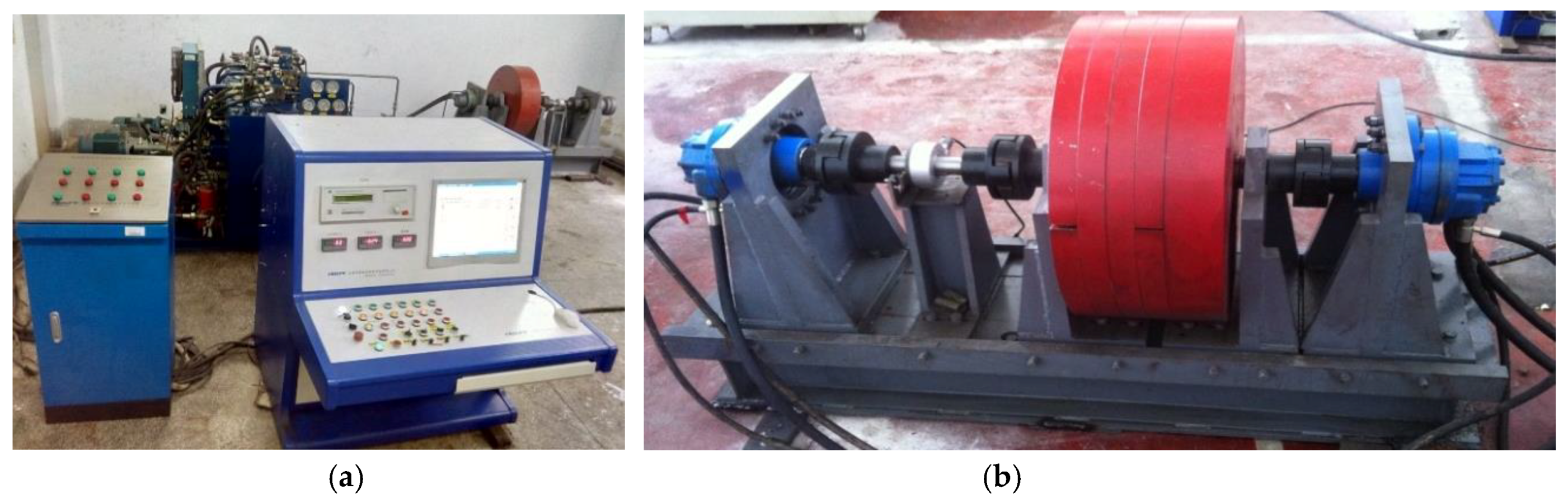
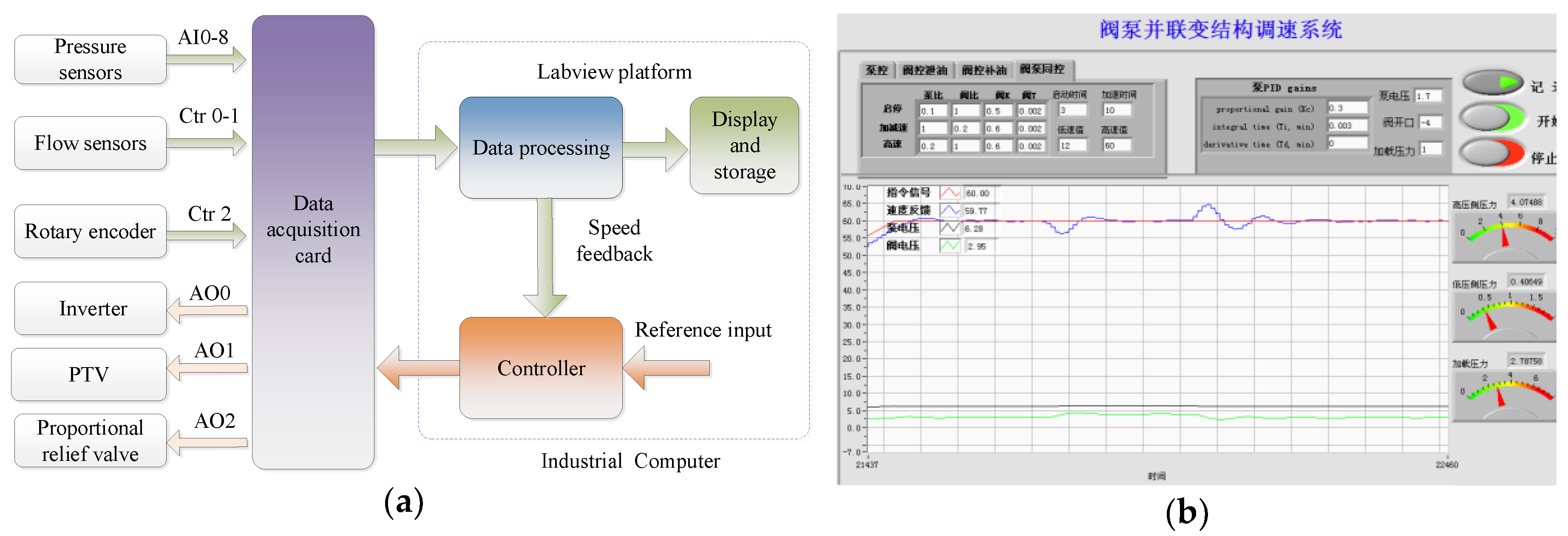
3.1. Experiment
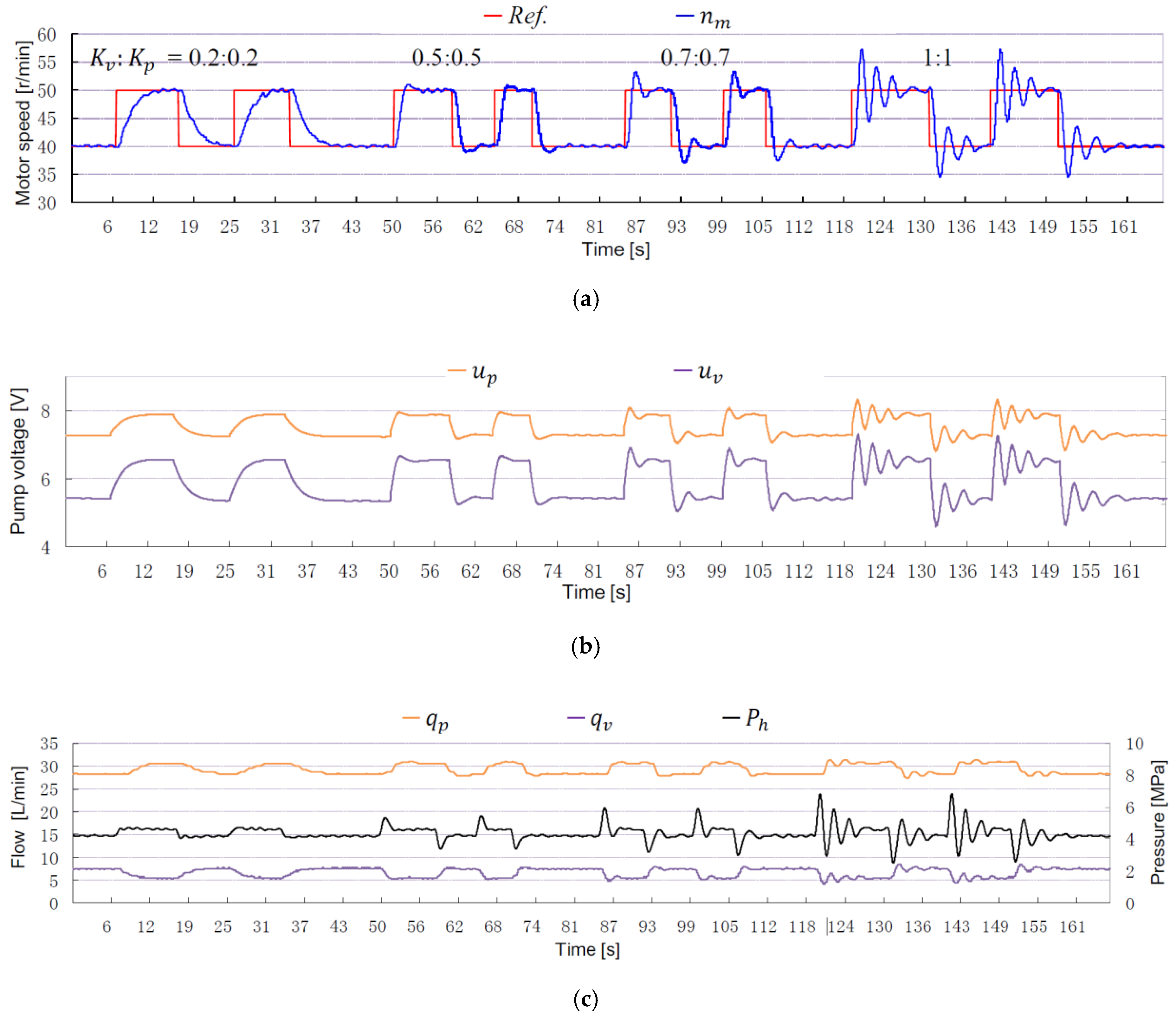
3.2. Results and Discussion
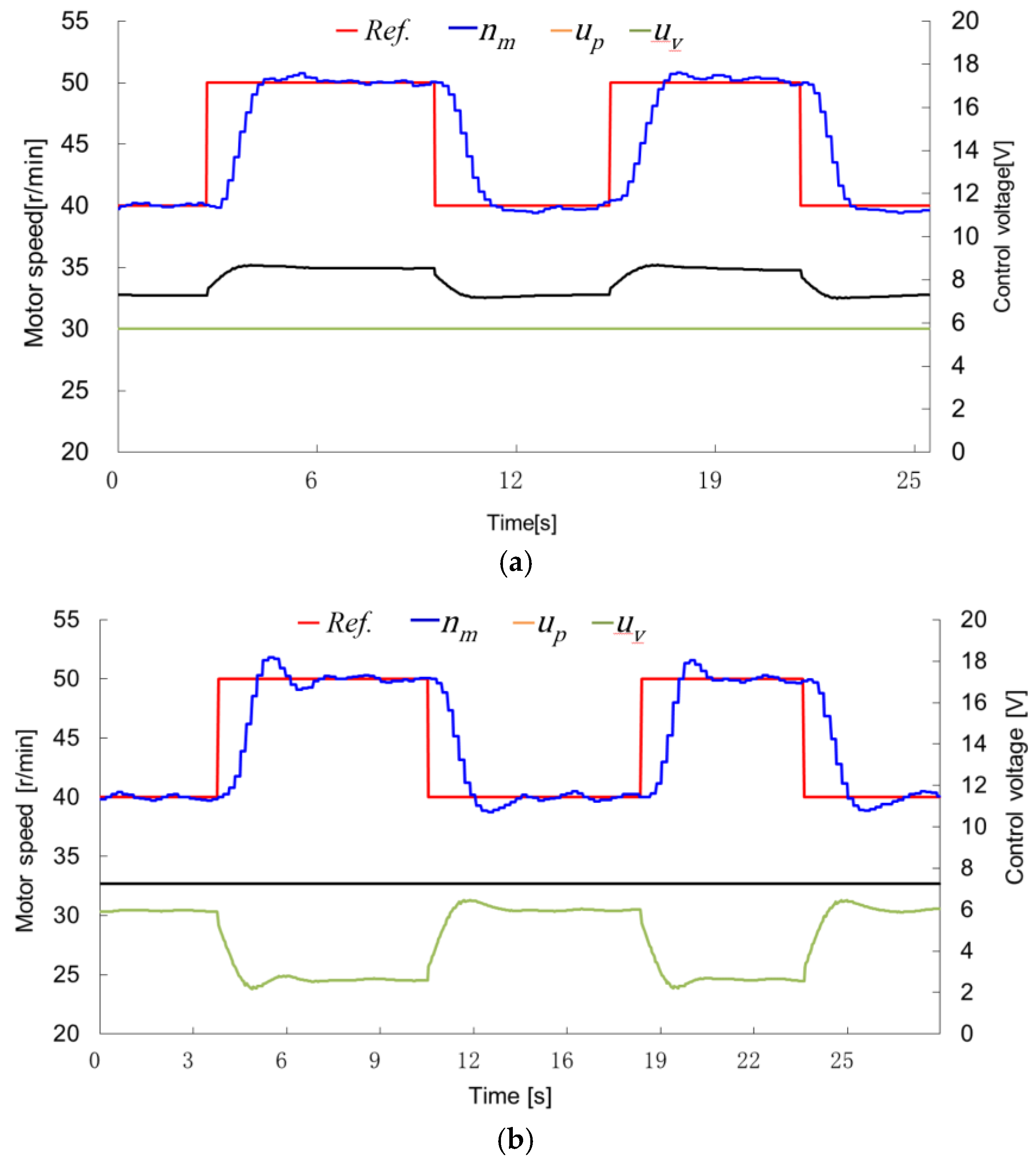
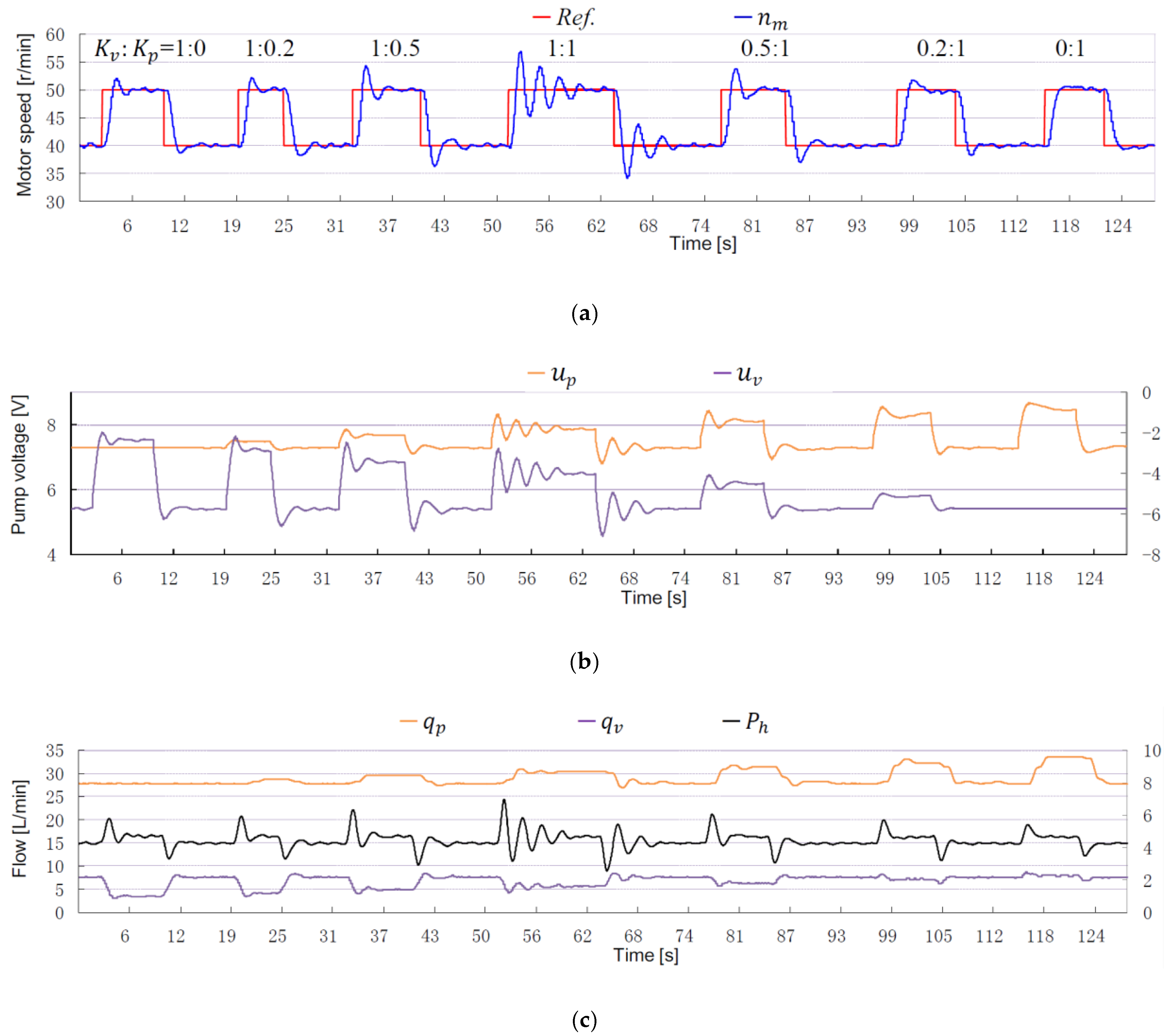
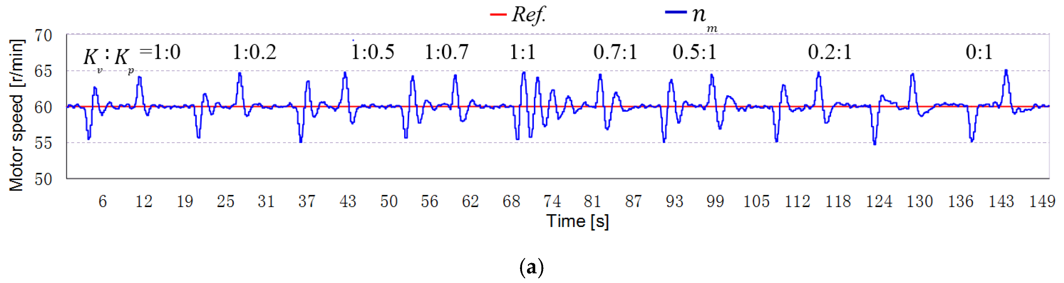
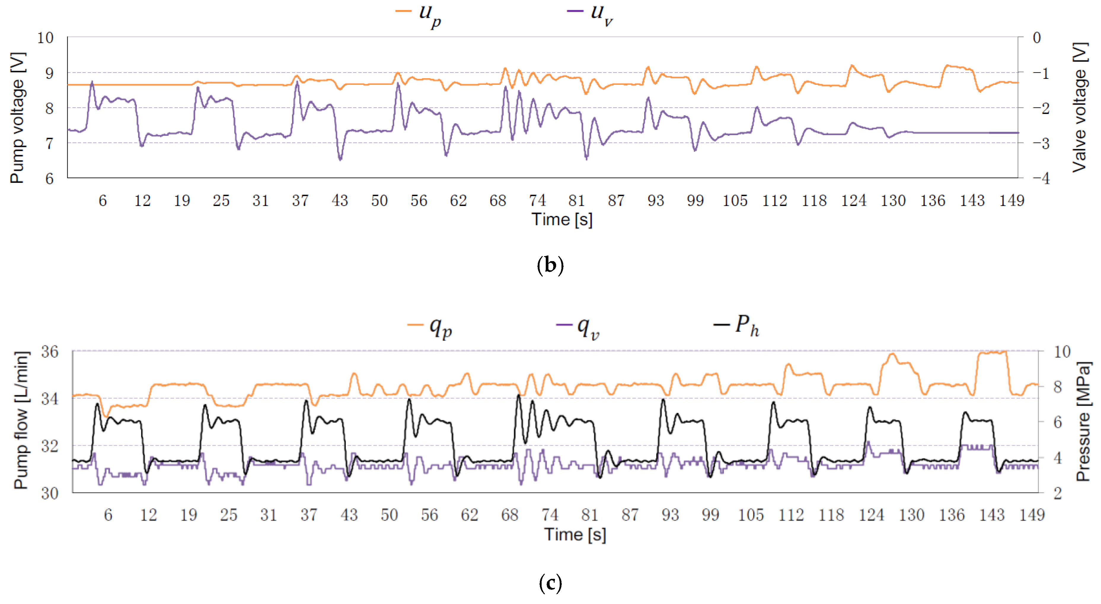
3.2.1. Step Responses to Reference Inputs
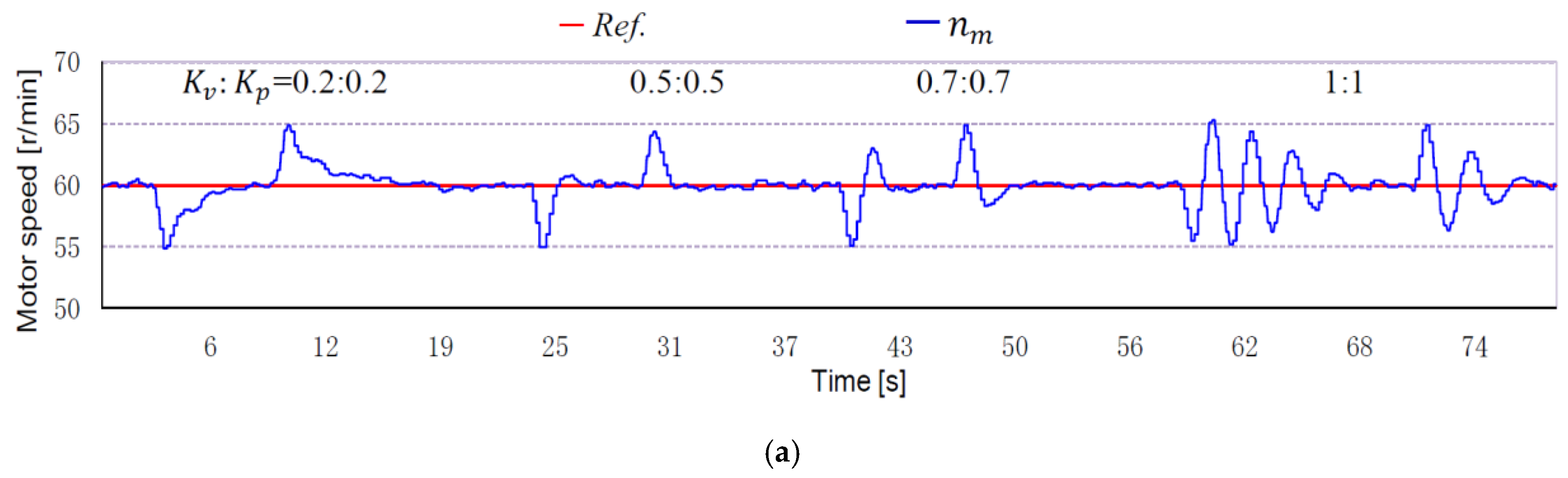
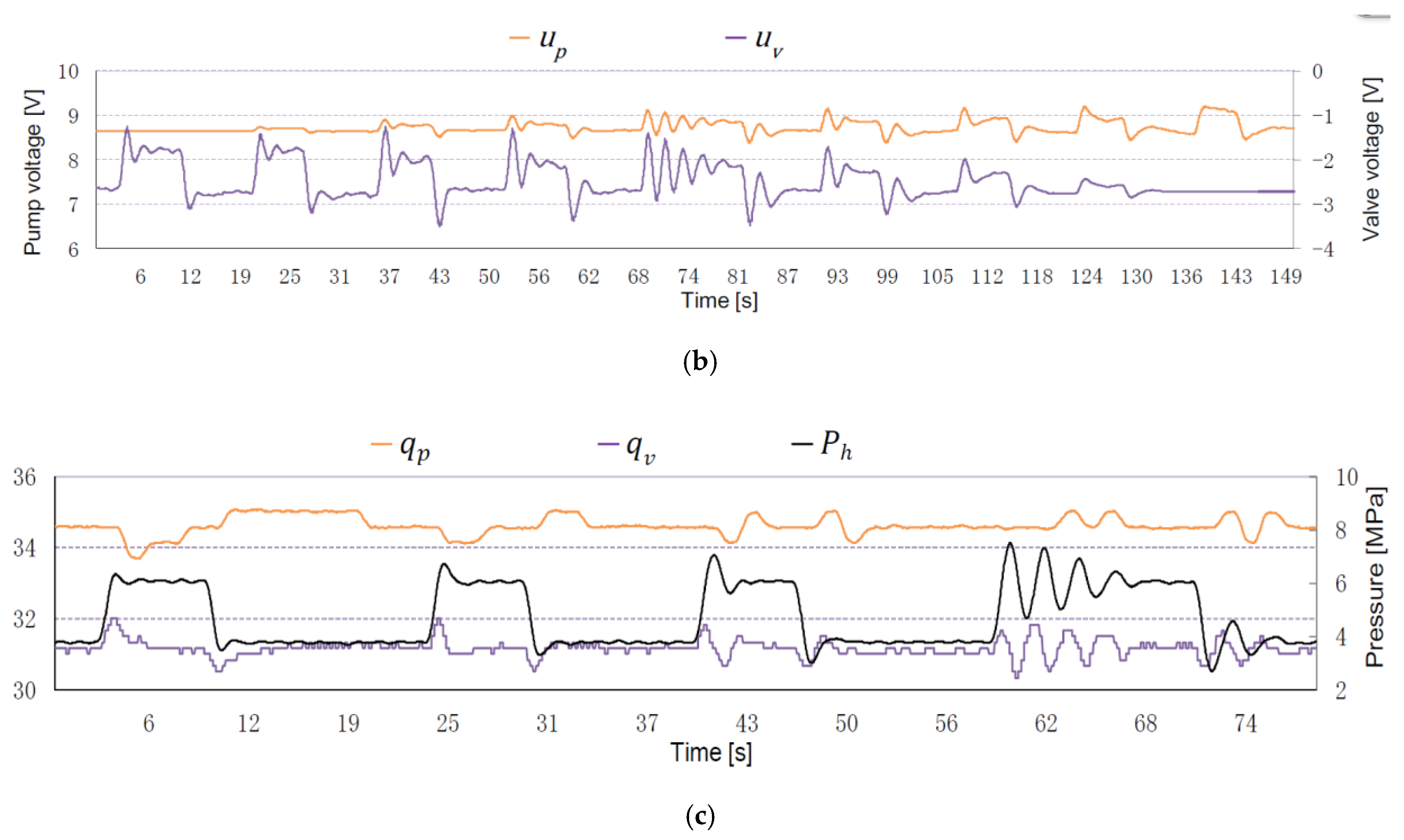
3.2.2. Step Responses to Loads
4. Conclusions
Author Contributions
Funding
Conflicts of Interest
Nomenclatures Index
| LPVC | leaking valve-pump parallel control |
| VSPC | variable speed pump control |
| PTV | proportional throttle valve |
| VSP | variable speed pump |
| valve-pump weighting ratio, | |
| weighting factor of the valve control link | |
| weighting factor of the pump control link | |
| flow gain of PTV | |
| pressure- flow coefficient of PTV | |
| valve control flow | |
| pump control flow | |
| total leakage coefficient of the LVPC system | |
| damping ratio of the LVPC system | |
| hydraulic natural frequency of the LVPC system | |
| total leakage coefficient of the VSPC system | |
| damping ratio of the VSPC system | |
| hydraulic natural frequency of the VSPC system |
References
- Manring, N.D. Hydraulic Control Systems; John Wiley & Sons: New York, NY, USA, 2005; ISBN 978-0-471-69311-6. [Google Scholar]
- Yin, X.X.; Lin, Y.G.; Li, W. Modeling and loading compensation of a rotary valve-controlled pitch system for wind turbines. J. Zhejiang Univ. Sci. A 2017, 18, 718–727. [Google Scholar] [CrossRef]
- Paloniitty, M.; Linjama, M. High-linear digital hydraulic valve control by an equal coded valve system and novel switching schemes. Proc. Inst. Civ. Eng. Mech. Eng. 2018, 232, 258–269. [Google Scholar] [CrossRef]
- Yao, J.; Wang, P.; Cao, X.M.; Wang, Z. Independent volume-in and volume-out control of an open circuit pump-controlled asymmetric cylinder system. J. Zhejiang Univ. Sci. A 2018, 19, 203–210. [Google Scholar] [CrossRef]
- Busquets, E.; Ivantysynova, M. A multi-actuator displacement-controlled system with pump switching: a study of the architecture and actuator-level control. Trans. Jpn. Fluid Power Syst. Soc. 2015, 8, 66–75. [Google Scholar] [CrossRef]
- Yang, H.Y.; Yang, J.; Xu, B. Computational simulation and experimental research on speed control of VVVF hydraulic elevator. Control Eng. Pract. 2004, 12, 563–568. [Google Scholar]
- Yang, H.Y.; Geng, T.; Gong, G.F. Variable speed pump control system for driving cutter head of test shield tunnelling machine. J. Zhejiang Univ. (Eng. Sci.) 2010, 44, 373–378. [Google Scholar]
- Creaco, E. Exploring numerically the benefits of water discharge prediction for the remote RTC of WDNs. Water 2017, 9, 961. [Google Scholar] [CrossRef]
- Page, P.R.; Abu-Mahfouz, A.M.; Mothetha, L. Pressure management of water distribution systems via the remote real-time control of variable speed pumps. J. Water Resour. Plann. Manage 2017, 143, 04017045. [Google Scholar] [CrossRef]
- Ding, H.G.; Zhao, J.Y.; Li, G.Z. Analysis of valve-pump combined high power hydraulic speed regulation schemes. J. Chin. Coal Soc. 2013, 38, 1703–1709. [Google Scholar]
- Manasek, R. Simulation of an electro-hydraulic load sensing system with AC motor and frequency changer. In Proceedings of the 1st FPNI-PhD Symposium, Hamburg, Germany, 20–22 September 2000; pp. 314–324. [Google Scholar]
- Shen, H.K.; Jin, B.; Chen, Y. Research on variable speed electro-hydraulic control system based on energy regulating strategy. In Proceedings of the ASME International Mechanical Engineering Congress and Exposition, Chicago, IL, USA, 5–10 November 2006; pp. 230–236. [Google Scholar]
- Shen, H.K.; Jin, B.; Chen, Y. Variable speed hydraulic control system based on energy regulation strategy. Chin. J. Mech. Eng. 2009, 45, 210–213. [Google Scholar] [CrossRef]
- Cochoy, O.; Carl, U.; Thielecke, B.F. Integration and control of electromechanical and electrohydraulic actuators in a hybrid primary flight control architecture. In Proceedings of the International Conference on Recent Advances in Aerospace Actuation Systems and Components, Toulouse, France, 24–26 December 2007; pp. 1–8. [Google Scholar]
- Kang, R.J.; Jiao, Z.X.; Wang, S.P. Design and simulation of electro-hydrostatic actuator with a built-in power regulator. Chin. J. Aeronaut. 2009, 22, 700–706. [Google Scholar]
- Ding, H.G.; Zhao, J.Y. Dynamic characteristic analysis of replenishing/leaking parallel valve control systems. Automatika 2017, 58, 82–194. [Google Scholar] [CrossRef]
- Alessandro, R.; Salvatore, M.; Nicola, N. Modelling a variable displacement axial piston pump in a multi-body simulation environment. ASME J. Dyn. Syst. Meas. Contr. 2007, 129, 456–468. [Google Scholar]


| Components | Specification |
|---|---|
| Electric motor | power:7.5 Kw; rated speed:3000 r/min; control voltage: 0–10 V |
| Inverter | power:11 kW with vector control; frequency range:0.1–100 Hz; |
| Fixed pump | displacement:12.6 mL/r; speed range:500–3000 r/min |
| Hydraulic motor | speed range: 0–90 r/min; displacement:468 mL/r; rated pressure: 40 MPa |
| PTV | rate flow: 9 L/min at 1.5 MPa per notch; frequency: 60 Hz; damping ratio: 0.7 |
| Proportional relief valve | pressure rang: 0.7–31.5 MPa; rate flow:200 L/min |
| Rotary inertia | 72 kg⋅m2 |
| Control Mode | |||
|---|---|---|---|
| Pump control | 0.3 | 0.18 | 1.67 |
| Valve control | 0.6 | 0.12 | 5 |
© 2018 by the authors. Licensee MDPI, Basel, Switzerland. This article is an open access article distributed under the terms and conditions of the Creative Commons Attribution (CC BY) license (http://creativecommons.org/licenses/by/4.0/).
Share and Cite
Ding, H.; Zhao, J.; Cheng, G.; Wright, S.; Yao, Y. The Influence of Valve-Pump Weight Ratios on the Dynamic Response of Leaking Valve-Pump Parallel Control Hydraulic Systems. Appl. Sci. 2018, 8, 1201. https://doi.org/10.3390/app8071201
Ding H, Zhao J, Cheng G, Wright S, Yao Y. The Influence of Valve-Pump Weight Ratios on the Dynamic Response of Leaking Valve-Pump Parallel Control Hydraulic Systems. Applied Sciences. 2018; 8(7):1201. https://doi.org/10.3390/app8071201
Chicago/Turabian StyleDing, Haigang, Jiyun Zhao, Gang Cheng, Steve Wright, and Yufeng Yao. 2018. "The Influence of Valve-Pump Weight Ratios on the Dynamic Response of Leaking Valve-Pump Parallel Control Hydraulic Systems" Applied Sciences 8, no. 7: 1201. https://doi.org/10.3390/app8071201
APA StyleDing, H., Zhao, J., Cheng, G., Wright, S., & Yao, Y. (2018). The Influence of Valve-Pump Weight Ratios on the Dynamic Response of Leaking Valve-Pump Parallel Control Hydraulic Systems. Applied Sciences, 8(7), 1201. https://doi.org/10.3390/app8071201