1. Introduction
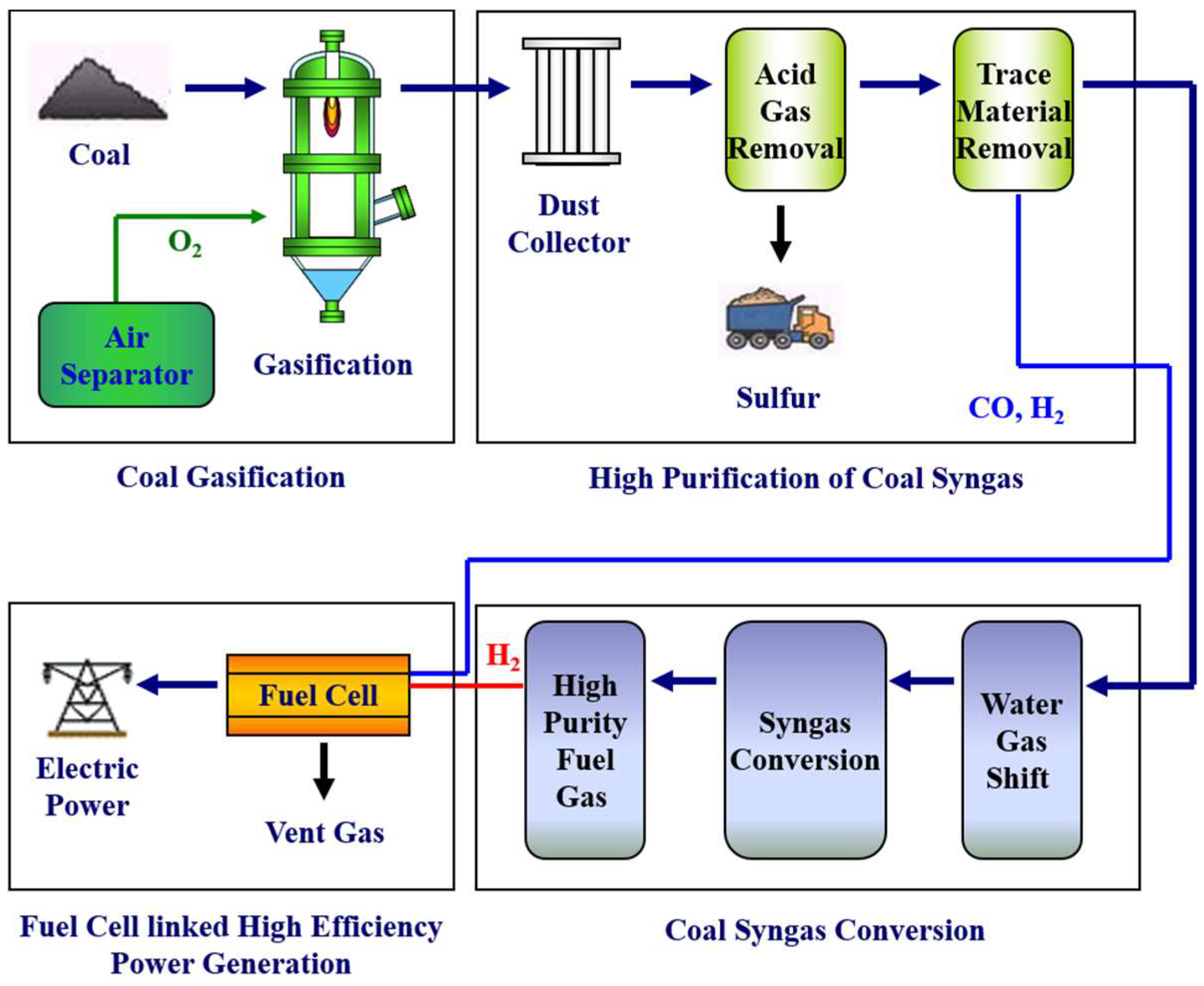
Recent worldwide concerns on global warming and environmental pollution have been at their zenith, and Integrated Gasification Combined Cycle and similar “clean coal technology” for energy supply have attracted renewed technological interests for power generation. Similarly, the Integrated Gasification Fuel Cell technology of
Figure 1 has been introduced as a nearly “zero emission clean coal technology” and related research and development is in full swing [
1]. Syngas produced by coal gasification contains various acidic gases (H
2S, carbonyl sulfide (COS)), particulates, minute quantities of HCl, NH
3, and heavy metal elements. These inherently undesirable constituents should be properly removed for the subsequent operation of fuel cells installed downstream. A series of apparatuses are used to remove acidic gases, and a COS hydrolysis reactor is presently selected for numerical modeling to estimate its performance in terms of operational and geometrical parameters.
Literature on COS hydrolysis research has been concentrated on kinetics of the catalyst or the reaction mechanism thereof. Fiedorow et al. performed extensive studies on kinetics and relevant mechanistic experiments using an alumina catalyst to determine COS hydrolysis performance [
1]. Huang et al. evaluated characteristics of a zinc-promoted alumina catalyst at 150 °C instead of the alumina catalyst of the previous paper [
2,
3]. Hoggan et al. analyzed the COS hydrolysis mechanism of alumina using infrared spectroscopy and a quantum chemistry calculation [
4]. John evaluated activity using various promoters (Na, Fe, Co, Cu, Ni, Zn) of γ-Al
2O
3 catalyst, and Ni and Zn were found to have the best properties [
5]. Bachelier et al. investigated catalytic activity of various oxide catalysts (Z
rO
2, TiO
2, Al
2O
3) [
6]. Shishao et al. also performed COS hydrolysis studies, especially related to its advancement on catalytically active areas of alkali metal oxides at 45–100 °C [
7]. Wang et al. studied how to improve catalytic activity of Al
2O
3 under low humidity conditions as well as how to remove COS by adsorption [
8]. Similar adsorption of COS on activated carbon was also investigated by Wang et al. [
9,
10]. They also efficiently performed COS removal using a metallic catalyst and activated carbon. Wang et al. evaluated adsorption and desorption of low concentrations of carbonyl sulfide by impregnating active carbon [
11]. Yi et al. investigated the effects of catalyst composition on catalytic hydrolysis of COS [
12]. Ping et al. evaluated the effects of Fe/Cu/Ce loading on the coal-based activated carbons for COS hydrolysis [
13]. Sun et al. performed a study on catalytic hydrolysis of carbonyl sulfide and carbon disulfide over an Al
2O
3-K/CAC catalyst at low temperature [
14]. COS hydrolysis using noble metal catalysts was also performed by Zhang et al. [
15] and Yang et al. [
16] who evaluated the catalytic removal efficiency of such noble metal catalysts.
In the previous studies, the kinetics of the COS reaction catalysts or catalytic activation for the improvement of efficiency were mainly studied. However, in order to design an actual plant, evaluation data on the design parameters of the plant are needed. To evaluate the effect of design parameters, a detailed analysis model considering chemical kinetics as well as thermal-fluid flow of the COS reactor is required. Eventually, design direction can be presented through comprehensive evaluation in terms of heat and mass transfer.
In this study, the COS hydrolysis reactor, which is an acidic gas removal system of an Integrated Gasification Fuel Cell system, performed the following procedure to predict the probabilistic performance change with various design parameters (space velocity, length ratio, and temperature per gas hour). First, a numerical model was constructed for the performance analysis of the design parameters in the COS hydrolysis reactor. In this case, numerical modeling was performed considering the dynamics of the chemical change by the catalyst as well as the fluid flow and heat transfer. The reaction model for the catalytic reaction was reflected by using the experimentally derived Kinetics. Using the developed numerical modeling, the effects of various operating and geometric parameters on the performance of the COS hydrolysis reactor were analyzed. Then, the prediction formula was derived through a regression method to predict the performance of the random variation of the design parameters stochastically. Process efficiency and sensitivity were derived using the derived equation and the Monte Carlo simulation method. Finally, guidance criteria on optimized operation of the COS hydrolysis reactor are suggested based on the numerical modeling analysis results.
2. Numerical Model Development
2.1. COS Hydrolysis Reactor Model
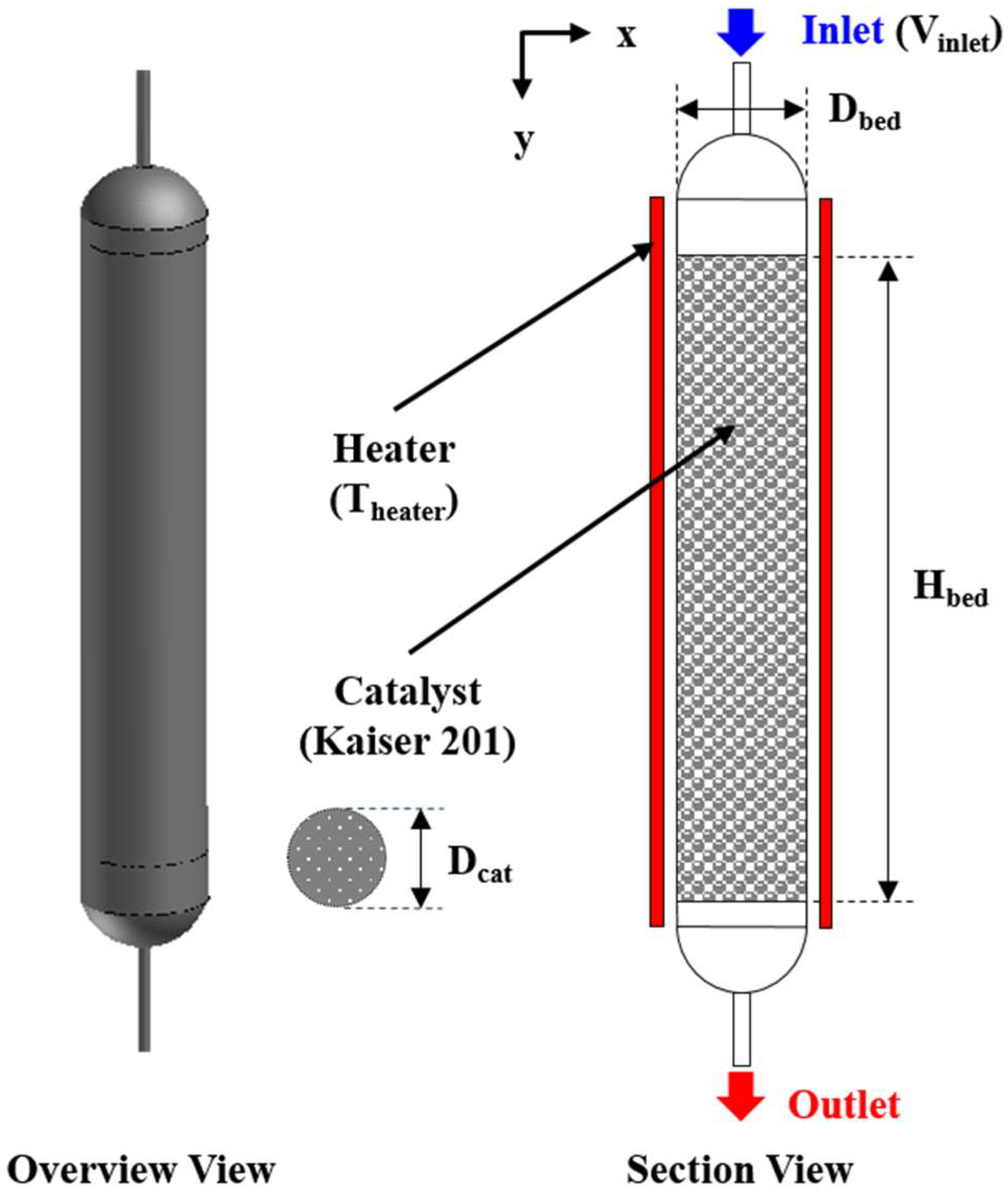
Performance analysis of the COS hydrolysis reactor was evaluated via numerical modeling with variation of operational and geometrical parameters. These modeling results were used to derive relevant parameters affecting reactor performance for proper guidance criteria on efficient reactor design. A schematic diagram of the COS hydrolysis reactor used in the present study is shown in
Figure 2.
A gaseous reactant mixture containing COS is introduced to upper tube. The reactant gas is transported to the lower part of the reactor and enters into the catalyst layer of Kaiser 201. Heat is supplied to the reactor via an external heater to activate the catalytic reaction. A portion of the reactant gas mixture is converted into products after passing through the catalyst layer, and the reacted gas mixture exits via the lower exhaust pipe. The COS hydrolysis reaction is generally affected by gas temperature, is sensitive to operational parameters such as gas hourly space velocity (GHSV), and it also depends on reactor geometry.
For quantitative analysis of transport properties within the COS hydrolysis reactor, internal heat and fluid transfer behavior of gas had to be numerically modeled as did the ensuing chemical reactions. For heat and fluid behavior modeling, commercially available ANSYS Fluent 18.0 software was used; the user-defined function mode enabled numerical modeling of specific chemical reactions. The relevant governing equations for heat and fluid behavior modeling and chemical reaction analysis are described by Equations (1)–(6).
- ➢
Mass conservation equation
- ➢
Momentum conservation equation
- ➢
Transport equation for κ (standard k-ε model)
- ➢
Transport equation for ε (standard k-ε model)
- ➢
Energy conservation equation
- ➢
Species transport equation
An internal fluid flow analysis within the COS reactor was made using mass and momentum conservation equations while turbulent flow was numerically modeled by a standard k-ε model for turbulence analysis. On the other hand, the species transport equation was solved to analyze pertinent chemical reactions, numerically analyzing formation and depletion of reactant gas species and quantitatively giving their concentrations. Reaction kinetics under prevailing parameter conditions were modeled using empirically-derived kinetics and user-defined function enabled calculation and integration on a real-time basis. Lastly, the energy equation was used to incorporate heat transfer as affected by internal heater and heat energy variation as affected by chemical reactions.
2.2. Kinetics and Mathematical Model of Catalyst Bed
Kaiser 201 catalyst was used to activate the COS hydrolysis reaction, and its properties are listed in detail in
Table 1. The catalyst was of spherical morphology and had a constant diameter of 5 mm. Its main constituent was Al
2O
3 and its high catalyzing area enabled improved reaction efficiency.
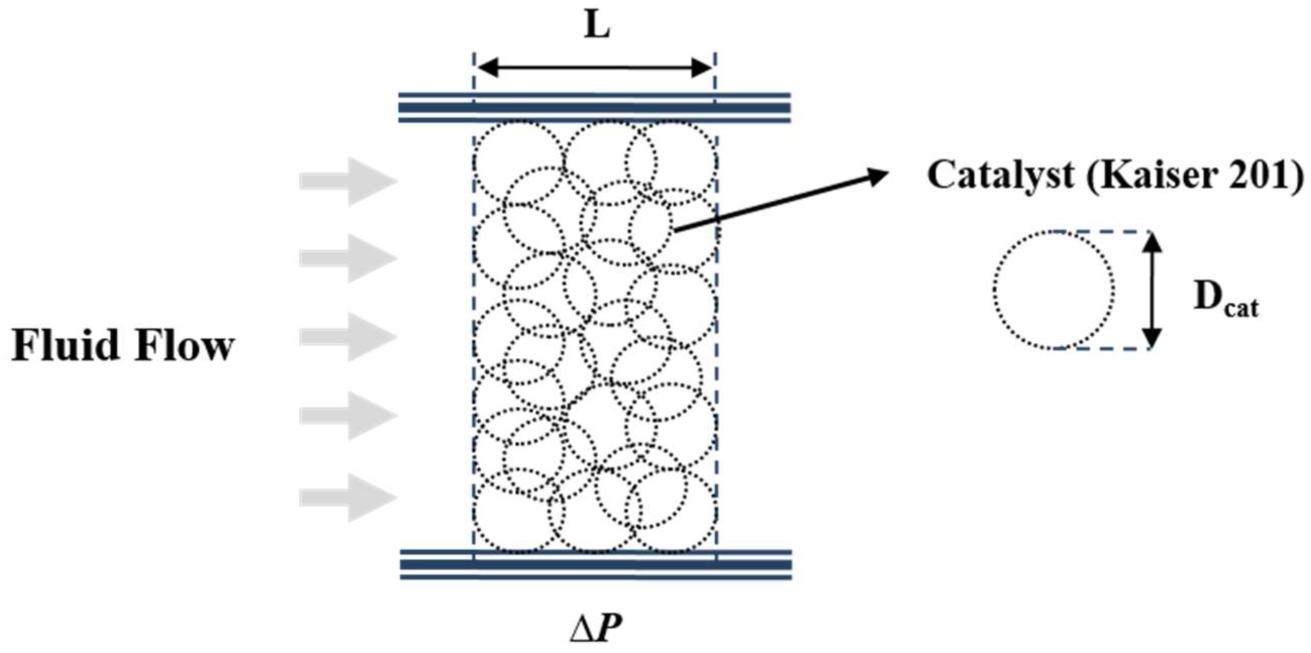
Numerical analysis of the COS hydrolysis reactor necessitated mathematical modeling of the catalyst layer. A porous medium morphology concept was introduced to simulate fluid behavior of the catalyst area. Such porous medium modeling was justified in view of the near-impossible modeling for the individual layer of packed catalysts and for cost-effectiveness, assuming completely spherical and consistent geometry of the catalyst layer to incorporate resistance to fluid flow. This modeling concept is schematically depicted in
Figure 3, and the pertinent Ergun equation is written as Equation (7) to account for the pressure drop caused by fluid resistance.
- ➢
Ergun Equation (Porous Medium)
Viscous and inertia losses are accounted for by the first and second terms of the Ergun equation as applied to a porous medium. Such fluid resistance was used to numerically model reactant gas mixture flow down the catalyst packed layer.
Reaction advancement of the COS hydrolysis reaction is determined by empirically-derived kinetics. Experimentally substantiated kinetics was thus applied in the present study for numerical modeling of reaction kinetics [
17]. The COS hydrolysis reaction and relevant kinetics are represented by Equations (8)–(11), respectively.
- ➢
Kinetics of COS hydrolysis reaction (Kaiser 201)
Here,
Reaction kinetics were simulated by the Eley-Rideal model, where individual modeling parameters were empirically determined. The significant parameters affecting the reaction rate were partial pressure of the gas reactant mixture and temperature, which determined reaction kinetics with utmost sensitivity.
2.3. Properties and Boundary Conditions of the COS Hydrolysis Reactor
Properties of the individual gaseous constituents in the reactant gas mixture are systematically listed in
Table 2 for accurate and comprehensive numerical modeling of the COS hydrolysis reactor, mainly citing NIST(National Institute of Standard and Technology) data.
Inter-diffusion coefficients of major gaseous constituents were calculated using Equation (12) from Perry’s Chemical Engineer’s Handbook [
18].
- ➢
The binary diffusivity equation predicts inter-diffusion coefficients using molecular weight and structure at a specific temperature and pressure, and the calculated inter-diffusion coefficients are accurate within ±5%.
The present numerical modeling necessitates operational parameters to predict performance of the COS hydrolysis reactor. The present modeling was based on ordinary boundary conditions with upper and lower limits suitable for proper evaluation of the COS hydrolysis reactor with variation of operational parameters.
Table 3 summarizes pertinent boundary conditions for the COS hydrolysis reactor. At first, objective hourly capacity of 200 Nm
3/h was converted to velocity, which was varied to estimate its effect on reactor performance. Inlet gas temperature and chemical composition were specified considering the overall Integrated Gasification Fuel Cell (IGFC) process gas temperature and composition; the gas temperature was also carefully cross-checked with variations of the internal heater temperature.
2.4. Numerical Procedures
Numerical modeling of the COS hydrolysis reactor was performed via reactor geometry. A 2-dimensional axi-symmetry model was used for efficient analysis using commercially available ANSYS Fluent 18.0 heat and fluid analysis software. The user-defined function mode of the ANSYS Fluent 18.0 was used to calculate kinetic data, which were used in the relevant governing equations via the source term. The elements for numerical modeling, numbered 54, 173–129, and 814, and the coupled governing equations were obtained by trial and error calculations using the finite volume method and the Semi-Implicit Method for Pressure Linked Equations (SIMPLE) algorithm. For actual analysis, convergence condition was taken to be less than 10−5 of relative uncertainty level.
3. Results and Discussion
The previously suggested geometry and operational parameters of the COS hydrolysis reactor were used to evaluate its performance. In detail, concentration variation of COS and its conversion rate were compared to ascertain individual effects of the modeling parameters. For this, three levels of GHSV, length ratio, and temperature were selected for evaluation of operational and geometrical parameters, as listed in
Table 4. Length ratio is a geometrical factor of the reactor tube and is defined by Equation (13).
All in all, effects of the reactor tube diameter and its length on overall performance were investigated under similar GHSV conditions.
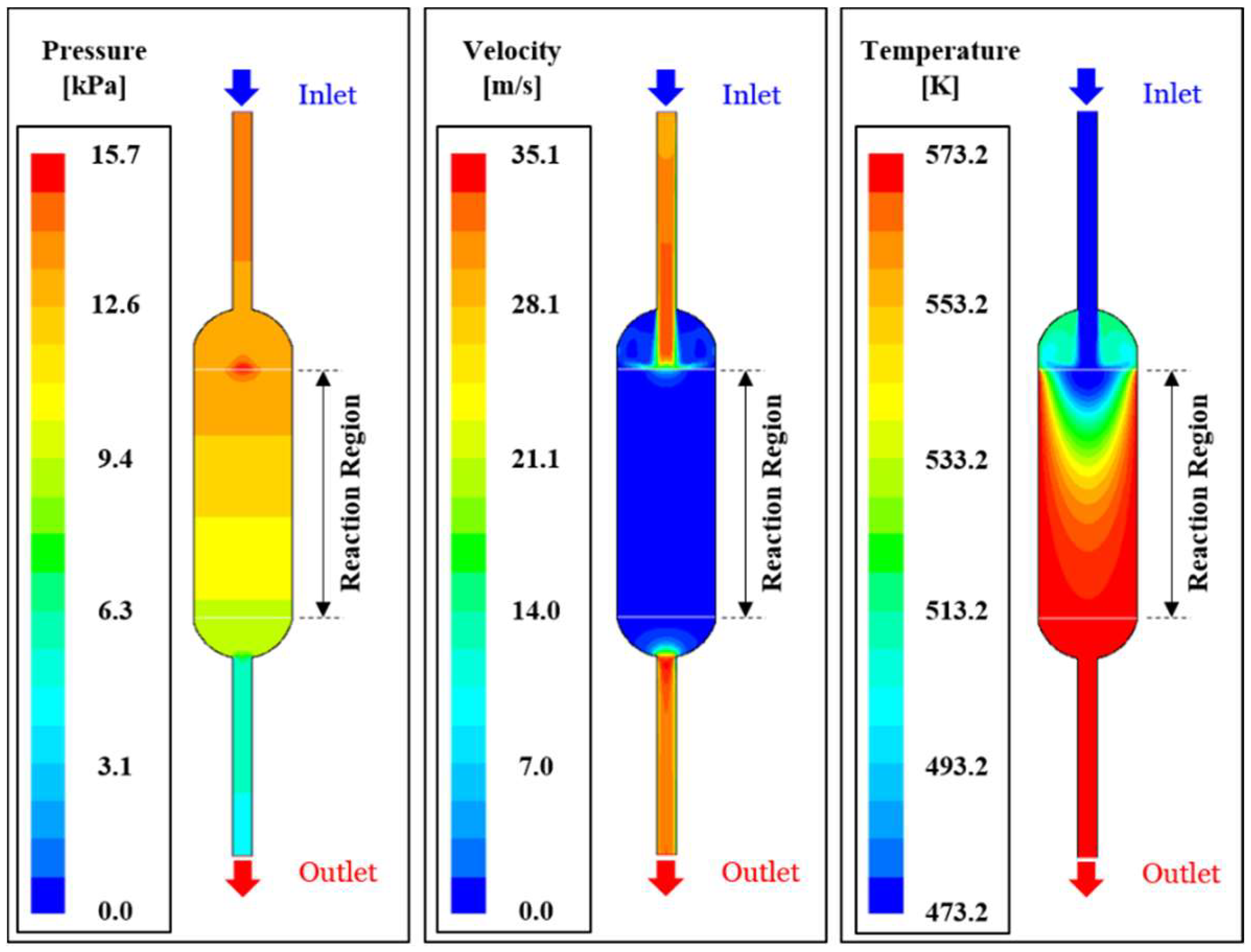
Figure 4 illustrates heat and fluid flow analysis results for reference modeling (GHSV = 1.0, length ratio = 1.0, Temperature = 573 K).
Figure 4a depicts pressure distribution in the reactor, confirming the development of relatively high stagnant pressure at the catalyst area where the reactant gas mixture enters into the high resistance catalytic layer with high porosity.
Figure 4b shows modeling result of the velocity field, showing the jet-type velocity distribution via the reactant gas mixture entering into the (reactor) tube inlet and then rapidly decreasing its velocity by uniform distribution among the catalytic pores.
Figure 4c shows the temperature contour afforded by the external heat supply along the reactor tube wall surface, explaining reactor the gas temperature increase. The catalytic layer with a solid, high thermal conductivity area (porosity 0.4) enabled simultaneous heat convection and transfer, thus confirming high heat transport efficiency.
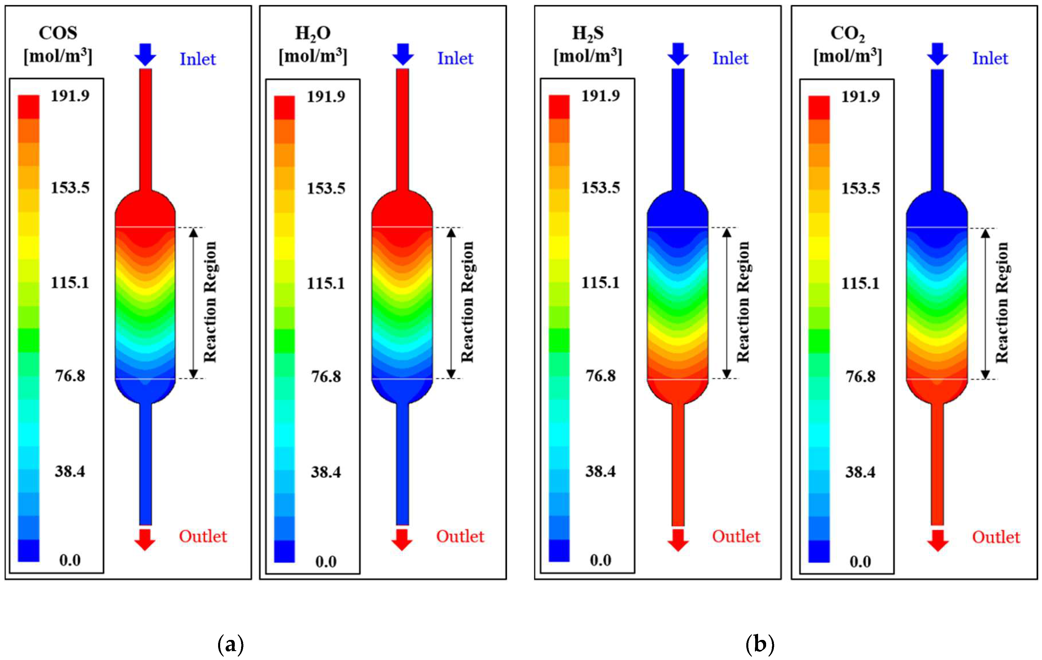
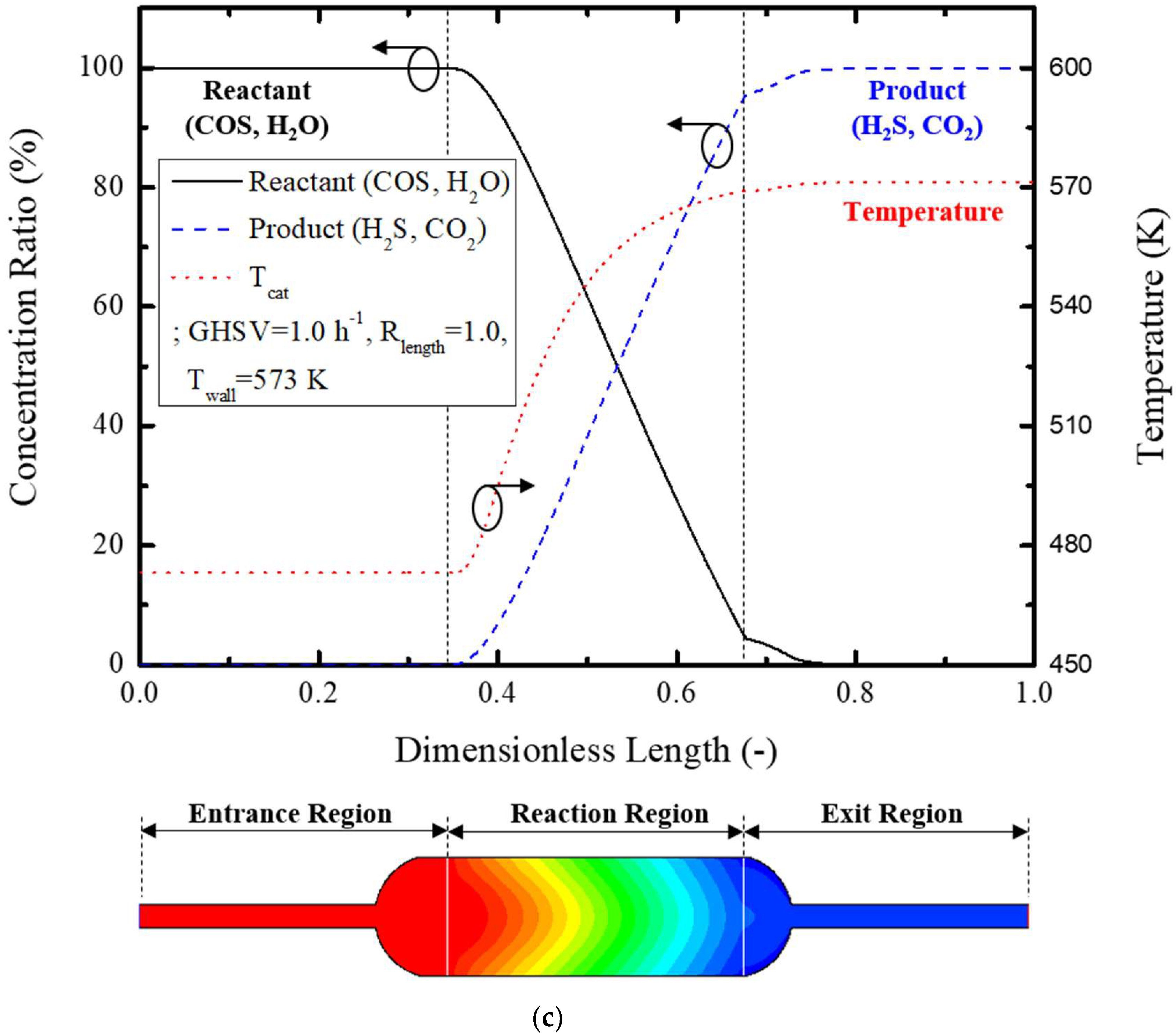
Figure 5 schematically shows the modeling analysis result on reference model (GHSV = 1.0, length ratio = 1.0, Temperature = 573 K). More specifically,
Figure 5a shows the concentration contour of reacting (COS, H
2O) gases, highest concentration at the inlet of the catalytic layer, and gradual reduction in concentration with passage into the porous catalytic layer. The reactant flow is concentrated into the central portion of the catalytic layer by the inlet tube and renders a slow reaction rate caused by low thermal energy from the external heater. Reactant concentration is thus maintained at a high level, and this effect becomes insignificant with passage into the reaction area. On the other hand, H
2S and CO
2 product gas concentration increases with passage into the catalytic reaction area. The reaction rate of the reactants renders a low concentration at the central region and this effect is gradually cancelled with passage into the outlet.
Figure 5c graphically illustrates reactant concentration, products concentration, and temperature variation at the center of the reactor. The reactants’ concentration rapidly decreases as they pass the reaction zone, while proportionately increasing the products’ concentration.
Equation (14) was used to evaluate reactor performance based on the concentration contour of COS gas at the inlet and outlet of the reactor. The catalytic conversion rate of COS is defined as the ratio of the concentrations of reacted COS to the originally supplied COS at the inlet of the reactor, and the COS conversion rate of the reference model is 41.1%.
Temperature variation inside of the reactor showed a delayed response caused by the transport of the heat energy supplied by the external heater, which changed the reaction rate and affected the reactor performance.
Conversion rate of the reactant gas mixture was estimated and compared using the suggested numerical modeling to analyze the effects of individual parameters.
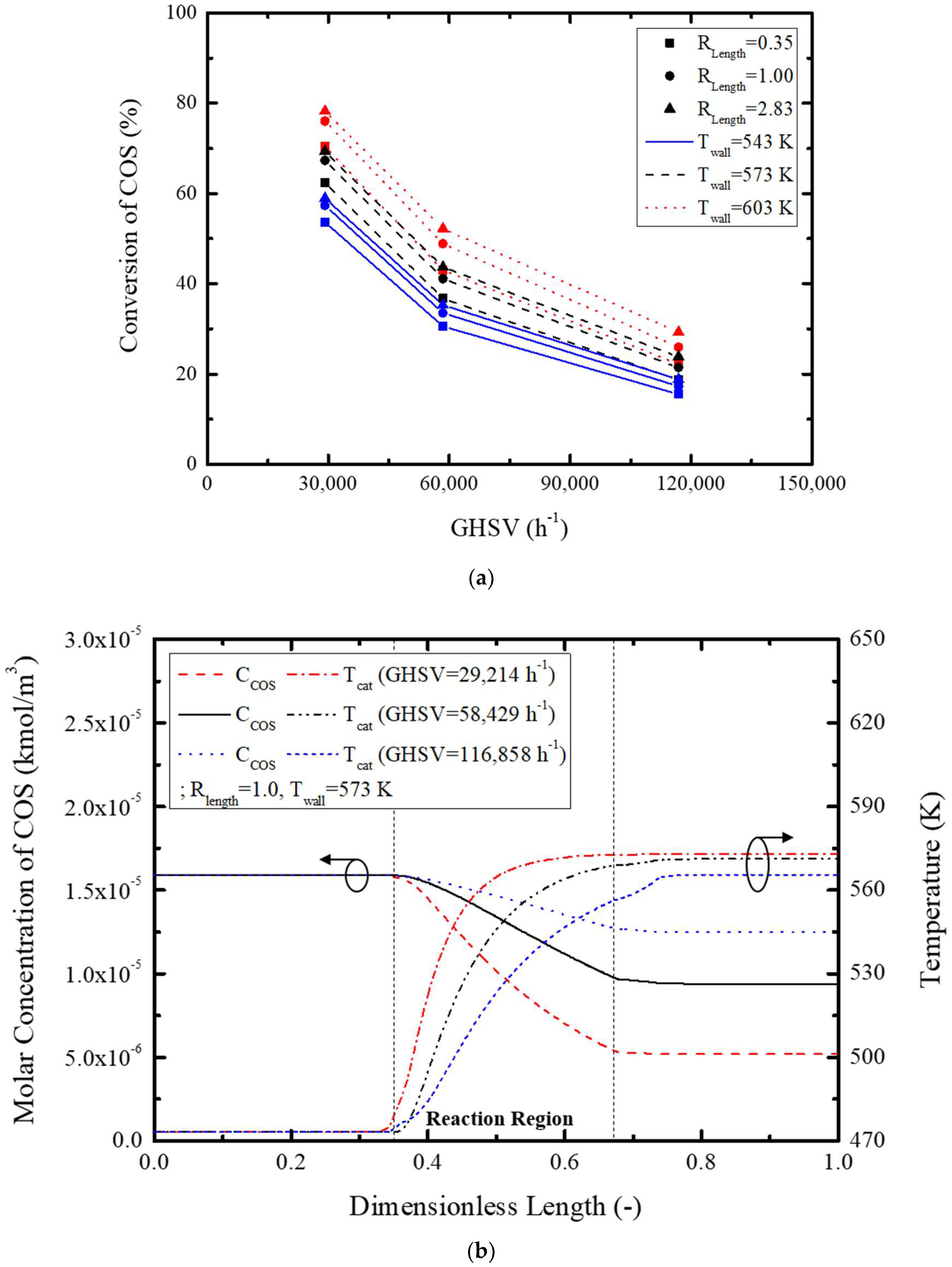
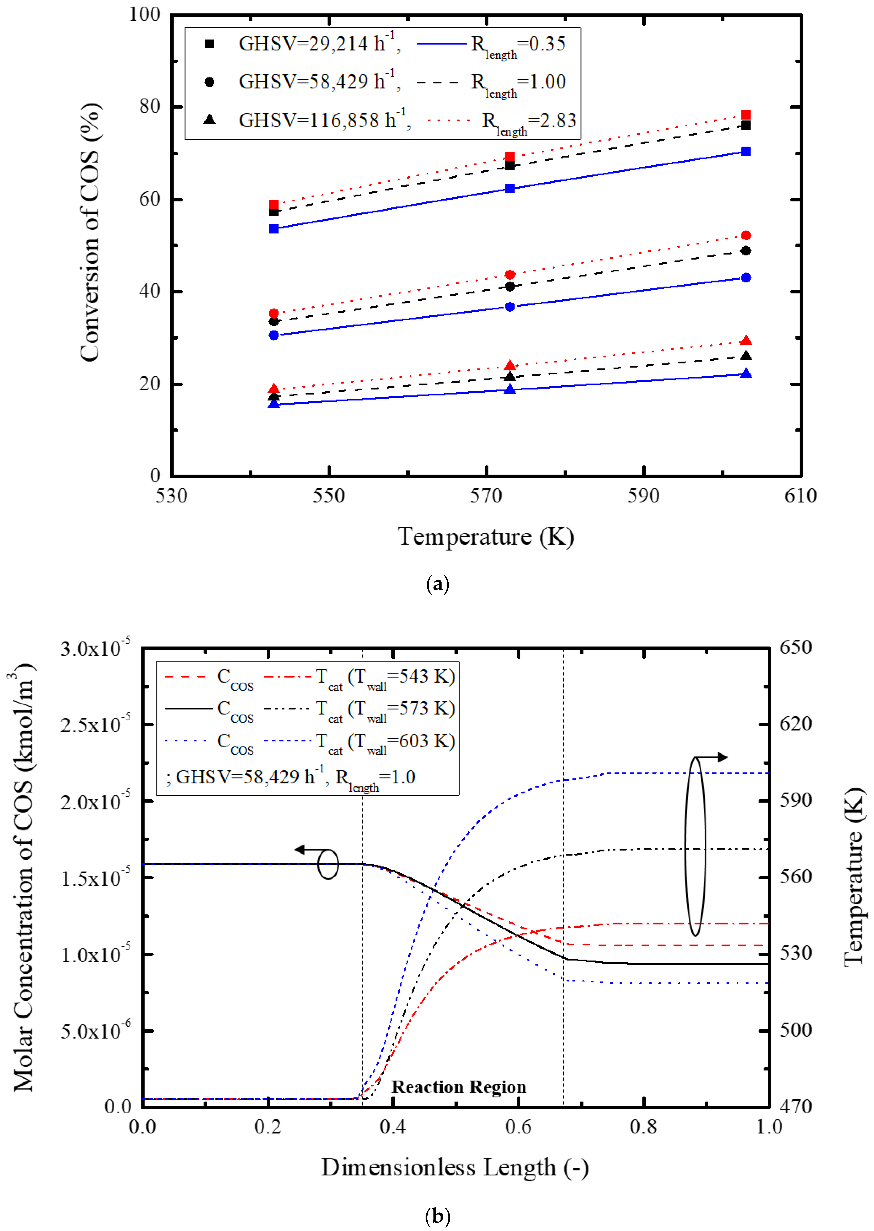
Figure 6 shows conversion rate, concentration, and temperature variation with GHSV.
Figure 6a graphically depicts conversion rate variation with GHSV, showing a maximum 50.1% conversion rate with an increase in GHSV. This is attributed to increased GHSV for an equivalent amount of catalyst, thus decreasing the conversion rate. The concentration and temperature variation of
Figure 6b clearly illustrates a slow catalytic reaction with GHSV via a reduction in temperature by the increased reactant gas mixture flow, and increased reactant mass renders a slower decrease in reactant gas concentration. All in all, low GHSV increases the reactor temperature and activates the reaction further, resulting in a higher reaction rate. Besides, COS concentration rapidly decreased by the relatively small quantity of reactants. GHSV selection is thus very important for optimized reactor design.
Secondly, the effect of the length ratio on the reactor performance was investigated by the variation of diameter and its length.
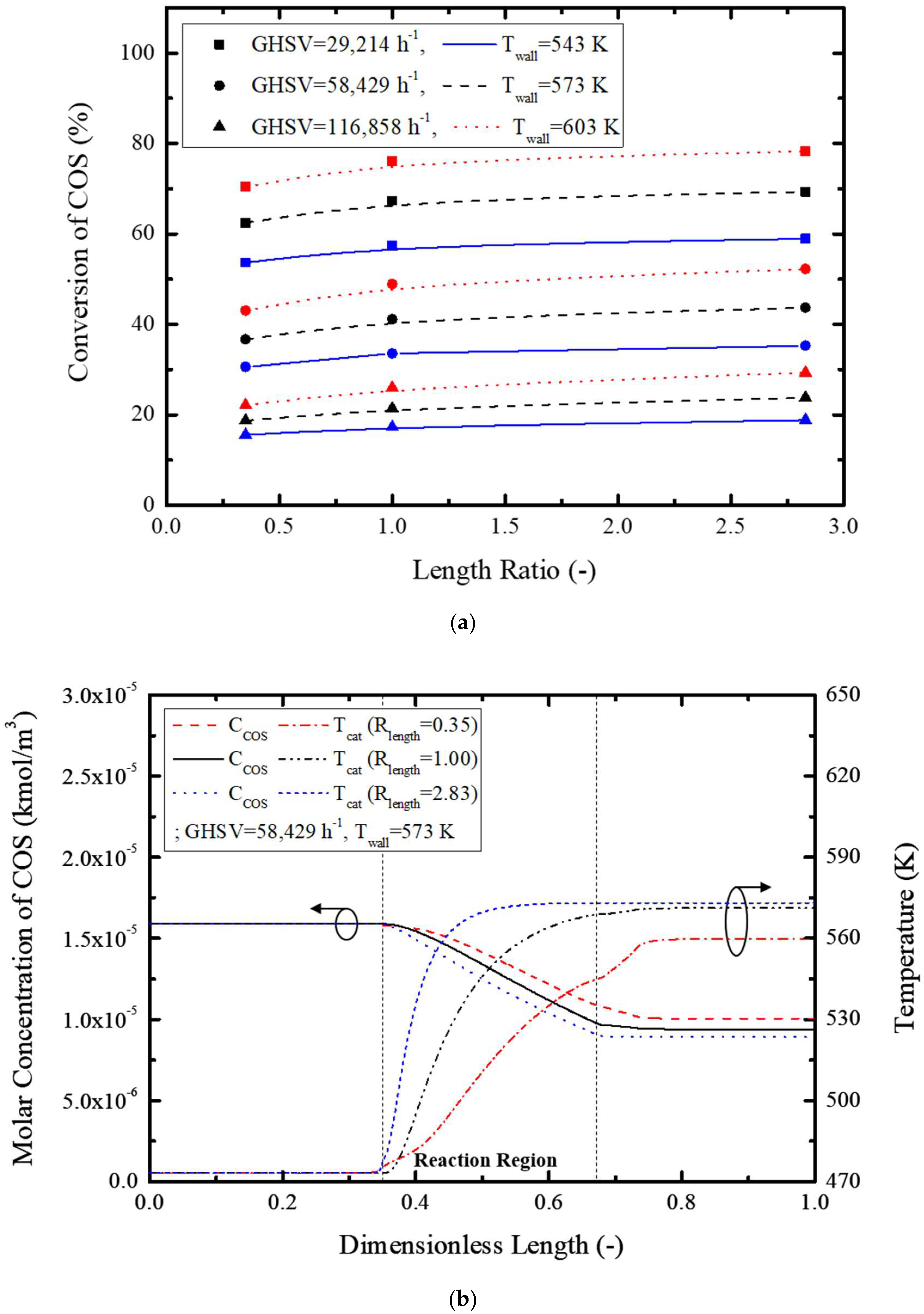
Figure 7 shows the effect of the length ratio on the conversion rate, concentration, and temperature variation.
Figure 7a graphically shows the conversion rate, and a maximum 9.2% increase was possible with an increase in the length ratio for the same GHSV and reactor tube wall temperature.
Figure 7b shows the effect of the length ratio on the COS concentration inside of the reactor and temperature; the COS concentration rapidly decreased with the length ratio, while temperature increased proportionally. This is attributed to facile heat transfer and radial gas diffusion in the tube via reduction in the reactor diameter and an increased tube length, respectively, causing an increased reaction rate. Therefore, an optimized length ratio could result in a higher COS conversion rate.
Lastly, the effect of external heater temperature on the reactor wall was investigated by comparing the external tube wall temperatures.
Figure 8 shows effects of the reactor wall temperature on conversion rate, reactant concentration, and inside temperature of the reactor.
Figure 8a shows variation of the conversion rate with temperature on the reactor wall (547–603 K), showing a maximum 19.3% increase in the COS conversion rate for the same GHSV and length ratio.
Figure 8b also shows the effects of variation of the reactant gas concentration and inside reactor temperature on the reaction rate and conversion rate, mainly confirming the beneficial effects of reactor wall temperature. This cogently shows that a higher heater temperature is required for a high COS conversion rate. However, higher heater temperature ensures more energy consumption, and an enhanced GHSV is more important than a heater temperature increase, thus requiring optimization of other operational variables such as GHSV and length ratio before finalizing the reactor wall temperature for more efficient operation of the COS hydrolysis reactor.
In view of the previously performed numerical modeling analysis results, regression analysis was made incorporating GHSV, length ratio, temperature, and conversion rate: Equations (15)–(18).
Here,
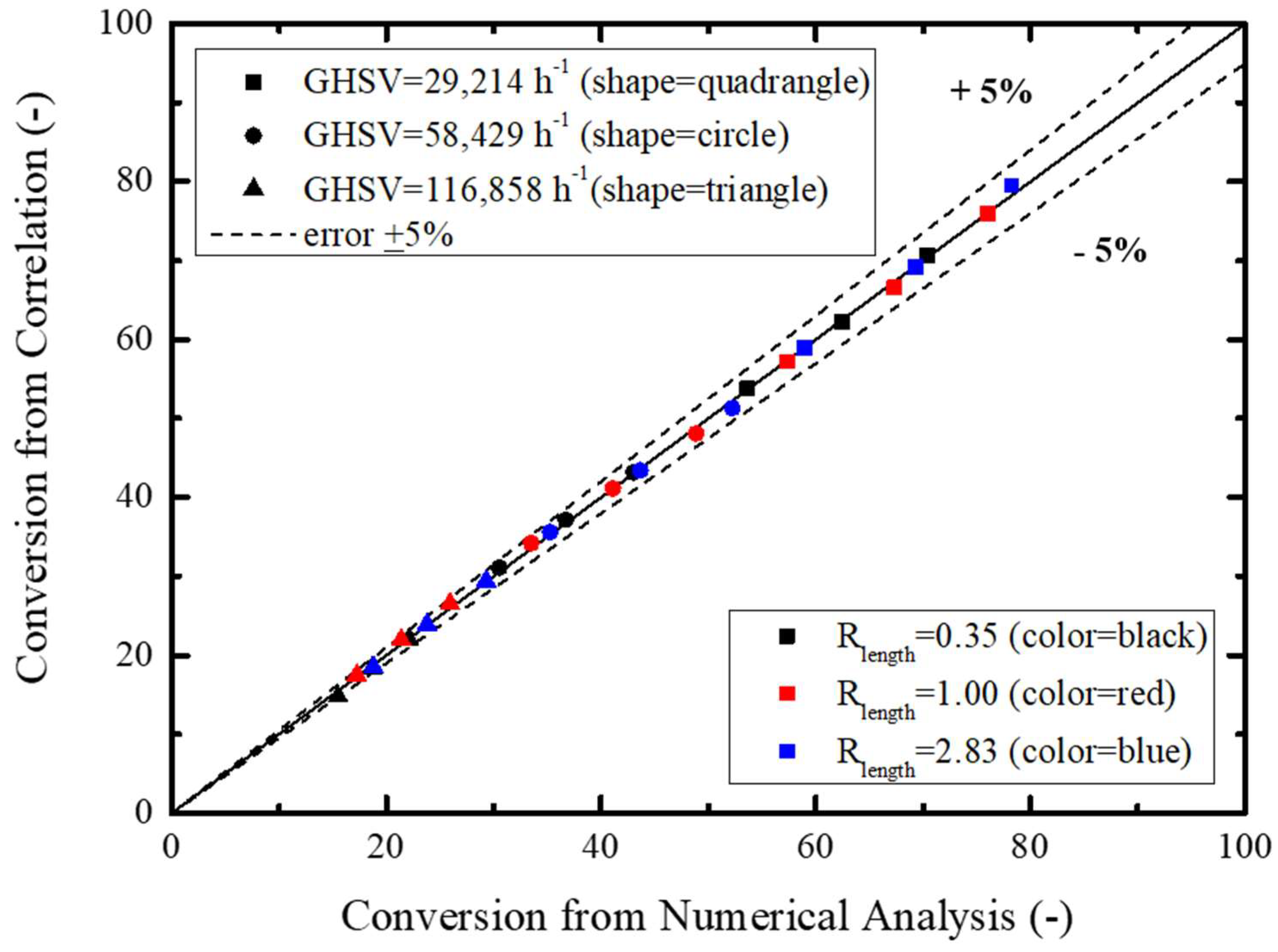
Figure 9 schematically compares Equation (15) and the numerically modeled COS conversion rate, showing an accuracy of ±10%. Based on this result, the Monte Carlo simulation was performed for sensitivity confirmation of individual parameters considering probability distribution characteristics of GHSV, length ratio, and temperature for estimation of the COS conversion rate.
Monte Carlo simulation is usually performed by adopting a stochastic model for probabilistic distribution of a specific parameter with uncertainty involved. In general, an analytical solution is obtained for a definitely defined model, but a stochastic model usually does not guarantee such a solution. Numerical modeling is thus needed for an analytic solution, and the probability distribution of a specific parameter should be obtained by a trial and error method.
For that purpose, performance parameters of a COS hydrolysis reactor were chosen to be GHSV, length ratio, and temperature to estimate performance efficiency via probability analysis within the variation range of individual parameters. For this, variation ranges of GHSV, length ratio, and temperature were selected to be 10,000–15,000 h
−1, 0.884–7.062, and 543–603 K, respectively. Variation ranges were taken as a 3σ level considering reasonably efficient reactor performance and normal distribution with relevant average and standard deviation values, as listed in
Table 5.
Table 6 lists the distribution of individual performance parameters obtained by using normalization of individual performance parameters as specified in
Table 5.
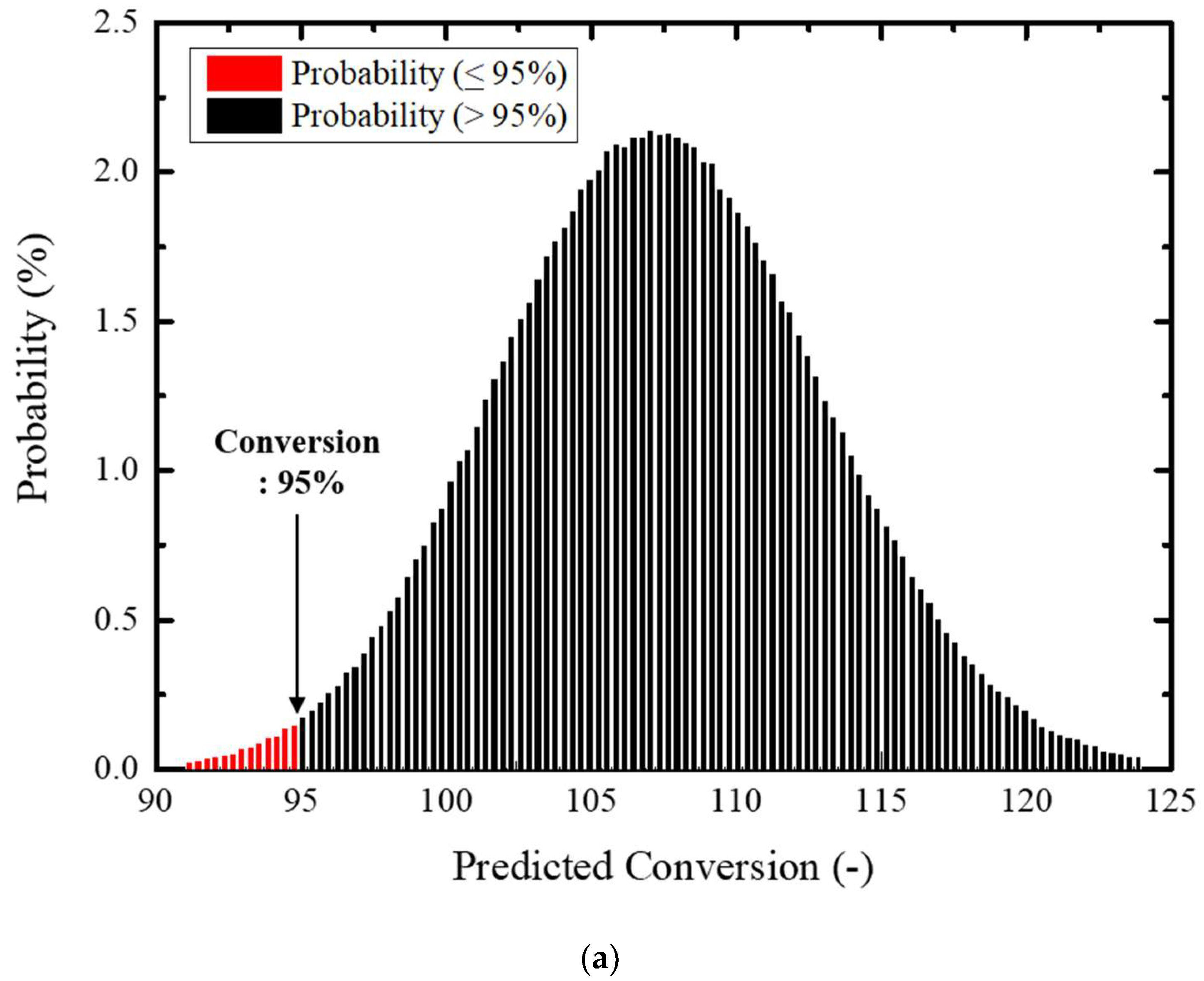
In the application of the Monte Carlo simulation, more than 1,000,000 random numbers were created for increased probabilistic credibility. Variation of individual performance parameters was defined within a 3σ level considering a credible level of operational control.
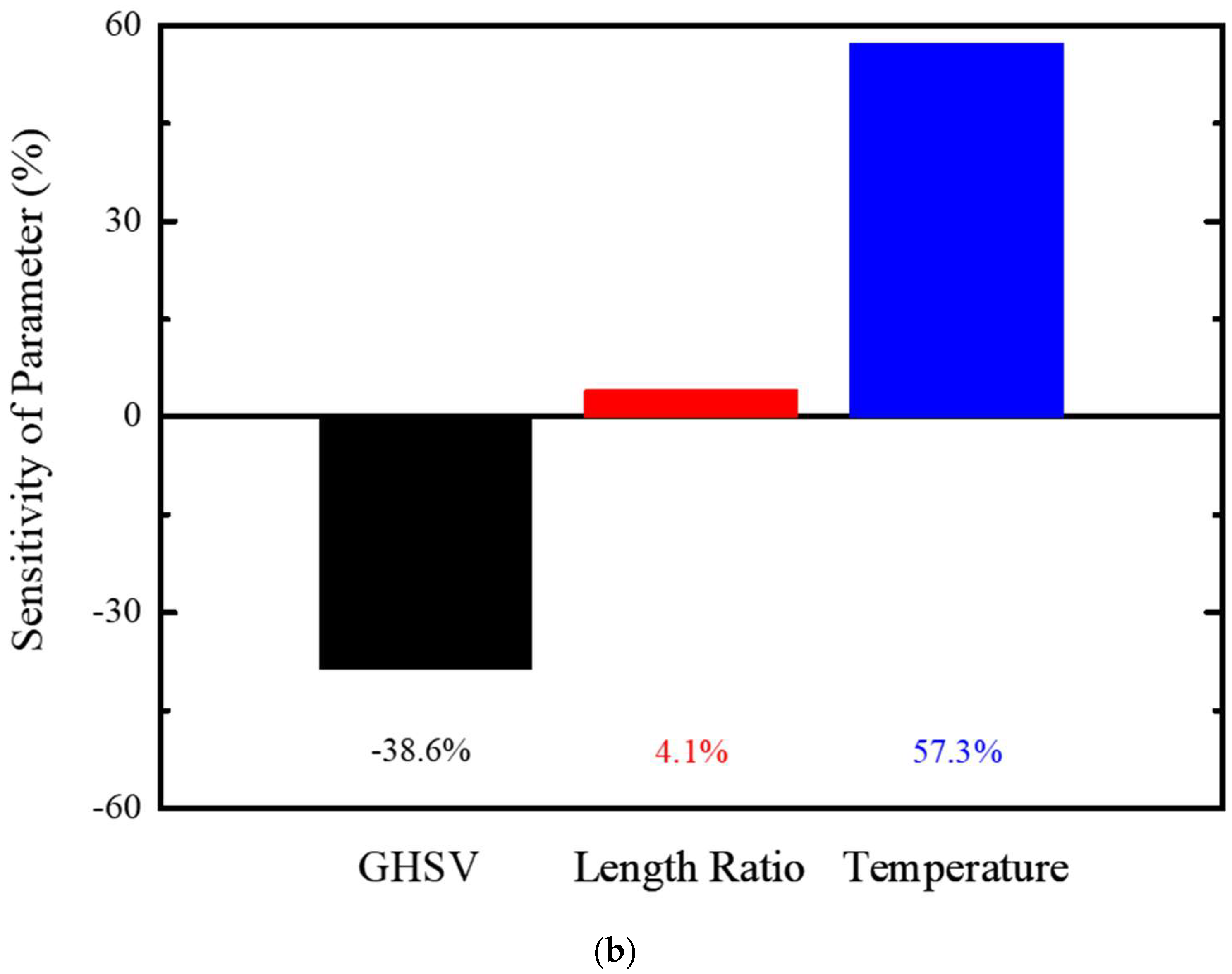
Figure 8 illustrates the COS conversion rate for sensitivity of performance parameters and their distribution.
Figure 10a was obtained by limiting the variation range of the GHSV and temperature within a 3σ level and more than a 95% of conversion rate efficiency with reliability level of 98.9%. On the other hand, sensitivity of the COS performance efficiency was evaluated in
Figure 10b, and temperature, GHSV, and length ratio were rated as important at 57.3% (temperature) and −38.6% (GHSV). Therefore, GHSV and temperature should be controlled within a tolerable margin for efficient performance improvement of the COS reactor.
