Article

A MQTT/MQTT-SN-Based User Energy Management System for Automated Residential Demand Response: Formal Verification and Cyber-Physical Performance Evaluation

Key Laboratory of Control of Power Transmission and Conversion, Shanghai Jiao Tong University, Dongchuan Road 555, Minhang District, Shanghai 200240, China
*
Author to whom correspondence should be addressed.
Appl. Sci. 2018, 8(7), 1035; https://doi.org/10.3390/app8071035
Submission received: 29 April 2018 / Revised: 1 June 2018 / Accepted: 13 June 2018 / Published: 25 June 2018
(This article belongs to the Special Issue Smart Grid and Information Technology)

Abstract

:
As one of the typical cyber physical systems (CPS), the user energy management system (UEMS) plays an increasingly significant role in the smart grid, such as participating in automated demand response (ADR). Traditional analyses related to the UEMS in ADR programming mainly focus on energy management strategies or algorithms, where the interdependence and interplay between the cyber system and the physical system is neglected. This paper firstly presents an ADR control strategy of the UEMS with the objective of minimizing electricity bills and meeting users’ comfort constraints. Then, a hybrid scheme including Message Queuing Telemetry Transport (MQTT) and Message Queuing Telemetry Transport for Sensor Network (MQTT-SN), which are publish-subscribe communication protocols, is developed to establish the cyber system of the UEMS. To evaluate the cyber-physical performance of the UEMS in ADR programs, the hybrid dynamic models of major behaviors of the UEMS are proposed and a UPPAAL (http://www.uppaal.org/)-based methodology of the formal specification and verification is also proposed. In case studies, the impact of communication reliability on the proposed ADR control strategy is studied and the quality of service (QoS) mechanism provided by MQTT/MQTT-SN is demonstrated as a cost-effective solution for the ADR control strategy under unreliable communication.

1. Introduction

The cyber physical system (CPS) refers to the next generation of engineering systems. It requires tight integration of computation, communication, and control technologies to achieve stability, reliability, and expandability, and has been applied in many application domains such as transportation, health care and energy [1].
With the deep and pervasive application of information and communication technologies, smart grid has become one of the vital CPSs [2]. To improve the safety and efficiency of smart grid, the user energy management system (UEMS) plays an increasingly crucial role in serving as an agent of consumers to respond to demand response signals, i.e., automated demand response (ADR) [3].
Many previous works related to the UEMS in ADR programs focus on energy management strategies or algorithms. Zhang et al. developed a demand response strategy with the application of machine learning and optimization scheduling [4]. Wen et al. formulated a fully automated EMS rescheduling problem as a reinforcement learning problem [5]. Hansen et al. applied partially observable Markov decision process approaches in home energy management system (HEMS) for minimizing the household electricity bills in the real-time pricing market [6]. Erol-Kantarci et al. compares an in-home energy management application with an optimization-based residential energy management scheme in the aspect of energy saving and peak load shift under the presence of local energy generation capability, prioritized appliances, and for real-time pricing [7].
Cyber systems such as communication networks and computing modules are indispensable for those strategies or algorithms. However, the cyber systems are always assumed to be ideal in these literatures. In other words, these algorithms may lose efficacy in real projects due to the interdependence and interplay between the cyber system and physical system [8]. For instance, unreliable communication cannot conduct commands exactly, so it may deteriorate the performance of algorithm. To reduce the risks and to develop methods for improving system efficiency, the cyber-physical characteristics of the UEMS should be studied.
Besides the communication reliability, as a networked control system composed by intelligent electronic devices, a UEMS must accomplish some logical verification to achieve reliable control. Although the formal methodology is one of the critical methods in CPS analyses and can ensure the system robustness from the aspect of logic, there are rare researches related to the formal methodology analyzing the reliability of the UEMS in ADR. The formal-methodology-based cyber-physical analyses mainly focus on distribution networks, such as intelligent substations based on IEC61850 [9,10,11] or microgrids [12,13].
The manuscript could be divided into three parts: the optimization problem of the UEMS, the basic behaviors of intelligent terminal in UEMS, and the cyber-physical interplay analyses. The optimization problem is to achieve the optimal operation of the physical system and it provides a problem scenario, i.e., optimal operation strategies for multiple electrical heaters in this paper. The basic behaviors aim to establish formal specifications and verifications of the cyber system and to present a way of cyber-physical interplay. The two parts mentioned above are both preparation work for the last cyber-physical interplay analyses.
The contributions and innovations of this paper are as follows:
(1)
The interdependence and interplay between the cyber system and the physical system of the UEMS is analyzed and the impact of communication reliability on the ADR performance is studied.
(2)
The major behaviors of intelligent devices in the UEMS are summarized and the corresponding basic MQTT/MQTT-SN topics for the UEMS are proposed. Some modifications are made on original MQTT/MQTT-SN for convenience and high efficiency. For example, the subscription or registration of those topics is added into the connection procedures.
(3)
The hybrid dynamic models of major behaviors of intelligent devices in the UEMS are proposed and the corresponding formal verifications are implemented via UPPAAL-based methodology.
(4)
The quality of service (QoS) mechanism provided by MQTT/MQTT-SN is demonstrated as a cost-effective solution for the ADR control strategy under unreliable communication.
In the following sections: in Section 2, the scenario, architecture, and optimization strategy of the UEMS for ADR is presented. In Section 3, MQTT/MQTTSN is introduced to establish the cyber system of the UEMS and the major behaviors of intelligent devices in the UEMS are abstracted. Section 4 presents the corresponding hybrid dynamic models and implements formal verifications based on UPPAAL. Section 5 evaluates the cyber-physical performance of the ADR control strategy of the UEMS. Finally, the paper concludes with a summary of the main points in Section 6.

2. The Scenario, Architecture and Optimization Strategy of the UEMS for ADR

2.1. The Scenario of the UEMS

Due to serious air pollution in the north of China, the government is vigorously promoting the electric-heating-reform-project and many electric heaters are put into service. The widely used electric heaters only have two running states, on and off, and cannot adjust their power continuously. Due to the absence of temperature sensors, these electric heaters cannot change their working state according to the indoor temperature automatically. Obviously, the manually controlled electric heaters cannot precisely guarantee the comfort of users, let alone optimally response to the real-time electricity price. To minimize the electricity bill while guarantee user comfort, a UEMS that executes an optimal strategy according to the indoor temperature and electricity price is indispensable.

2.2. The Architecture of the UEMS

The architecture of the UEMS is depicted in Figure 1.
The gateway, which is one of the critical components of the UEMS, is regarded as a middleware between the cloud layer and the sensor layer. It reports the data acquired from sensors to cloud while delivering commands generated by cloud layer to actuators. Besides gateway, smart sockets and temperature sensors are also essential for the UEMS. Smart sockets, which are physically connected to electric heaters, support appliance-based metering and direct load control. Temperature sensors are responsible for acquiring indoor temperature, which is beyond the capability of the smart sockets but necessary for the ADR control strategy of the UEMS. The smart sockets and the temperature sensors are collectively referred to intelligent terminals in this paper.
Additionally, intelligent terminals communicate with the local gateways according to MQTT-SN protocols, which relies on non-IP wireless networks. Incidentally, ZigBee technology is adopted in this paper to support the local non-IP wireless networks. The communication between the cloud layer and the gateway layer is based on MQTT protocols, which relies on IP-based protocols such as TCP/IP. The MQTT/MQTT-SN would be introduced in detail in Section 3.

2.3. The Optimal Operation Strategy of the UEMS for ADR

In this paper, multiple rooms separately equipped with electric heaters are taken as a paradigm. The user comfort is defined as a temperature band. The optimal ADR strategy is described as a cooperative scheduling of the electric heaters in the multiple rooms that can obtain the minimal electricity bill while the user comfort is not violated. A concise but representative optimization problem can be formalized as Equation (1):
min n = 1 N m = 1 M ( p r i c e ( m ) u n m p n Δ t ) s . t .   T l T ( n , m ) T h   n N , m M * T ( n , m ) = T o m ( T o m T ( n , m 1 ) ) ε n + Q n R n ( 1 ε ) u n m 1 ε n = e Δ t / R n C n
where N is the total number of rooms, M is the total number of time slots and M = T o p t / t , T o p t is the duration of the optimization problem (min) and t is the time step (min), p r i c e ( m ) is the electric price of the mth time slot, u n m denotes the operating state of the electric heater in the n th room at the mth time slot, p n denotes the power of the electric heater in the n th room, T l and T h are the lowest and the highest temperature of users’ comfort respectively. The equivalent thermal parameter (ETP) model [14] is adopted to quantitatively describe the dynamic change process of the indoor temperature. T ( n , m ) denotes the indoor temperature (°C) in the n th room at the mth time slot, M * is the set of the time slots with comfort demand, T o m is the ambient temperature (°C) at the mth time slot, Q n is the heating rate of the electric heater at the n th room, which is determined by the product of power and the energy efficiency ratio, i.e., μ n p n , R n is the equivalent thermal resistance (°C/W) of the n th room and C n is the equivalent heat capacity (J/°C) of the n th room.For brevity but effectiveness, those rooms are deemed to be approximately thermally decoupled and thermal interaction between those rooms is omitted.
According to the above optimization programming, a day-ahead electric heater control 0–1 matrix U M × N can be eventually obtained where 1 denotes the electric heater is turned on and 0 denotes the electric heater is turned off.

3. The MQTT/MQTT-SN Based Cyber System of the UEMS

Message queuing telemetry transport (MQTT) and Message queuing telemetry transport for sensor network (MQTTSN) are instant messaging protocols proposed by IBM [15]. This paper utilizes MQTT-SN and MQTT cooperatively to establish the cyber system of the UEMS. The former serves as the data exchange protocol in low-bandwidth and instable wireless sensor network (such as ZigBee) while the later focuses on IP-based networks (such as TCP/IP).

3.1. The Advantages of the Co-Use of MQTT/MQTT-SN

As one of the typical CPSs, the UEMS requires that the communication mechanism should be real-time, reliable, compatible, and scalable. Thus, the co-use of MQTT/MQTT-SN, which could satisfy the above requirements, is proposed. The advantages of MQTT/MQTT-SN are as follows:
(1)
MQTT/MQTT-SN supports publish-subscribe mechanism. Various studies have proven that publish-subscribe-based communication outperforms the client/server (C/S)-based communication [16,17,18]. MQTT/MQTT-SN provides topic-centric publish/subscribe mechanism to realize one-to-many data transmission, which improves the expansibility of the protocol as well as the instantaneity of the data transmission. Hence, a MQTT/MQTT-SN-based UEMS gives full expression of data-driven concept. The subsystems and modules are fully decoupled and only keep loose connections via the topic.
(2)
The co-use of MQTT/MQTT-SN could support not only IP-based networks but also non-IP networks. Due to the outperformance of publish-subscribe mechanism marked by MQTT/MQTT-SN, MQTT has attracted increasing attention in smart grid [19,20]. However, the above research only focuses on the relatively resourceful and IP-based scenarios while resource limited, and non-IP IoT devices are hardly applicable.
(3)
The transformation between MQTT and MQTT-SN is tractable. Since it is formidable to design a communication standard which is compatible with various IoT devices and suitable for every running scenario (IP-based networks and non-IP networks), a practical approach is to design a communication protocol that is transplantable and independent of any specific wireless technique, while the gateway is responsible for protocol transition to support interconnection among IoT devices. Considering the similarity and simple effective conversion between the MQTT and the MQTT-SN, the co-use of the MQTT and the MQTT-SN is a cost-effective solution.
In conclusion, we believe that MQTT/MQTT-SN is a more appropriate solution for cyber systems of the UEMS.

3.2. The Quality of the Service of MQTT/MQTT-SN

As mentioned above, the communication of the UEMS should be real-time and reliable. However, the ZigBee-based local wireless network has characteristics of low power dissipation, low-cost, low communication rate, and limited features, where stable communication cannot be always guaranteed. Hence, MQTT/MQTT-SN provides the QoS mechanism to support the real-time requirement of messages so that the probability of successful reception can be improved.
Table 1 describes various QoS levels in MQTT-SN.

3.3. The Major Behaviors of Intelligent Terminal in the UEMS

In our opinion, no matter how changeable the type and requirement of the intelligent device in the UEMS is, the major behaviors of the device are nothing but connection, measurement, control, and upgrade. Maybe the reasons can be listed as follows:
(1)
Connection. On one hand, UEMS is required to be compatible with various known and unknown devices. In addition, when a new sensor or actuator is going to be installed in the UEMS, or the functions of some devices are going to be updated or modified, the system will not be disrupted, that is, the system shows good expansibility. Thus, to join in the UEMS, the first basic behavior of intelligent terminals is the connection.
(2)
Measure and control. On the other hand, no matter how changeable the type and requirement of the terminal is, the functions of terminals are nothing more than measure and control. The former is realized by sensors, such as environmental monitoring sensors, smoke detection sensors and so on, and can be regarded as the input of the UEMS; the latter is supported by actuators, such as infrared controllers, switches and so on, and can be regarded as the output of the UEMS.
(3)
Upgrade. In addition, to make full use of installed devices, the long-life terminal should be updated regularly to meet modified demands, that is, remote firmware upgrade should also be a necessary function of terminals.
Figure 2 illustrates a general model of the four universal behaviors for an intelligent terminal in the UEMS.

4. A UPPAAL-Based Formal Methodology for the UEMS

The formal methodology, which focuses on the safety and stability of a system from the aspect of logical analyses, mainly refers to the formal specification and the formal verification. It abstracts functions and processes of a system into logical expressions and verifies whether system behaviors conflicts predefined rules.
Although simulation allows one to experiment the behavior of a system in a specific operational condition and quickly detect some errors, the result obtained from the simulation may be biased beyond test scenarios.
Compared with the simulation, due to the analyses of all possibilities of evolution of a system’s behavior, the formal specification and verification allows one to obtain more conclusive results at the expense of time-consuming analyses. As a result, it is advantageous to use simulation complementarily to formal verification, that is, simulation is responsible for finding more simply detectable bugs and then the formal verification tries to look for undetected errors by simulation.

4.1. Analyses Techniques of the Formal Methodology

Since the UEMS is a real-time system, the analyses of the UEMS need to take time evolution into account. Consequently, timed automaton is adopted in this paper to construct abstract models of UEMS behaviors.
A timed automaton is essentially a finite automaton extended by time restrictions. As a formal analyses technique, the timed automaton has rigorous definition. In general, a timed automaton is defined as a tuple ( S , S 0 , C l k , A c t , V a r , E ) , where
(a)
S is a finite set of states,
(b)
S 0 S is the initial state,
(c)
C l k is a finite set of clocks,
(d)
A c t is a finite set of actions,
(e)
V a r is a finite set of variables,
(f)
E is a finite set of transitions. A transition is a tuple ( s , a c t , g , c l k , v a r , s ) indicating that, starting by the state s , the automaton executes the action a c t , if the constraint g is satisfied; clocks of c l k are reset, variables of v a r are updated and the new state is s .
The constraint g is defined as Equation (2). Incidentally, Equation (2) applies Backus-Naur Form (BNF).
g : : = g _ c l o c k | g _ d a t a | g , g g _ c l o c k : : = c l k < t | c l k < = t | c l k = = t | c l k > = t | c l k > t g _ d a t a : : = e x < c o n s t | e x < = c o n s t | e x = = c o n s t | e x > = c o n s t | e x > c o n s t e x : : = c o n s t | e x | e x + e x | e x e x | e x × e x | e x / e x
where ‘:=’ means ‘defined as’ and ‘|’ means ‘or’. Equation (2) implies that the constraint g is a logic expression of time (g_clock) or a logic expression of data (g_data) or a combination of the above two. The logical expression indicates a variable (clk or ex) is less than, no more than, equivalent to, no less than or more than a preset value. A variable of data (ex) can be further defined as a constant or the elementary arithmetic between those variables. Several examples of the constraint g are ‘true’, ‘clk < 5′ and ‘clk > 10 and ex < 5′.
To analyze communication requirements, timed computation tree logic (TCTL) is applied in this paper, which is an extension of computation tree logic (CTL) logic that can express real-time properties.
In addition, another benefit of applying time automata is that timed automata are the input formalism of the UPPAAL model-checker [21], which is a dedicated software for the formal specification and verification of real-time systems.

4.2. Tool

As mentioned above, UPPAAL model-checker is a simulator available to perform the formal specification and verification of the real-time system. It provides timed finite automata as the timed input language, which is appropriate for the proposed time automata-based formal specification. In addition, UPPAAL achieves the formal specification and verification in a unique environment, without the need for translation between formalism from the simulation to the formal verification environments. Thus, possible mistakes in the analyses that may occur during the translation can be avoided. Consequently, UPPAAL model-checker is selected in this paper as the simulator for the formal specification and verification.
To execute the formal verification, UPPAAL uses a simplified version of TCTL and applies BNF to describe query language φ . The query language consists of path formulae and state formulae. State formulae describe individual states, whereas path formulae quantify overpaths or traces of the model. The formal expression of φ is:
φ : : = A [ ] f | E < > f | E [ ] f | A < > f | f f f : : = a | f | ( f ) | f f | f f | f f
where f is the state formula that is a logical expression describing the nature of the system to be verified while a can be a clock variable, an integer variable, or a location in the timed automaton. Characters A and E are used to quantify the path, where the path is a state transition sequence of the system. 
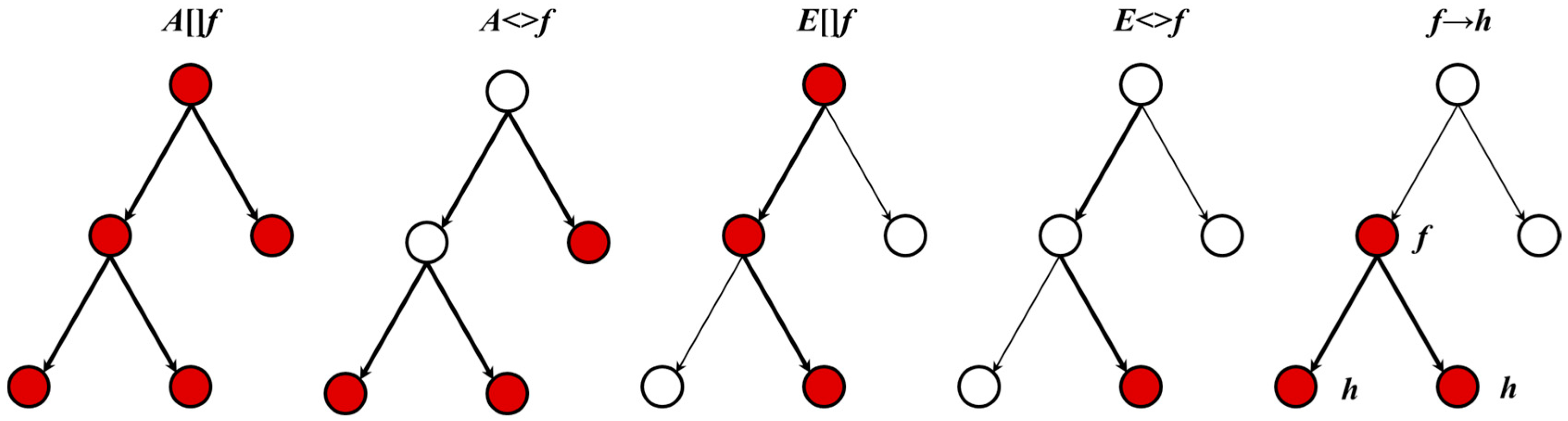
A indicates that for a given property, all paths in the model are satisfied. E indicates that for a given property, at least one path in the model can be satisfied. <> and [] are used to quantify the status on the path. [] indicates that all states on the desired path can satisfy given properties while <> indicates that at least one state on the desired path can satisfy given properties. Figure 3 illustrates the path formula.
Path formulae can be classified into reachability, safety, and liveness (As illustrated in Table 2). Reachability properties ask whether for a given φ , there exists a path starting at the initial state, such that φ is eventually satisfied along that path. Reachability properties do not by themselves guarantee the correctness of the system, but they validate the basic behavior of the model. Safety properties ask whether a bad result will never happen, or an awaited result is invariantly true. Liveness properties are of the form “an awaited result will eventually happen”. With this type of properties, response conditions can be verified as follows “whenever ϕ is satisfied, eventually φ will be satisfied”.
In addition, UPPAAL supports urgent locations (marked as ‘u’) and committed locations (marked as ‘c’). In the urgent locations, time may not progress, but interleavings with normal states are allowed. A committed location is more restrictive: delay is not allowed, and the committed location must be left in the successor state. The synchronization mechanism in UPPAAL is a hand-shaking synchronization: two processes take a transition at the same time in the synchronization channel ch, one will have a ch! and the other ch?
For direct use in the UPPAAL model-checker, the formal specification and verification of the behaviors can be executed according to the following steps:
(1)
Modeling timed automata of the intended behavior
(2)
Describing the intended behavior in natural language.
(3)
Formalizing the informal behavior by using a subset of TCTL.
(4)
Translating the behavior properties into the input language permitted by UPPAAL and executing the formal verification.

4.3. The Formal Specification and Verification of the UEMS

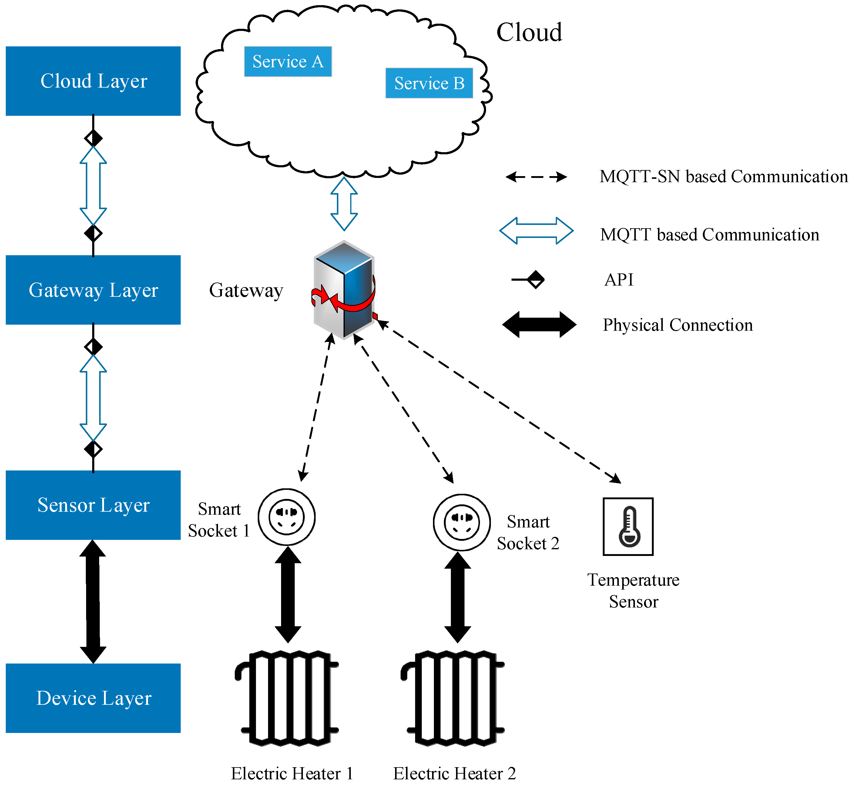
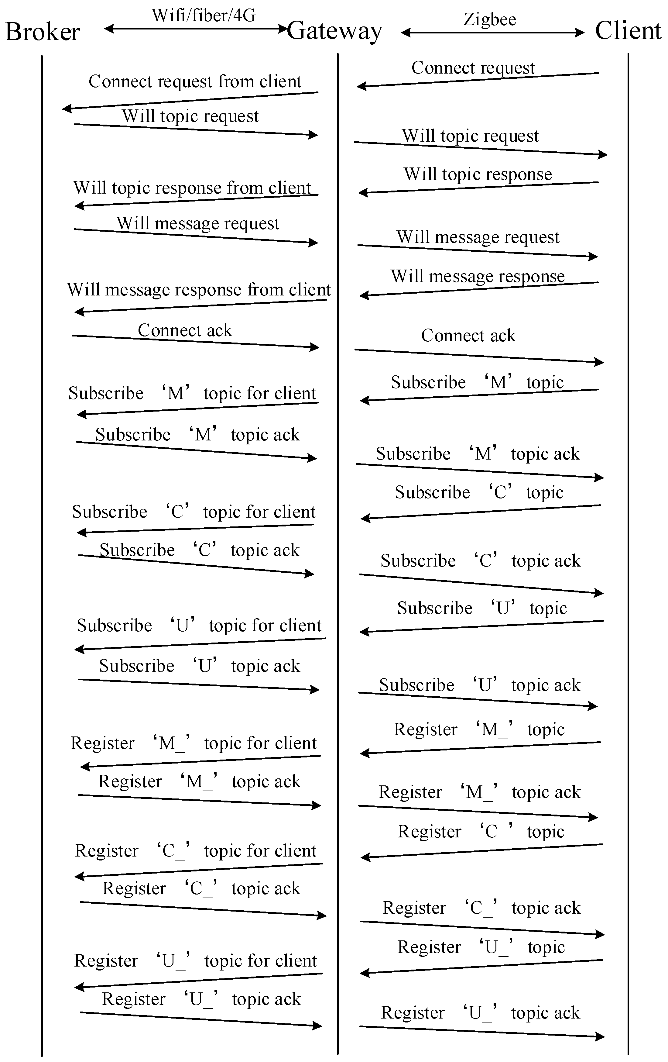
(1) Connection behavior. In the MQTTSN-based UEMS, an intelligent terminal is regarded as a client and needs to setup a connection to a gateway before it can exchange information with that gateway. The procedure of setting up a connection with a gateway is illustrated in Figure 3, in which it is assumed that the client requests the gateway to prompt for the transfer of Will topic and Will message. This request is indicated by setting the Will flag of the CONNECT message. The terminal then sends these two pieces of information to the gateway upon receiving the corresponding request messages WILLTOPICREQ and WILLMSGREQ. The procedure is terminated with the ACK message of register ‘U_’ topic sent by the gateway. Table 3 introduces the meaning of topics in Figure 4.
It should be noted that the upper half part of Figure 4 is the standard connection procedure of MQTT-SN while the lower half part, which includes topic subscription of ‘M’, ‘C’ and ‘U’ and topic registration of ‘M_’, ‘C_’ and ‘U_’, is our originality. Those basic topics are based on the major behaviors of intelligent terminals in the UEMS, which have been mentioned in Section 3.3. The proposed basic topics could help topic-oriented MQTT-SN avoid hidden troubles such as topic explosion.
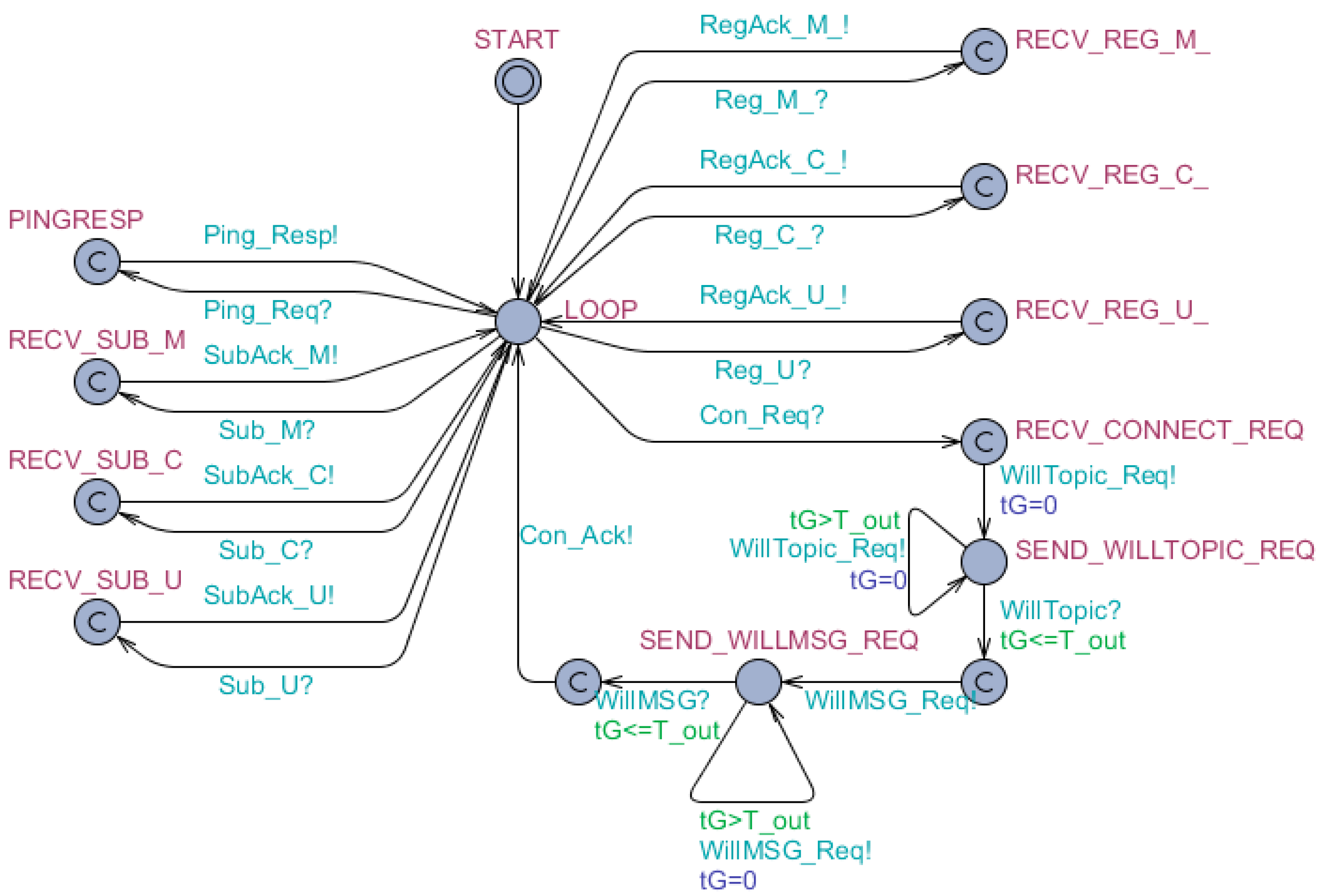
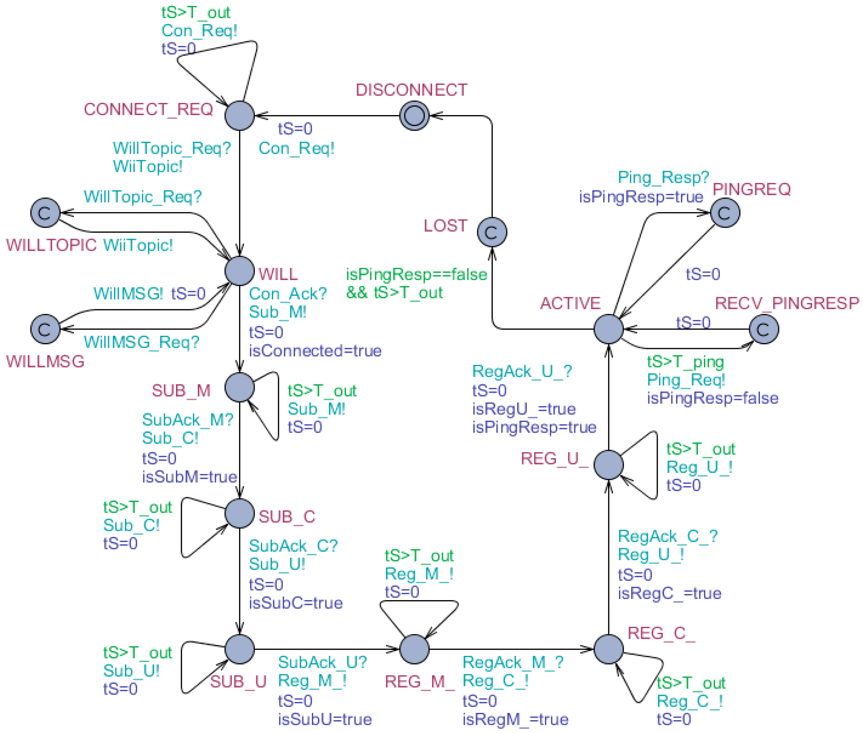
The formal specification of connection behavior based on timed automata model is depicted as Figure 5 and Figure 6 (where the subscriber is instantiated as Gw and the publisher is instantiated as Sck). Figure 5 and Figure 6 are formal specifications of Figure 4, i.e., the connection behavior of intelligent terminals. After sending connecting request, a Sck would successively subscribe the ‘M’ topic, subscribe the ‘C’ topic, subscribe the ‘U’ topic, register the ‘M_’ topic, register the ‘C_’ topic, and register the ‘U_’ topic to a Gw. Additionally, some other details are added into Figure 5 and Figure 6 to make the behavior more realistic. For example, the ping mechanism is introduced. When the Sck is active, it would send a ‘Ping_Req’ message within each predefined time period, which the Gw acknowledges with a ‘Ping_Resp’ message immediately. If the Sck does not receive a ‘Ping_Resp’ message within a predefined latency time, it will go into lost state and try to reconnect the Gw.
The formal verifications of the time automata are illustrated in Table 4.
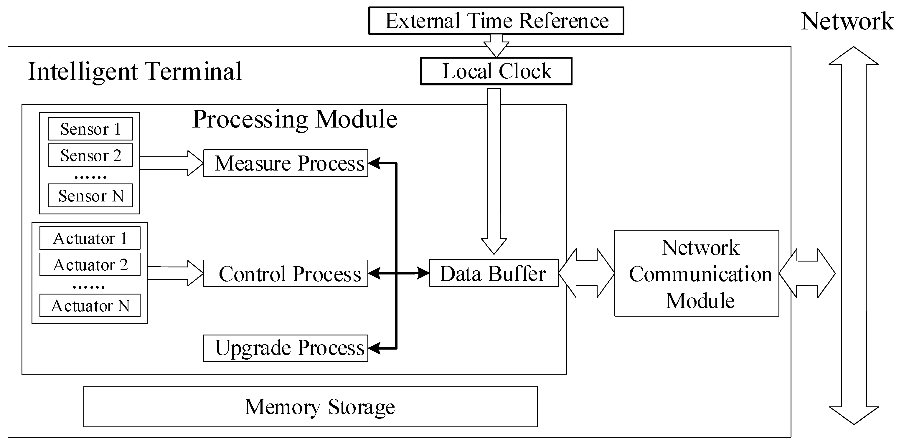
(2) Measure behavior. Monitoring various signals of a physical device is imperative in CPS. The more timely and frequent the data publishing is, the more precise and synchronized the virtual mirror of physical processing established in the computing system is.
The normal approach is to sample the signals equidistant in time which is called Riemann sampling. However, the communication network of UEMS is usually the resource limited and unstable WSNs. The gateway, which is the message transfer station between the cloud server and the intelligent terminals, bears considerable information throughput. It is crystal clear that an increase of the number of nodes and communication traffic will inevitably heavier the burden of the network and further cause the instability of the network.
To improve data exchange efficiency, a data sampling and publishing mechanism based on Lebesgue sampling [22], which samples the system when the output has changed with a specified amount, is adopted in this paper.
The hybrid model of the proposed data exchange mechanism is illustrated in Figure 7.
Where t is current time and t is the time of last data publishing. W ( x ( t ) ) denotes a vector of monitoring data types of device at time t :
W ( t ) = [ s 1 ( t ) , s 2 ( t ) s n ( t ) ]
where s i ( t ) denotes the value of the ith monitoring data types at time x ( t ) .
And Δ is the vector of the predefined threshold of the monitoring data type:
Δ = [ δ s 1 , δ s 2 , δ s n ]
where δ s i is the predefined threshold of the monitoring data type s i ,   ( i = 1 , 2 , n ) .
For example, if the power, current and voltage of an electric heater are the three monitoring data types, W ( t ) could be defined as [ p o w e r ( t ) ,   c u r r e n t ( t ) , v o l t a g e ( t ) ] , which implies that s 1 is power, s 2 is current and s 3 is voltage.
The hybrid model has two states, ‘Data Sampling’ and ‘Data Publishing’. ‘Data Sampling’ state only samples concerned data and does not publish them while ‘Data Publishing’ state delivers the sampled data to certain receiver such as gateway. These two states can be transformed into each other when certain condition is satisfied:
(1)
If current state is ‘Data Sampling’, the state will transform into ‘Data Publishing’ when the deviation between current sampled value and the sampled value of last ‘Data Publishing’ of any monitoring data type is greater than the predefined threshold, that is, | s i ( t ) s i ( t ) | > δ s i ,   i = 1 ,   2 ,   3 n . If the condition is not satisfied, ‘Data Sampling’ state will be maintained.
(2)
If current state is ‘Data Publishing’, the state will transform into ‘Data Sampling’ when the deviations between current sampled value and the sampled value of last ‘Data Publishing’ of all monitoring data types are no more than the predefined threshold, that is, | W ( t ) W ( t ) | . If the condition is not satisfied, ‘Data Publishing’ state will be maintained. Additionally, once the state is transformed into ‘Data Publishing’, t will be updated to be t .
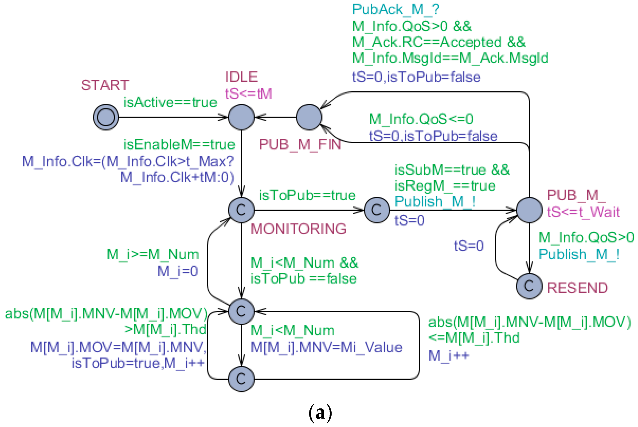
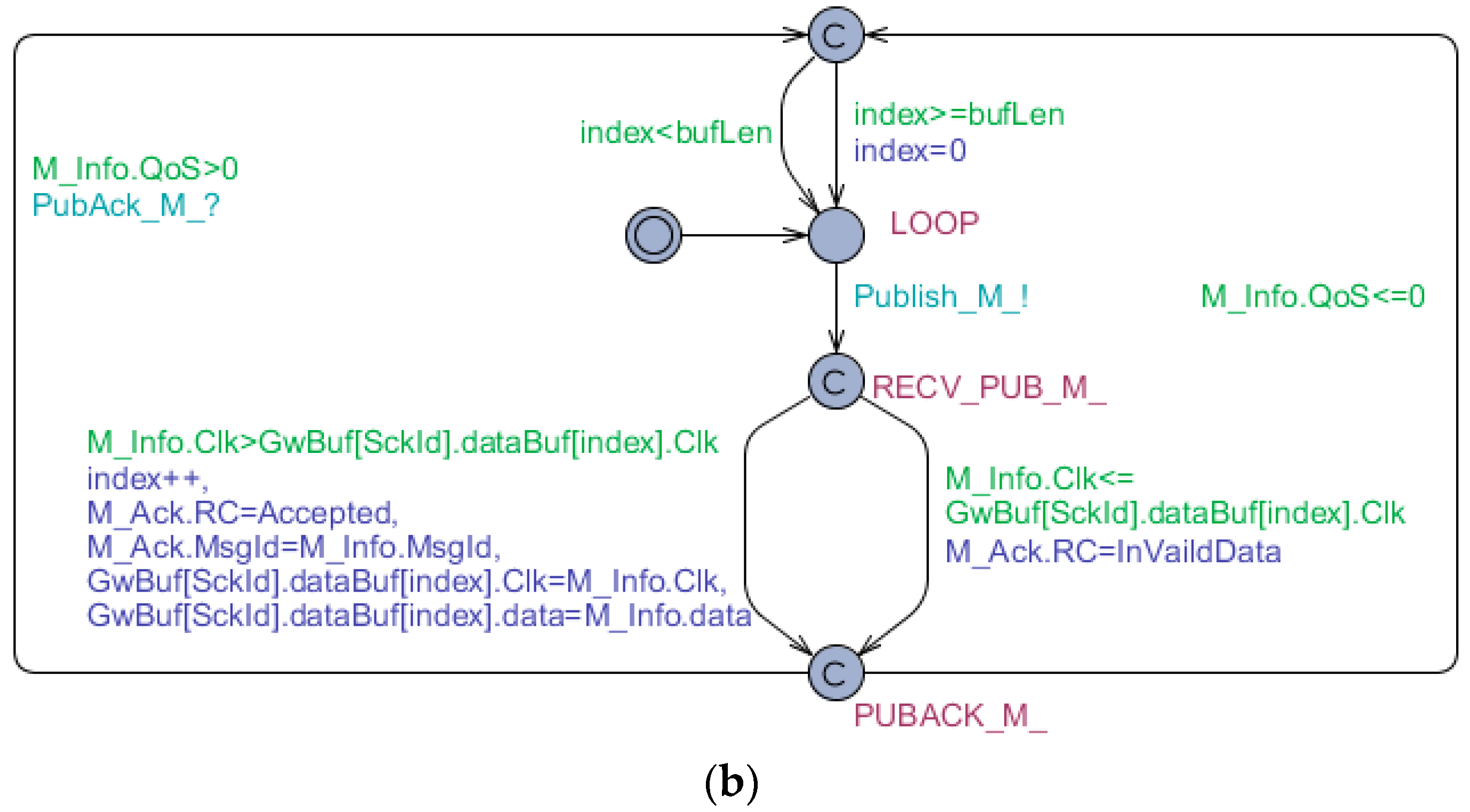
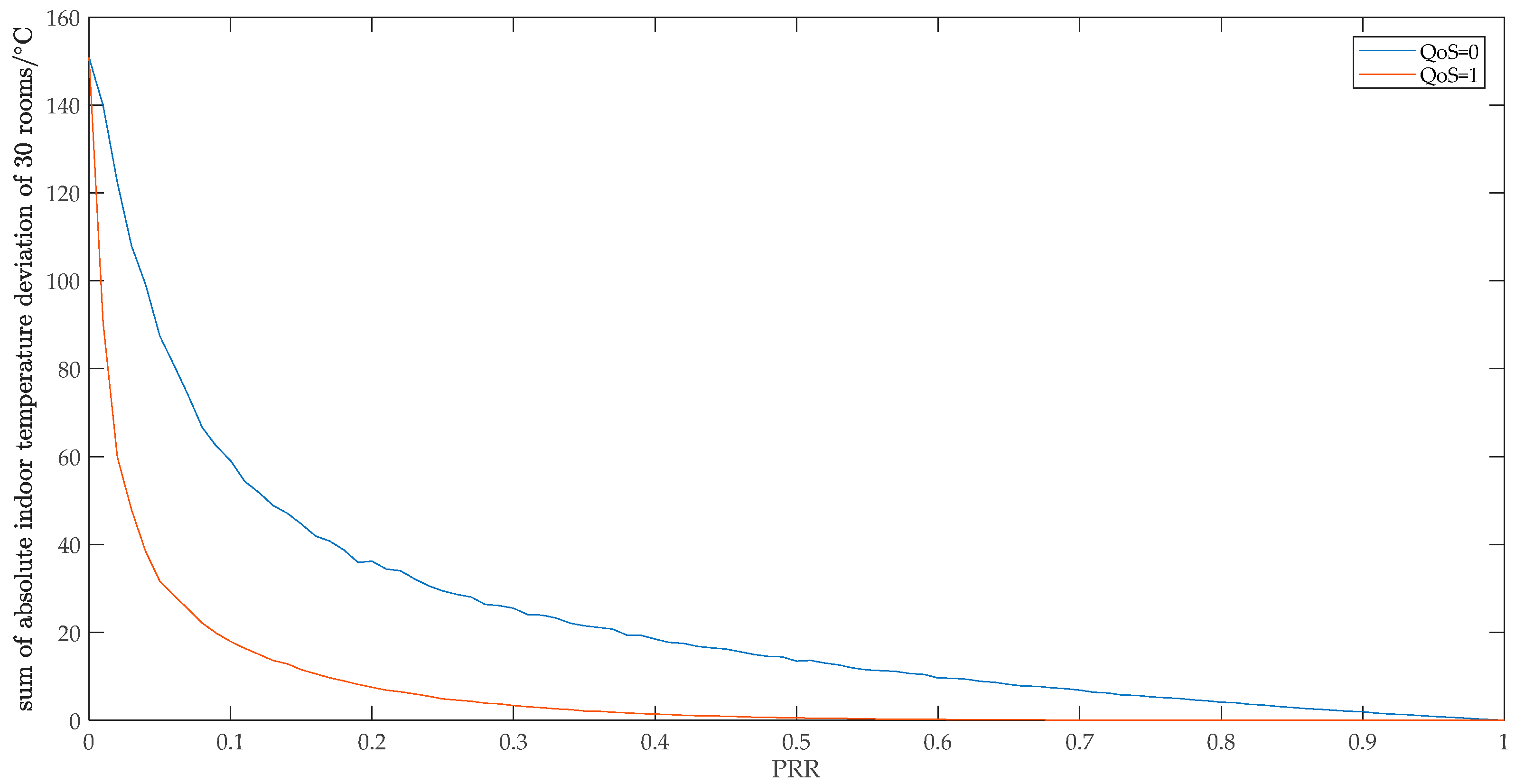
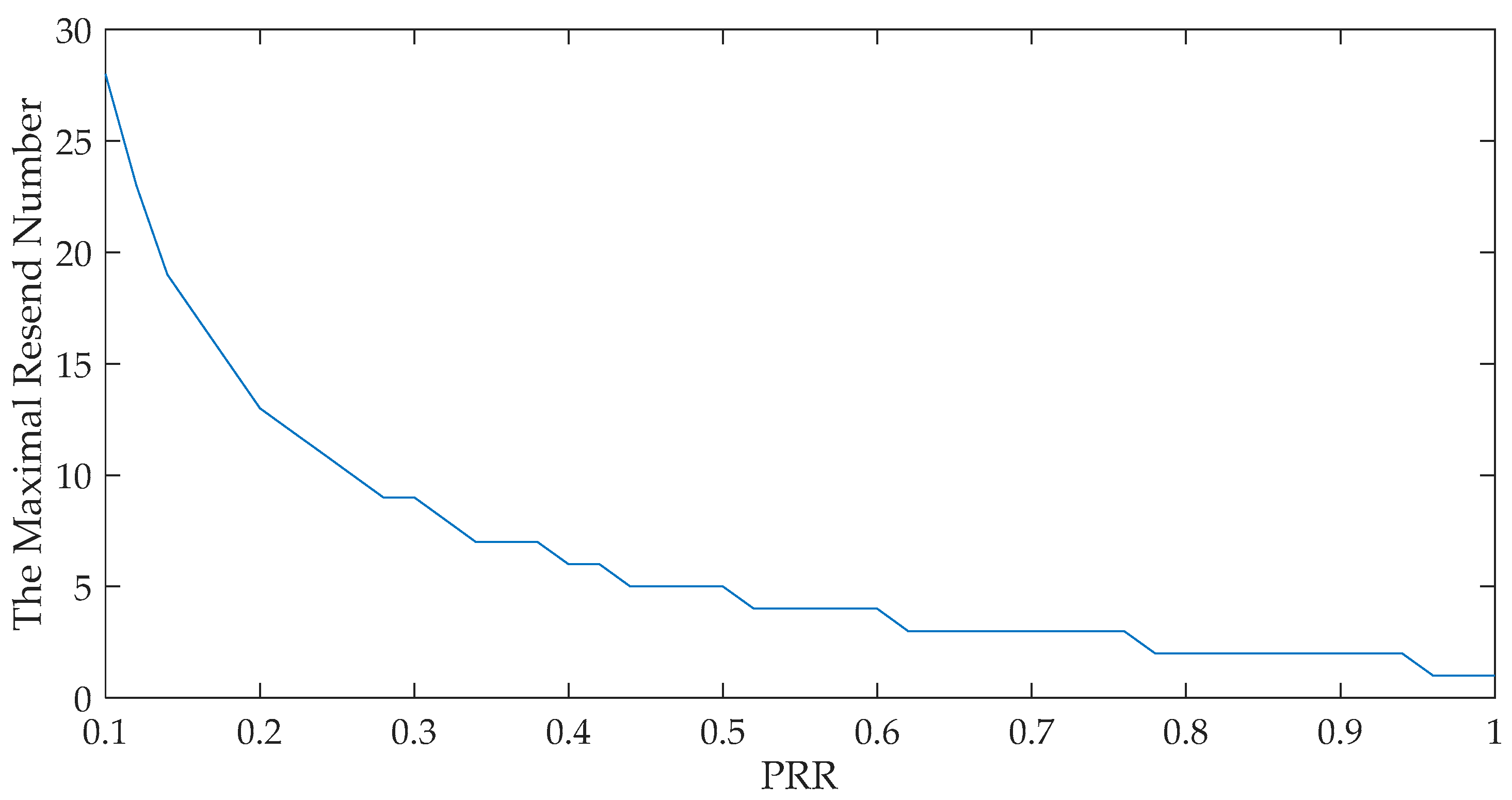
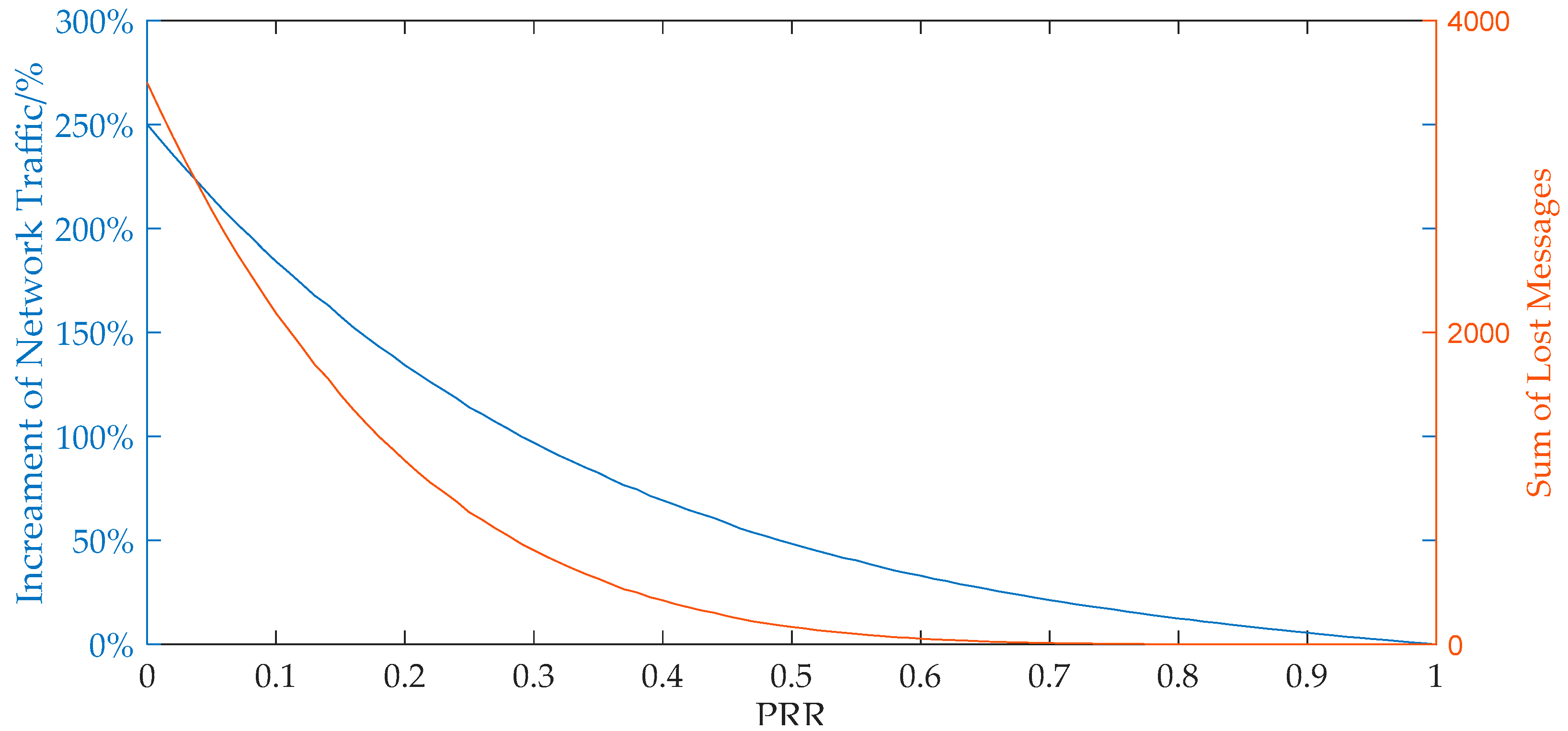
Figure 8 illustrates the formal specification of the measure behavior based on the timed automata model (where the publisher is instantiated as Sck and the subscriber is instantiated as Gw). The Sck applies the above-mentioned data exchange mechanism to decide whether the sampled data should be published. Some other details are also introduced to make the behavior more realistic. For example, the Sck would resend the sampled data until it receives a ‘PubAck_M_’ message in the condition of QoS > 0. In addition, each measurement message has a time mark. When the Gw receives a measurement message, it will check the message’s time mark with the last measurement message of the same Sck. If the former is less than the later, the message will be judged as invalid data.
The formal verifications of the time automata are illustrated in Table 5.
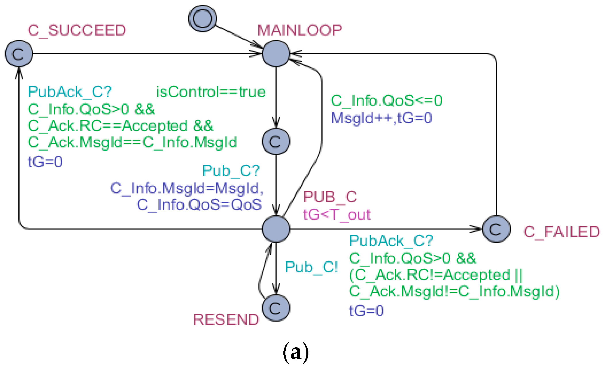
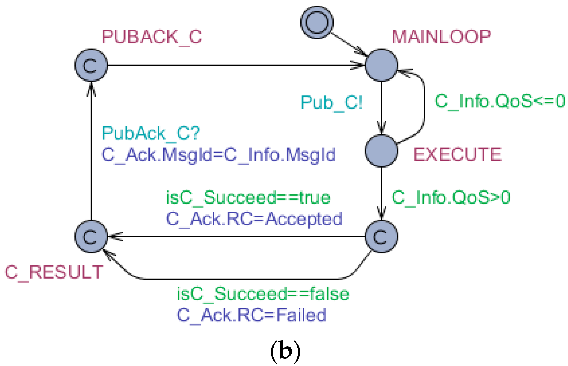
(3) Control behavior. The control messages have high priority and real-time requirements. The QoS of the message is always set 1 or 2, which ensures that the message arrives at the receiver at least one time. In addition, the receiver must respond with an ACK message. The formal specifications of the control behavior based on timed automata model are depicted as Figure 9 (where the publisher is instantiated as Gw and the subscriber is instantiated as Sck). Similar to measure behavior, the Gw would resend the control command until it receives a ‘PubAck_C’ message in the condition of QoS > 0. In the condition of QoS > 0, the response message of Sck should explicitly indicate the execution result of the control so that the Gw could know whether the control is successful.
The formal verifications of the time automata are illustrated in Table 6.
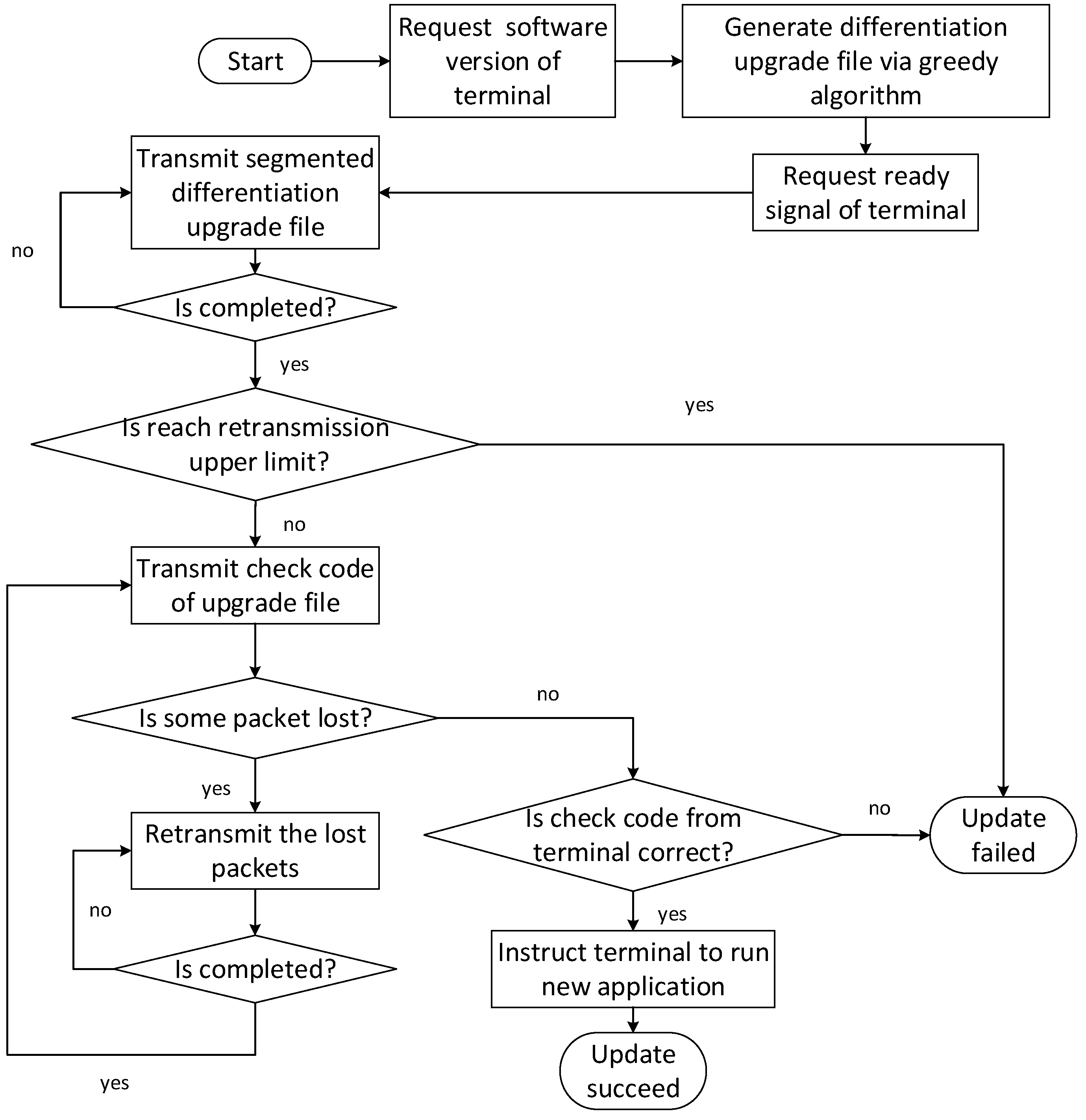
(4) Upgrade behavior. To further support scalability of intelligent terminals, remote firmware upgrade is implemented to expand and update the functions of modules or devices.
Since the UEMS in this paper is based on ZigBee wireless network, which cannot transmit all upgrade data at one delivery, the upgrade file needs to be divided into block data of appropriate length to transmit. In addition, a greedy algorithm is adopted to generate the upgrade file according to the differentiation between the old firmware and the targeted firmware. The process of the remote firmware upgrade is depicted in Figure 10.
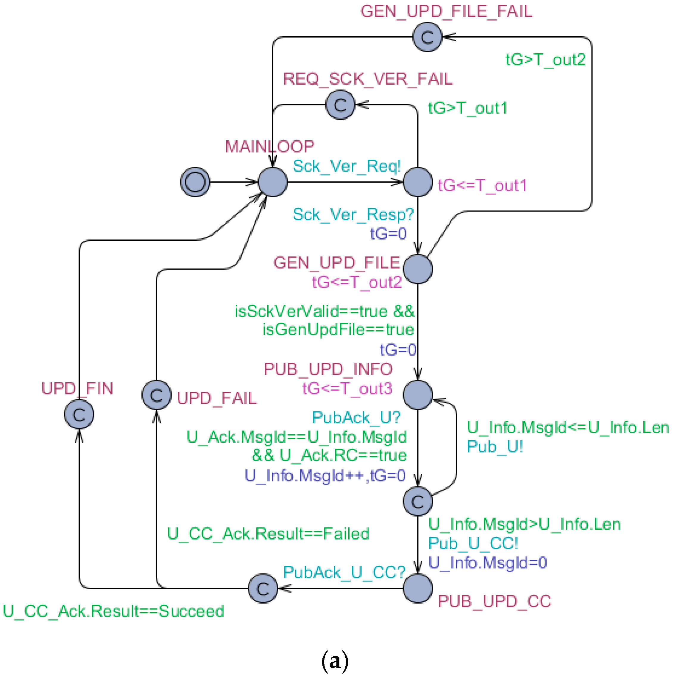
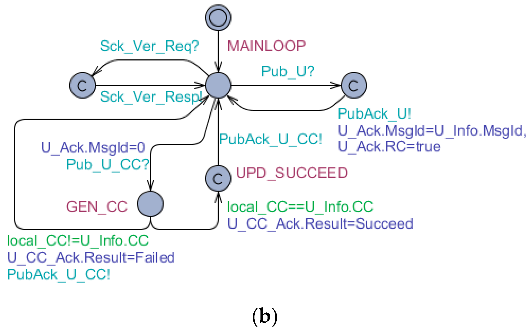
The formal specifications of upgrade behavior based on timed automata model are depicted as Figure 11 (where the publisher is instantiated as Gw and the subscriber is instantiated as Sck). As illustrated in Figure 10, to generate the upgrade file, the Gw would firstly request the software version of the Sck. After the Sck returns the version information and is ready for upgrade, the Gw starts to transmit segmented upgrade file. After the transmission of upgrade file is completed, the Gw would deliver a check code of the upgrade file to the Sck. The Sck would then check the received check code with the local check code. If the two check codes are equivalent, the upgrade of the Sck is successful.
The formal verifications of the time automata are illustrated in Table 7.

5. The Cyber-Physical Performance Evaluation of the ADR Control Strategy

In this section, the ADR performances in ideal situation and in real situation are subsequently illustrated, which demonstrates that the ADR control strategy generated without considering cyber-physical interplay would degrade in practical project.
In this heating project, the time interval with comfort demand is from 9:00 a.m. to 16:00 p.m. and the temperature interval of comfort setting is from 16 °C to 20 °C. The price curve as well as outdoor temperature curve is depicted in Figure 12.
In addition, the room layout plan is shown in Figure 13 and the amount of the rooms with electric heater is 30. μ n = 98 % , T l = 16 °C and T h = 20 °C and Δ t is selected to be 5 min. R n , C n are fitted by collected temperature data of several days. The R n , C n and P n are listed in Table A1.

5.1. The ADR Performance in Ideal Situation

Considering the optimization problem is essentially a 0–1 programming problem, MATLAB (MathWorks, Natick, MA, USA) R2017b assisted with GUROBI7.0 (Gurobi, Beaverton, Oregon, USA) is selected as the simulation software while the hardware environment is Dell laptop with i5-3210M CPU and 4GB internal storage. The optimization problem composes of 30 rooms with 120 time slots ( M = T o p t / t = 600 / 5 = 120 ). The computation time is about 10 s, which is acceptable in our problem scenario.
Figure 14 illustrates the ADR performance in the condition of ideal communication and the indoor temperature curves of 30 rooms are mainly in the preset comfort band during 9:00 to 16:00. As a result, the heater of all rooms would be powered off after 16:00 p.m. Because of the thermal interaction between room and outdoor atmosphere, the indoor temperature of all rooms would be equivalent with outdoor temperature at 6:00 a.m. in the next day, i.e., 6 °C. It should be noted that to meet the comfort demand at 9:00 as well as achieve lower cost, heaters are inclined to start to work in advance because of the lower price in early morning. The power consumption is 476.833 kWh per day and the electricity fare is 228.417 RMB per day according to the ADR strategy.

5.2. The ADR Performance Considering Real Communication

In this paper, packet receive rate (PRR), which may be considerably affected by the wireless channel behavior, is introduced as a metric of link quality. The PRR is defined as Equation (6).
PRR = The   number   of   receive   messages The   number   of   send   messages × 100 %
Receive signal strength index (RSSI), link quality index (LQI) and signal noise ratio (SNR) are three indexes belong to the family of hardware-based link quality estimators (LQE) [24]. In the condition of IEEE 802.15.4-compliant wireless communication, several previous studies have revealed that PRR can be approximated by above hardware-based parameters with sigmoid curve (As depicted in Figure 15) [25,26].
Due to sigmoid correlation between LQE and PRR, it is impossible and unnecessary to construct a wireless network of which PRR = 100%. According to our experience, the PRRs of most ZigBee nodes are no more than 95%. Figure 16 and Figure 17 illustrate the ADR performance in the condition of PRR = 95% and PRR = 80% respectively. The simulation of each PRR is performed 50 times. Figure 16a and Figure 17a are the indoor temperature curve of 30 rooms in one of those results. Figure 16b and Figure 17b are standard box plots of the sum of absolute deviation between the desired temperature region and the real indoor temperature of 30 rooms at each timeslot. The red cross can be regarded as the maximal deviation. As we can see, even if PRR = 95%, the violation of comfort band happens occasionally which means that the ADR strategy without consideration of link quality deteriorate significantly in real cyber-physical scenario.
Power consumption and electricity fare of the ADR strategy from PRR = 50% to PRR = 100% are respectively presented as box plots in Figure 18a,b (the simulation of each PRR is executed 50 times). As shown in Figure 16, Figure 17 and Figure 18, unstable communication exacerbates the ADR strategy performance, that is, not only user comfort cannot be ensured but also electricity fare increases.

5.3. The QoS-Based Approach for ADR Performance Improvement in Real Communication

The previous simulations have illustrated the impact of communication reliability on the proposed ADR control strategy. Even in a pretty good communication scenario such as PRR = 95%, the performance degradation of the ADR control strategy still occurs. One of the practical solutions is taking communication reliability into consideration while designing the ADR control strategy. However, a more cost-effective solution is to utilize the QoS mechanism provided by MQTT/MQTT-SN.
Figure 19 compares the sum of absolute indoor temperature deviation of 30 rooms of QoS = 0 and QoS = 1. As mentioned earlier, QoS = 0 means that sender just transmits a message for one time and whether receiver receives the message or not is not the concern of the sender. QoS = 1 means that the sender will retransmits a message until it receives a respond from the receiver or reaches the maximal resend number. In Figure 19, the maximal resend number is 5.
Figure 20 illustrates the maximal resend numbers when the sum of absolute indoor temperature deviation of 30 rooms is required less than 1 °C.
Although the QoS-based approach could significantly improve the effect of the ADR control strategy, it essentially makes a trade-off between communication reliability and communication traffic. As illustrated in Figure 21, when PRR = 50%, the network traffic grows 50%. It should be noted that the network congestion caused by the retransmissions of QoS = 1 will further reduce the PRR in return.

6. Conclusions

In this paper, the interdependence and interplay between the cyber system and the physical system of the UEMS for the ADR control strategy is analyzed. The MQTT/MQTT-SN-based UEMS is firstly proposed and the major behaviors of intelligent terminals in the UEMS are abstracted. Subsequently, a UPPAAL-based methodology of the formal specification and verification for the abstract behaviors is also proposed. The case studies have illustrated the impact of communication reliability on the proposed ADR control strategy. Although QoS-based mechanism provided by MQTT/MQTT-SN has been demonstrated as a cost-effective solution for the ADR control strategy under unreliable communication, the QoS-based mechanism may result in network congestion due to its verbose retransmissions.

Author Contributions

K.J. and G.H. conceived and designed the experiments; K.J. and S.F. performed the experiments; K.J. and J.X. analyzed the data; S.F. contributed analysis tools; K.J. wrote the paper.

Funding

This research received no external funding.

Conflicts of Interest

The authors declare no conflicts of interest.

Appendix A

Table A1. The R, C and P of 30 rooms.
Room No.R (°C/W)C (J/°C)P (W)
10.008053004.52000
20.0080075,196.66000
30.0080275,566.26000
40.0080675,331.86000
50.0080675,269.46000
60.0080575,296.06000
70.0080475,528.06000
80.008033010.52000
90.008023012.72000
100.008073005.92000
110.008073012.92000
120.008063011.72000
130.008063011.92000
140.008033022.72000
150.008063006.52000
160.008033028.52000
170.0080475,503.46000
180.008063025.02000
190.008073005.02000
200.00804151,484.812,000
210.008053026.52000
220.00802195,301.818,000
230.0080675,305.26000
240.0080675,619.26000
250.008043009.62000
260.008013002.72000
270.0080575,102.26000
280.0080275,371.46000
290.0080175,371.36000
300.00807150,082.512,000

References

  1. Rajkumar, R.; Lee, I.; Sha, L.; Stankovic, J. Cyber-physical systems: The nextcomputing revolution. In Proceedings of the DAC’10 47th Design Automation Conference, Anaheim, CA, USA, 13–18 June 2010; pp. 731–736. [Google Scholar]
  2. Dong, L.; Sheng, W.; Yun, W.; Wang, Y. Key Technologies and Trends of Cyber Physical System for Power Grid. Proc. CSEE 2015, 35, 3522–3531. [Google Scholar]
  3. Muratori, M.; Rizzoni, G. Residential demand response: Dynamic energy management and time-varying electricity pricing. IEEE Trans. Power Syst. 2016, 31, 1108–1117. [Google Scholar] [CrossRef]
  4. Zhang, D.; Li, S.; Sun, M.; O’Neill, Z. An Optimal and Learning-Based Demand Response and Home Energy Management System. IEEE Trans. Smart Grid 2016, 7, 1790–1801. [Google Scholar] [CrossRef]
  5. Wen, Z.; O’Neill, D.; Maei, H. Optimal demand response using device-based reinforcement learning. IEEE Trans. Smart Grid 2015, 6, 2312–2324. [Google Scholar] [CrossRef]
  6. Hansen, T.; Chong, E.; Suryanarayanan, S.; Hansen, T.; Chong, E.; Suryanarayanan, S. A Partially Observable Markov Decision Process Approach to Residential Home Energy Management. IEEE Trans. Smart Grid 2018, 9, 1271–1281. [Google Scholar] [CrossRef]
  7. Erol-Kantarci, M.; Mouftah, H.T. Wireless sensor networks for cost-efficient residential energy management in the smart grid. IEEE Trans. Smart Grid 2011, 2, 314–325. [Google Scholar] [CrossRef]
  8. Zheng, L.; Lu, N.; Cai, L. Reliable wireless communication networks for demand response control. IEEE Trans. Smart Grid 2013, 4, 133–140. [Google Scholar] [CrossRef]
  9. Sa, J.L.P.D.; Cartaxo, R. Implementing Substations Automatic Control Functions Designed with Petri Nets on IEC 61850. IEEE Trans. Power Deliv. 2011, 26, 1119–1127. [Google Scholar]
  10. Zhang, Q.; Wang, X.; Du, S.; Zhao, S. Formal specification and verification of intelligent electronic device interaction model based on IEC 61850. Autom. Electr. Power Syst. 2012, 36, 72–76. [Google Scholar]
  11. Xiong, H.; Zhu, Y.; Fan, Z.; Zhang, F.; Wang, D.; Shi, L. Formal Specification and Verification of IEC 61850 IED Interoperability Based on Behavior Tree. Autom. Electr. Power Syst. 2013, 37, 66–71. [Google Scholar]
  12. Hartmanns, A.; Hermanns, H. Modelling and decentralised runtime control of self-stabilising power micro grids. In International Symposium on Leveraging Applications of Formal Methods, Verification and Validation; Springer: Berlin/Heidelberg, Germany, 2012; pp. 420–439. [Google Scholar]
  13. Sugumar, G.; Selvamuthukumaran, R.; Dragicevic, T.; Nyman, U.; Larsen, K.G.; Blaabjerg, F. Formal validation of supervisory energy management systems for microgrids. In Proceedings of the IECON 2017—43rd Annual Conference of the IEEE Industrial Electronics Society, Beijing, China, 29 October–1 November 2017; pp. 1154–1159. [Google Scholar]
  14. Lu, N. An evaluation of the HVAC load potential for providing load balancing service. IEEE Trans. Smart Grid 2012, 3, 1263–1270. [Google Scholar] [CrossRef]
  15. Stanford-Clark, A.; Truong, H.L. MQTT for Sensor Networks (MQTT-SN) Protocol Specification Version 1.2. 2008. Available online: http://mqtt.org/new/wp-content/uploads/2009/06/MQTT-SN_spec_v1.2.pdf (accessed on 17 June 2018).
  16. Cintuglu, M.H.; Youssef, T.; Mohammed, O.A. Development and application of a real-time testbed for multiagent system interoperability: A case study on hierarchical microgridcontrol. IEEE Trans. Smart Grid 2016, 9, 1759–1768. [Google Scholar] [CrossRef]
  17. Kumar, K.; Radhakrishnan, M.; Sivalingam, K.M.; Deva, P.; Karthick, S.K. Comparison of publish-subscribe network architectures for smart grid wide area monitoring. In Proceedings of the 2012 IEEE Third International Conference on Smart Grid Communications (SmartGridComm), Tainan, Taiwan, 5–8 November 2012; pp. 611–616. [Google Scholar]
  18. Rathod, P.; Sharma, D.; Golhani, A. A topic-based publish-subscribe message broker for SCADA system using hierarchical subscription handling. In Proceedings of the 2017 International Conference on Advances in Computing, Communication and Control (ICAC3), Mumbai, India, 1–2 December 2017; pp. 1–10. [Google Scholar]
  19. Starke, M.; Herron, A.; King, D.; Xue, Y. Implementation of a Publish-Subscribe Protocol in Microgrid Islanding and Resynchronization with Self-Discovery. IEEE Trans. Smart Grid 2017. [Google Scholar] [CrossRef]
  20. Hastings, J.C.; Laverty, D.M. Modernizing wide-area grid communications for distributed energy resource applications using MQTT publish-subscribe protocol. In Proceedings of the 2017 IEEE Power & Energy Society General Meeting, Chicago, IL, USA, 16–20 July 2017; pp. 1–5. [Google Scholar]
  21. Bengtsson, J.; Yi, W. Timed Automata: Semantics, Algorithms and Tools. Lect. Notes Comput. Sci. 2004, 3098, 87–124. [Google Scholar] [Green Version]
  22. Jia, K.; He, G. Research of Smart Electric Appliance Network Data Collection and Communication Mechanism. Proc. CSEE 2016, 36, 1544–1551. [Google Scholar]
  23. Fan, S.; Jia, K.; Guo, B.; Jiang, L.; Wang, Z.; He, G. Collaborative Optimal Operation Strategy for Decentralized Electric Heating Loads. Autom. Electr. Power Syst. 2017, 41, 20–29. [Google Scholar]
  24. Xu, L.; Lillis, D.; Collier, R.M.; O’Hare, G.M.P. A User Configurable Metric for Clustering in Wireless Sensor Networks. In Proceedings of the 3rd International Conference on Sensor Networks (SENSORNETS 2014), Lisbon, Portugal, 7–9 January 2014; pp. 221–226. [Google Scholar]
  25. Srinivasan, K.; Dutta, P.; Tavakoli, A.; Levis, P. An empirical study of low-power wireless. ACM Trans. Sens. Netw. (TOSN) 2010, 6, 16. [Google Scholar] [CrossRef]
  26. Wei, S. Research on Wireless Sensor Networks with QoS for Smart Distribution Grid Communication Application; Hefei University of Technology: Hefei, China, 2012. [Google Scholar]
Figure 1. The architecture of the UEMS.
Applsci 08 01035 g001
Figure 2. A general model for an intelligent terminal.
Applsci 08 01035 g002
Figure 3. The path formulae of the query language in UPPAAL.
Applsci 08 01035 g003
Figure 4. The connect procedure of the MQTTSN-based communication protocol.
Applsci 08 01035 g004
Figure 5. Timed automata model of connect message subscriber.
Applsci 08 01035 g005
Figure 6. Timed automata model of connect message publisher.
Applsci 08 01035 g006
Figure 7. The hybrid model of the proposed data exchange mechanism.
Applsci 08 01035 g007
Figure 8. Timed automata model of measure message: (a) publisher; (b) subscriber.
Applsci 08 01035 g008aApplsci 08 01035 g008b
Figure 9. Timed automata model of control message: (a) publisher; (b) subscriber.
Applsci 08 01035 g009aApplsci 08 01035 g009b
Figure 10. The flow of remote firmware upgrade.
Applsci 08 01035 g010
Figure 11. Timed automata model of upgrade message: (a) publisher; (b) subscriber.
Applsci 08 01035 g011aApplsci 08 01035 g011b
Figure 12. The curve of electricity price and outdoor temperature [23].
Applsci 08 01035 g012
Figure 13. The layout plan of rooms.
Applsci 08 01035 g013
Figure 14. The indoor temperature curve of 30 rooms with ideal communication.
Applsci 08 01035 g014
Figure 15. The correlation between RSSI and PRR (95% confidence level) [26].
Applsci 08 01035 g015
Figure 16. The ADR performance of PRR = 95%: (a) The indoor temperature curve of 30 rooms; (b) The absolute deviation between the desired temperature region and the real temperature.
Applsci 08 01035 g016
Figure 17. The ADR performance of PRR = 80%: (a) The indoor temperature curve of 30 rooms; (b) The absolute deviation between the desired temperature region and the real temperature.
Applsci 08 01035 g017
Figure 18. The ADR performance from PRR = 50% to PRR = 100%: (a) Power consumption; (b) Electricity fare.
Applsci 08 01035 g018
Figure 19. The sum of absolute indoor temperature deviation of 30 rooms of QoS = 0 and QoS = 1.
Applsci 08 01035 g019
Figure 20. The maximal resend numbers when the sum of absolute indoor temperature deviation of 30 rooms is required less than 1 °C.
Applsci 08 01035 g020
Figure 21. The sum of messages and the sum of lost messages in various PRRs (QoS = 1, maximal resend number is 5).
Applsci 08 01035 g021
Table 1. The definition of QoS level in MQTT-SN.
QoSSemanticDescription
−1At most one delivery.The messages are connectionless. No response is sent by the receiver and no retry is performed by the sender
0At most one delivery.The sender has been connected to the receiver. The message arrives at the receiver either once or not at all. No response is sent by the receiver and no retry is performed by the sender
1At least one delivery.The sender has been connected to the receiver. This quality of service ensures that the message arrives at the receiver at least once. The receiver must respond with an ACK message
2Exactly one delivery.The sender has been connected to the receiver. This is the highest quality of service, for use when neither loss nor duplication of messages acceptable
Table 2. The description of query language in UPPAAL.
ClassificationFormal SpecificationDescription
reachabilityE<>fThere exists a path where f eventually holds.
safetyA[]fFor all paths f always holds.
E[]fThere exists a path where f always holds.
livenessA<>fFor all paths f will eventually hold.
F→hWhenever f holds h will eventually hold.
Table 3. The subdivided behaviors of the UEMS.
TopicDescription of Behavior
MMeasure request from gateway
CControl request from gateway
UUpdate request from gateway
M_Measure result from terminal
C_Control result from terminal
U_Update result from terminal
Table 4. The formal verifications of the connect behavior.
Formal DescriptionInformal DescriptionResult
E<>Sck.ACTIVEVerify if the terminal can eventually finish connection in some condition.PASS
A[]Sck.LOST imply isPingResp == false and tS > T_outVerify if the terminal gets into lost state when it does not receive a response of heartbeat within the prescribed timePASS
A[]Sck.ACTIVE imply (isConnected == true and isSubM == true and isSubC == true and isSubU == true and isRegM_ == true and isRegC_ == true and isRegU_ == true)Verify if the terminal finishes the connection in the condition of completing subscription and registrationPASS
Table 5. The formal verifications of the measure behavior.
Formal SpecificationInformal DescriptionResult
E<>Sck.PUB_M_Verify if the measure can be eventually triggered in some condition.PASS
A[]Sck.MONITORING imply isActive == true and isEnableM == trueVerify if the terminal gets into monitoring state in the condition that it finished connection and measure function is enable.PASS
A[]Sck.PUB_M_ imply isToPub == true and isSubM == true and isRegM_ == trueVerify if the terminal publishes measure information when the sampling data breaks the threshold. PASS
A[] Sck.PUB_M_FIN imply (M_Info.QoS > 0 and M_Ack.RC == Accepted and M_Info.MsgId == M_Ack.MsgId) or M_Info.QoS ≤ 0Verify if the terminal finishes publish process when QoS ≤ 0 or receiving correct ACK when QoS > 0.PASS
Table 6. The formal verifications of the control behavior.
Formal SpecificationInformal DescriptionResult
A[]Gw.C_SUCCEED imply C_Info.QoS > 0 and C_Ack.RC == Accepted and C_Ack.MsgId == C_Info.MsgIdVerify if the control is successful when the publisher receives correct ACK message including ‘Accepted’ return code and the identical‘MsgId’.PASS
A[]Sck.PUBACK_C imply C_Info.QoS > 0Verify if the subscriber responds to the control when QoS > 0.PASS
A[]Gw.RESEND imply Gw.tG>T_outand C_Info.QoS > 0Verify if the publisher resends control message that QoS > 0 when it does not receive correct ACK during allowed time. PASS
Table 7. The formal verifications of the upgrade behavior.
Formal SpecificationInformal DescriptionResult
E<>Gw.UPD_FINVerify if the upgrade success can be eventually achieved in some condition.PASS
A[]Gw.PUB_UPD_INFO imply U_Info.MsgId ≤ U_Info.LenVerify if the publisher keeps publishing upgrade data until all upgrade data have been transmitted.PASS
A[](Gw.UPD_FIN and Sck.UPD_SUCCEED) imply (U_CC_Ack.Result == Succeed and local_CC == U_Info.CC)Verify if the upgrade process is successful when local generated check code of terminal is equal to the value received from the publisher.PASS

