Article

Line Matching Based on Viewpoint-Invariance for Stereo Wide-Baseline Aerial Images

1
College of Geoscience and Surveying Engineering, China University of Mining &Technology, Beijing 100083, China
2
Key Laboratory of Unmanned Aerial Vehicle Telemetry, Guilin University of Aerospace Technology, Guilin 541004, China
3
Beijing Key Laboratory of Spatial Information Integration and Its Application, Peking University, Beijing 100871, China
4
Advanced Innovation Center for Imaging Technology, Capital Normal University, Beijing 100048, China
*
Authors to whom correspondence should be addressed.
Appl. Sci. 2018, 8(6), 938; https://doi.org/10.3390/app8060938
Submission received: 12 April 2018 / Revised: 28 May 2018 / Accepted: 2 June 2018 / Published: 6 June 2018

Abstract

:
Line matching is the foundation of three-dimensional (3D) outline reconstruction for city buildings in aerial photogrammetry. Many existing studies have good line matching effects when dealing with aerial images with short baselines and small viewing angles. However, when faced with wide-baseline and large viewing-angle images, the matching effect drops sharply or even fails altogether. This paper deals with an efficient and simple method to achieve better line matching performance by a pair of wide-baseline aerial images, which make use of viewpoint-in variance to conduct line matching in rectified image spaces. Firstly, the perspective transformation relationship between the image plane and the geoid plane can be established from a Positioning and Orientation System (POS). Then, according to perspective projection matrices, two original images are separately rectified to conformal images, whose perspective deformation of large viewing-angle can be eliminated. Finally, the rectified images are used to conduct line matching, and the matched line segments obtained are back-projected to the original images. Four pairs of urban oblique aerial images are used to demonstrate the validity and efficiency of this method. Compared with line matching on original images, the number and the correctness of the matched line segments are greatly improved. Moreover, there is no loss of time efficiency. The proposed method can also be applied to general UAV (Unmanned Aerial Vehicle) aerial photogrammetry and introduced into matching for other geometric features, such as points, circles, curves, etc.

1. Introduction

Oblique photogrammetry is a newly developed technology that can effectively create a three-dimensional (3D) model of a city’s buildings. Compared with conventional aerial images, oblique images have their own processing challenges, especially feature matching, due to their wide baselines and large viewing angles. Many scholars have conducted research on point matching for oblique images and achieved reasonable results. For example, affine scale-invariant feature transform (ASIFT) simulates a series of changes in viewing angle and obtains more matched points in the case of a wide baseline [1]; Xiao et al. used a positioning and orientation system (POS) to obtain attitude angles in order to establish affine invariance and to achieve the matching of oblique images [2]; the method proposed by Tuytelaars et al. is based on matching local affine invariant regions, which provides good results for matching under wide-baseline conditions [3]. However, the characteristics of the line and point are quite different, and processing of the line feature is more complex than the point. Therefore, there is some limitation for the application of line matching. In particular, the length of a line segment is relatively long, so the image area involved is relatively large and wide. In this case, the deformation effect caused by the difference in viewing angles of wide-baseline images is relatively more obvious, making it more difficult to match the line segments. Line matching also provides the basis for achieving 3D structural line reconstruction [4,5]. Since the application of line matching is of great significance [6,7,8,9,10,11], it is very important to solve the problem of line matching for wide-baseline images.
From the similarity matching perspective, the existing line matching methods are mainly divided into two categories: those based on the line segment neighborhood’s photometric information (such as intensity, gradient, color, etc.), and those based on geometric constraints of image features. From the number of line segments used for each matching, it can be further divided into two categories: single line-by-line matching and multiple line-group matching. Wang et al. [12] and López et al. [13] in their experiments, created descriptors for each line segment to respectively match the texture information from the gray value distribution. Fan et al. [14], Jia et al. [15], and Klonis et al. [16] separately established geometric constraints for each line segment and the matched feature points in its neighborhood to achieve a good line matching effect. In addition, Zhang et al. combined the texture representation with geometric constraints for line matching, but their method is prone to failure under low-texture or similar textures [17]. A method based on trifocal tensor is used by Schmid et al. to match lines from three or more images; however, their method demands more constraints, therefore many false matches can be eliminated, which also leads to a high level of complexity of the algorithm [18]. There are also some studies online matching specifically for wide-baseline images; amongst them, Wang et al. used line segment groups to create local descriptors that are robust to affine distortions and non-coplanar surfaces [19]. However, this method is time-consuming, and may fail when it cannot find enough line segments or when textures are not abundant. In contrast, Meltzer and Soatto worked on point-like local affine invariant matching [20], which has a good matching effect for large viewing angles, but which is not good at dealing with non-coplanar and complex 3D-structured scenes. Moreover, the two adjacent line segment methods proposed by Li et al. construct ray-point-ray [21] and line-juncture-line [22] structure descriptors. In this method, structured line segments in the first image are used to match with other structured line segments in the second image, so the robustness is relatively strong, and good matching results are achieved. However, it takes a good deal of time to build a pyramid in this way.
The line matching for oblique images is difficult because the results obtained from a wide-baseline have a large viewing angle difference between the two images to be matched. This difference causes the perspective distortion generated in the same area to be inconsistent, resulting in similarity matching of the corresponding lines’ neighborhoods being very low, or even unable to be matched; as such, the line matching effect decreases. Sun et al. used a camera’s exterior orientation elements and the 3D point cloud to find coplanar 3D points around the line segment to construct a homography matrix. This approach eliminates local perspective distortion, but it requires the precise camera orientation elements and known 3D points in advance [23]. Gao et al. employed a disparity map in rectified image space for stereo aerial images [24]. Considering that a POS device is usually situated on an oblique photogrammetric aerial platform, it can provide the camera with initial exterior orientation elements. Therefore, this article contemplates constructing a perspective transformation matrix by using the camera’s interior and exterior orientation elements in the case of unknown 3D coordinates. Firstly, the original two images are projected onto a new object plane (the geoid) by perspective projection matrices to eliminate perspective geometric distortions (including scale and rotation), and rectified into approximate conformal images. Then, line matching is performed on the conformal images. Finally, the matched line segments are back-projected to the original images, thereby improving the line matching effect of the oblique images. This article investigates the feasibility of the proposed method by comparing it with conventional methods. The proposed method adds two steps (rectification and back-projection) to the conventional method, while other processes are exactly the same.

2. Image Rectification Using a Perspective Transformation Model

When the camera displays a 3D world on a two-dimensional (2D) image plane, the projection matrix is used to achieve dimension reduction. Among various projection types, such as orthogonal projection, parallel projection, perspective projection, etc., perspective projection is the most suitable for human sensory vision. Under the perspective projection model, a rectangular planar object in the object space is projected onto the image plane to become trapezoidal or approximately trapezoidal.
According to the perspective transformation model as described above, when the photograph of the same building is captured by two aerial cameras, the rectangular building structure may present the following three situations, as shown in Figure 1.
It can be seen that the two rectangles in Figure 1a are similar; there is no distortion difference, and they have uniform internal grayscale distribution. However, in Figure 1b, the left rectangle has no deformation, but the right rectangle becomes a trapezoid, and its upper region is compressed while its lower region is stretched. However, in Figure 1c, opposite compression and stretching effects appear in the upper and lower areas of the two rectangles. For the red to-be-matched segments, the two line segments’ neighborhood information is consistent in Figure 1a, and matching is easy. In Figure 1b, right line segment’s neighborhood information changes relative to the left, which will cause a certain degree of matching difficulty. In Figure 1c, the relative changes in the neighborhood information of the two line segments are larger, which will lead to greater matching difficulty.
The oblique camera platform and the method of eliminating the perspective distortion effects are described below.

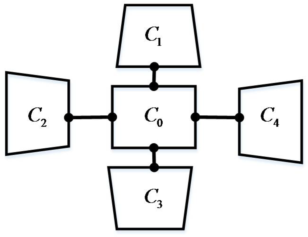
2.1. The Oblique Cameras Structure and the Rotation Matrix Acquisition

The oblique photogrammetric platform selected in this paper contains five cameras. As shown in Figure 2, C 0 is a down-looking camera, whereas C 1 , C 2 , C 3 and C 4 represent four side-looking cameras whose intersection angles with respect to C 0 is 45°.
Using the Y-X-Z rotation system, through a series of conversions with POS data, the three angle elements of the camera, represented by omega( ω ), phi( φ ), kappa( κ ), and three line elements, represented by X S , Y S , Z S , respectively, can be obtained. The camera’s rotation matrix can be expressed as follows:
R = [ r 11 r 12 r 13 r 21 r 22 r 23 r 31 r 32 r 33 ]
where
{ r 11 = cos φ cos κ sin φ sin ω sin κ r 12 = cos φ sin κ sin φ sin ω cos κ r 13 = sin φ cos ω r 21 = cos ω sin κ r 22 = cos ω cos κ r 23 = sin ω r 31 = sin φ cos κ + cos φ sin ω sin κ r 32 = sin φ sin κ + cos φ sin ω cos κ r 33 = cos φ cos ω
Under normal circumstances, on a stable aerial platform, the down-looking camera is approximately vertically projected. Similar to a down-looking camera in conventional aerial photogrammetry, the deformation of acquired down-looking image is very small, but the side-looking images show trapezoidal deformation.

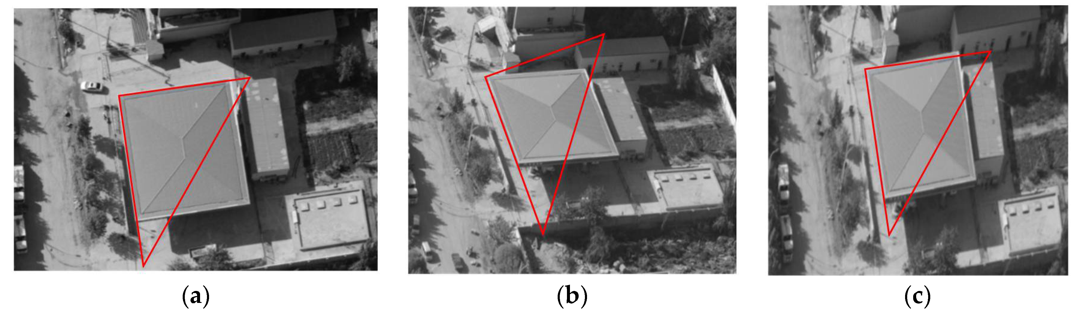
2.2. Perspective Transformation Matrix’s Solution and Image Correction

According to the central perspective projection model in computer vision, the relationship of digital conversion between image points and 3D points in the object space is related by the projection matrix P [25]:
λ x ˜ = P X ˜ = K [ R c | t ] X ˜ = K [ R c | - R c C ] X ˜
where x ˜ = [ u , v , 1 ] T and X ˜ = [ X , Y , Z , 1 ] T are the homogeneous coordinate expressions of the pixel points on the image plane and the corresponding 3D points, respectively, and λ is a constant. K is the camera’s intrinsic parameters matrix, in which units of the focal length f and the image principal points ( x 0 , y 0 ) are all expressed by pixel. R c is the rotation matrix in computer vision, whose Z axis is opposite of that in the photogrammetric coordinate system used in the Formula (1). C denotes 3D coordinates of the camera center in the object coordinate system.
K = [ f 0 x 0 0 f y 0 0 0 1 ] , R c = [ 1 0 0 0 1 0 0 0 1 ] R T , C = [ X s Y s Z s ]
For the aerial data used in this paper, the object coordinate system is a geodetic coordinate system expressed in terms of longitude, latitude, and altitude. Therefore, the Z-axis is perpendicular to the local geoid. Since ground buildings are generally vertical (parallel to the Z axis), top surfaces of many buildings are approximately parallel to the geoid. Therefore, we consider choosing the local geoid as the projection plane, and to conduct perspective transformation with the original image according to the Equation (4) in order to obtain a new image. Equation (4) is simplified below.
The perspective projection matrix is a 3·4 matrix. So, define P = [ P 1 P 2 P 3 P 4 ] T , then Equation (4) can be expressed as:
λ [ u v 1 ] = [ P 1 P 2 P 3 P 4 ] [ X Y Z 1 ]
Since the object projection plane is a geoid, its elevation is 0, that is, Z = 0. Consequently, the above formula becomes:
λ [ u v 1 ] = [ P 1 P 2 P 4 ] [ X Y 1 ]
Equation (6) gives the perspective transformation relationship between the image plane and the object space plane, which are consistent with the Equation (3). Let M = [ P 1 P 2 P 4 ] , then the transformation relationship between an image point on the original image and the corresponding image point on the transformed image can be expressed as follows:
λ [ u v 1 ] = M [ u v 1 ]
Since the Z value is customized, the resolution size of the rectified image obtained through the above transformation is very different from that of the original image. In order to ensure the consistency of the scale, a scale matrix needs to be found.
It is assumed that W and H are the width and height of the original image along-with the coordinates of its four vertices ( 0 , 0 ) , ( 0 , H ) , ( W , H ) , ( W , 0 ) , respectively. The effective content of the rectified image obtained through transformation is an approximate trapezoid whose corresponding vertex coordinates are ( u i , v i ) ( i = 1 , 2 , 3 , 4 ) . Upon finding the minimum value u min and maximum value u max of the four u values, the scale factor can be obtained:
s = ( u max u min ) / W
The scale-adjusted perspective transformation matrix is:
M S = M [ s 0 0 0 s 0 0 0 1 ]
Now, the conversion relationship between the original image and the rectified image can be finally established through following Equation:
I = M S - 1 I
where I is the original image and I is the rectified image using perspective transformation.
As shown in Figure 3, the rectangular structure of the building is measured with a red right angle triangle: (a) is photographed by a down-looking camera; (b) is captured by a back-looking camera with obvious deformation, and the rectangle becomes trapezoidal (an approximate parallelogram); (c) is obtained by rectification from (b) using Equation (10), and it can be seen that the trapezoid becomes an approximate rectangle, which is similar to (a).
In the following, line matching will be conducted on the rectified images.

3. Line Matching for Image Pair on the Rectified Image Space

The perspective viewpoint-invariant method proposed in this paper aims to eliminate the problem of large viewing angle distortion of two images under a wide baseline. As mentioned in the introduction, the effect of line matching is mainly related to a line segment’s neighborhood information. Therefore, this paper selects one of the most outstanding line matching methods, which is open source and based on a line-juncture-line descriptor that is referred to as line-juncture-line (LJL) [21]. LJL only uses the line segments extracted from the images, and constructs the feature descriptor according to the information of their neighborhoods to realize the matching of two images. It uses two lines as a group to conduct matching, which intensifies the stability under different circumstances. A brief introduction of the LJL line matching method can be found below.
The general idea of LJL is shown in Figure 4: Firstly, the line segments are extracted from stereo images using the line segment detector (LSD) method [26], then two adjacent line segments are selected in the first image. The intersection point of two line segments is found at a juncture point, and the two line segments and juncture are constructed into one LJL structure. Descriptors in the LJL structure neighborhood are constructed according to the gradient information. Then, the LJL structure in the second image is constructed in the same way. Making the LJL structures of the first image as a reference, the LJL structures in the second image try to match them one by one.

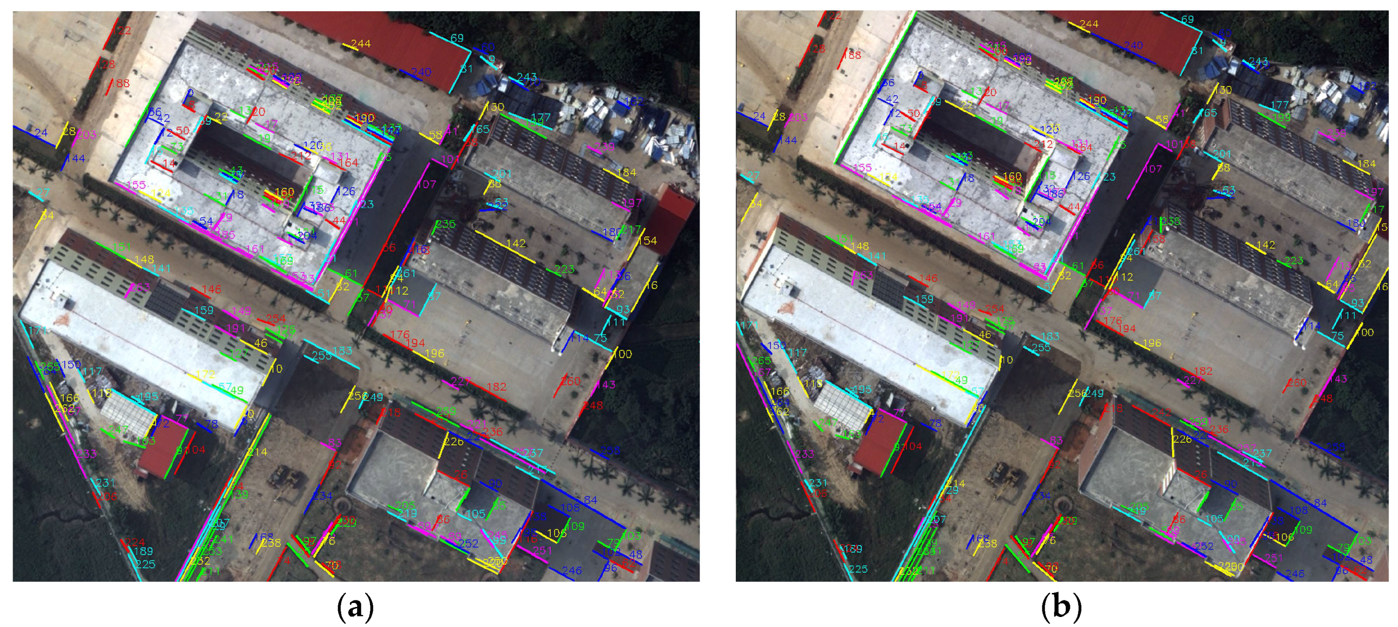
3.1. LJL Descriptor and Similarity Matching

LJL first uses the assumption of the two coplanar adjacent line segments to find the intersection point, after which the LJL structural unit is formed imitating the scale invariant feature transform (SIFT) descriptor and a gradient direction histogram in the local neighborhood of the structural unit is generated, thereby constructing an LJL descriptor. The LJL descriptor takes the juncture at the center and draws two circles with a radius of r and 2r pixels (r = 10 in this paper). These concentric circles are divided into four regions by two line segments. Each zone contains a sector and a ring, and the ring is divided into three sub-regions. In this way, a LJL structure has a total of 16 sub-regions and gradient orientation histograms with 8 main directions established in each sub-region. So, a 128-dimensional LJL descriptor vector is constructed, as shown in Figure 5.
As shown in Figure 5, two line segments L 1 ( 1 ) , L 2 ( 1 ) and juncture J ( 1 ) in the left image constructs a descriptor L 1 ( 1 ) J ( 1 ) L 2 ( 1 ) . The two line segments L 1 ( 2 ) , L 2 ( 2 ) and juncture J ( 2 ) in the right image construct another descriptor L 1 ( 2 ) J ( 2 ) L 2 ( 2 ) . Using L 1 ( 1 ) J ( 1 ) L 2 ( 1 ) as reference, L 1 ( 2 ) J ( 2 ) L 2 ( 2 ) attempts to match it.
Before two descriptor vectors to be compared, LJL firstly uses the crossing angles to discard many false candidates in advance. Suppose θ 1 and θ 2 are the crossing angle of two line segments of the two LJLs, respectively, the absolute difference θ = | θ 1 θ 2 | which should be smaller than a threshold is used as the constraint to decide whether they are a correctly matched ( θ = 30 ° in this paper). Then, the distance between the descriptor vector on the right and on the left is compared. Now, supposing D i 1 and D j 2 are the i th and j th descriptor vector in the first image and second image, respectively, D i 1 D j 2 d v is the criteria to accept the two descriptor vectors as an LJL match; if less than a certain threshold ( d v = 0.5 in this paper), it is identified as a match. After all the LJLs are matched, the planar homograpy can be estimated from existing matches. Therefore, matching for the remaining individual line segments can be conducted with this planar homograpy.

3.2. Back-Projection of MatchedLine Segments

After the matched line segments on rectified images are obtained using the LJL matching method, they can be back-projected onto original images. Taking a line segment on the left rectified image as an example, it is assumed that ( x 1 , y 1 ) and ( x 2 , y 2 ) are two endpoints respectively, and then the line segment on the original image obtained by the back-projection is:
l : [ x i , y i ] = M S [ x i , y i ] , ( i = 1 , 2 )

4. Experiment and Analysis

This experiment uses four groups of aerial oblique image pairs with POS information as the research object. POS can indirectly provide the camera’s angle and line elements. The LJL line matching method is used to process each group of image pairs. In order to reduce the time cost, the construction of multi-resolution pyramid is not performed in this experiment. In order to demonstrate the effect of the LJL algorithm visually, and to facilitate comparison with the processing effects of wide-baseline oblique images, firstly, a pair of adjacent conventional short-baseline images are selected on one strip for processing, before performing line matching on oblique images as shown in Figure 6. The matching results are shown in Table 1.
The second column in Table 1 represents the number of extracted line segments from each of the two images. The third column represents the number of LJL structure descriptors constructed in these stereo images. There are three values in the fourth column. They indicate the number of correctly matched line segments, the total number of matched line segments, and the matching accuracy rate, respectively. The fifth column represents the processing time. It can be seen that the LJL algorithm has a very good effect on the processing of conventional small viewing-angle aerial images, and the accuracy rate can reach to more than 97%, which can be used as a reference for processing the following wide-baseline oblique images.
The experimental area shown in the first image pair used in the experiment is located in the northeastern part of China. The distribution of buildings in the survey area is relatively sparse, and the elevation difference is obvious. The second, third, and fourth image pairs are located in the same survey area in eastern China, where the buildings are densely distributed. Most of the buildings are relatively flat; however, certain areas contain obvious elevation differences. The shooting angles of the first image pair are down-looking and back-looking. The second, third, and fourth image pairs are respectively down-looking and back-looking, left-looking and forward-looking, and left-looking and right-looking. In order to better display the overall shapes and orientation of the images (before and after transformation), the images shown in the figures maintain their intrinsic aspect ratio with no rotations. Parameters of the four image pairs are listed in Table 2. The four pairs of original images are shown in Figure 7.
It can be seen that many buildings appear rectangular in the down-looking images and approximately trapezoidal in the side-looking images. The circular structure in the down-looking image becomes elliptical in the side-looking images. Perspective transformation matrices are constructed using interior and exterior orientation elements of each image, and the above original images are rectified as new images, as shown in Figure 8.
From the above rectified images, it can be seen that the geographic orientation of every two images in each rectified image pair is the same; that is to say, perspective projections unify the images into the geodetic coordinate system. As a whole, the effective contents of the original images changed into trapezoids in rectified images. Especially for several side-looking images, the perspective distortion effects are large and the trapezoidal effects are obvious. It can also be seen that scenes close to cameras are compressed. The effective contents of down-looking images are approximate parallelograms due to the small viewing angles. Paying attention to the local details, it is observed that the trapezoidal or parallelogram structure (represented by a red rectangle) in the original side-looking image (image pair 3 in Figure 7) becomes an approximate rectangle (Figure 9a) in the rectified image (image pair 3* in Figure 8), and the ellipse (represented by a red circle) becomes a nearly perfect circle (Figure 9b).
Next, the original and rectified images were processed using the LJL algorithm to obtain line matching results. We use several different colors to help distinguish whether one match is correct. The number of correct matches, the total matching, and the matching accuracy rates are displayed directly in Figure 10, Figure 11, Figure 12 and Figure 13, respectively.
Finally, line segments matched on rectified images are back-projected to the original images, as shown in Figure 14. It can be seen that the accuracy and effect of the back-projected line segments are very good.
For convenience of expression, the line matching method performed directly on the original images is called LJL, whereas the method on the rectified images proposed in this paper is called Perspective–LJL. Relevant parameters and line matching results are shown in Table 3.
For depicting of the difference between LJL and Perspective–LJL intuitively, the correct number, the total number, and the accuracy rate of matched line segments (Table 3 are shown in Figure 15).
While analyzing and summarizing the data in Table 3 and Figure 15, the following discoveries are made:
(1)
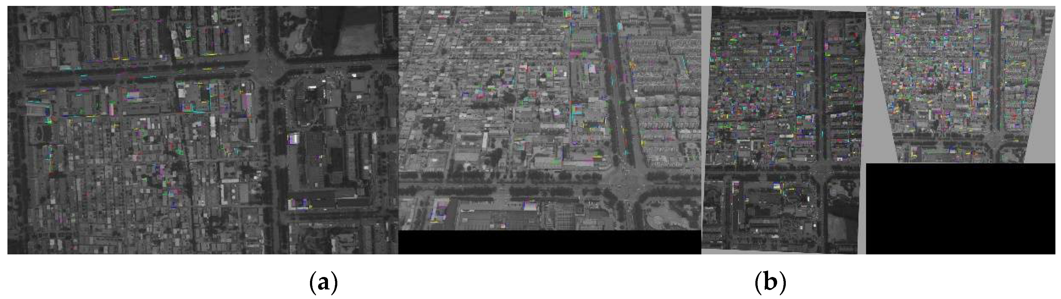
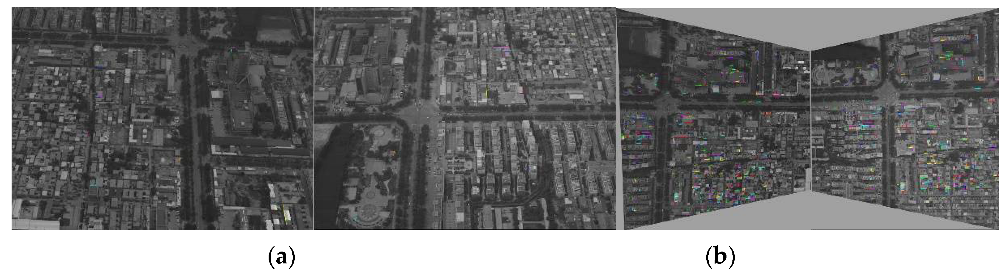
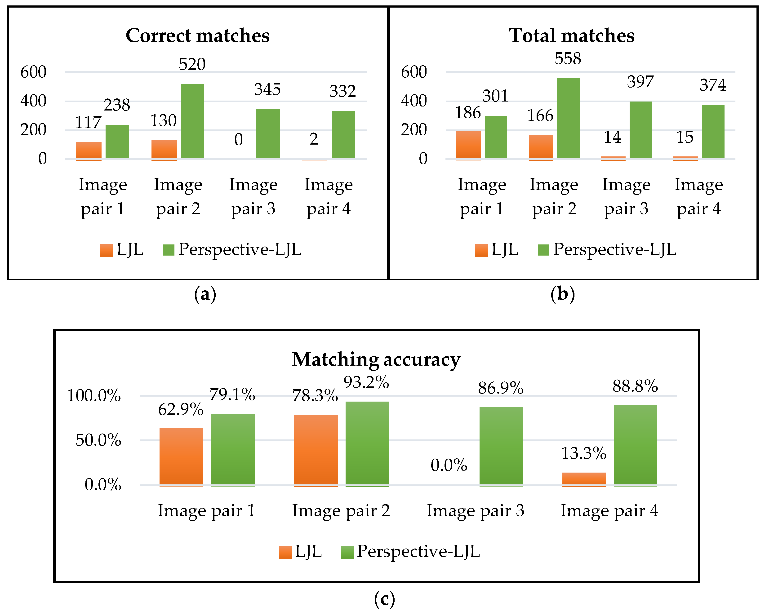
There is a large gap between the matching results of the four oblique image pairs with respect to the matching results of conventional images (Table 1). The matching accuracy rate is far less than 97%. There are thousands of lines extracted from the two pairs of down-looking and back-looking images; however, only a small proportion of lines are matched. The number of matched line segments is 186 and 166, whereas the accuracy rate is only 62.9% and 79.1%, respectively. Especially in the last two pairs of side-looking images, the baselines are wider and the difference in viewing angles is larger; therefore, the matched line segments are fewer in number, and the accuracy rate is 0% and 13.3%. The data fully reflects the matching difficulty of images with wide baselines and large viewing angles.
(2)
The number of line segments extracted from rectified images is less than that of original images. Because rectified images are resampled and their quality is lower than that of original images, the extraction effect will be worse. At the same time, their effective trapezoidal contents are smaller than the original images’ rectangular contents. For a line extraction algorithm such as LSD, the line segments smaller than a certain length threshold is not used (the threshold value in this algorithm is set to 20 pixels), so some line segments that are compressed to be shorter are discarded.
(3)
The number of LJL structures is directly proportional to the number of extracted line segments; that is, the more line segments are extracted, the more LJL structures can be constructed and the greater probability of matched line segments can be obtained. Although the number of line segments and the LJL structures of rectified images is smaller than that of the original images, the total number, correct number, and accuracy rate of the finally matched line segments is much higher. This is because although the original images have many LJL structures to try to match, due to serious distortions, the LJL structure descriptors to be matched are relatively different. This leads to large differences in descriptor vector distances, resulting in greater difficulty in matching and an increase in the mismatching rate.
(4)
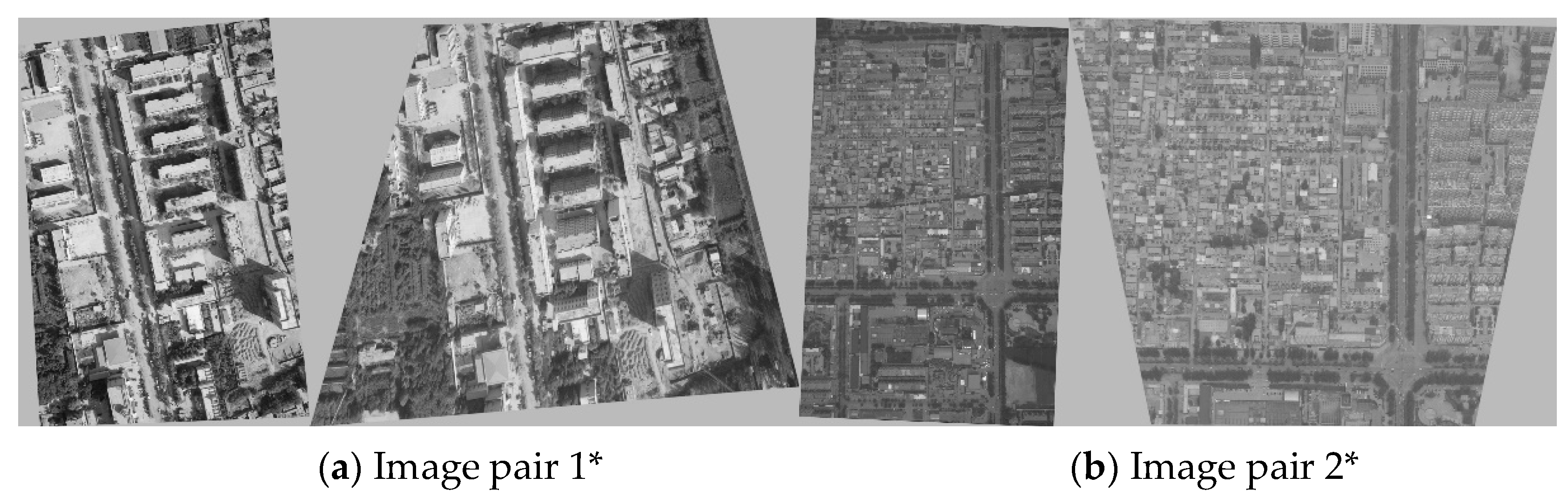
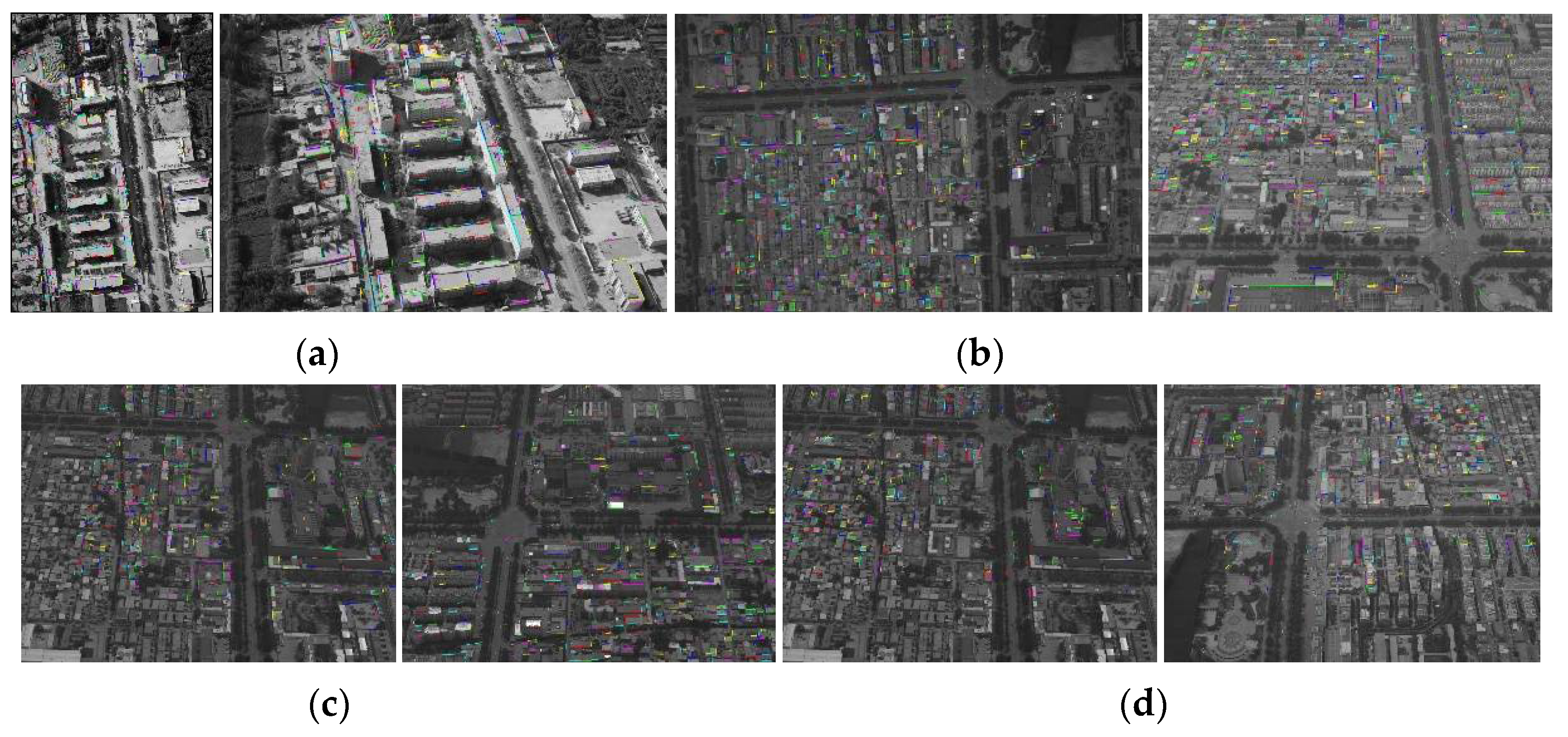
Comparing results of the first and second image pairs, it is found that both of these image pairs are down-looking and back-looking; however, for the first image pair, the correct matching rate is 62.9% under LJL processing, and 79.1% under Perspective–LJL; this is lower than the rate of 78.3% and 93.2% for the second image pair. Meanwhile, for the increase in the number of matched lines (both total number and the correct number), the effect of the second image pair is significantly better than that of the first image pair. In other words, the matching effect of the first image pair and the improving effect of Perspective–LJL on the first image pair is weaker than those observed in the second image pair. By observing the buildings’ distribution and topography in these two surveying areas, it can be seen that the elevation difference of buildings in the first image pair is large. There are many spatial planes with obvious differences, and occlusions are more serious. In the second image pair, most buildings are flatly distributed, and there are uniform deformations. It is appropriate to use a plane to fit the surfaces of these buildings, and the occlusions are not obvious. When the perspective transformation model is used to rectify buildings to a new spatial plane, the deformations can be well rectified.
(5)
Compared to the first and second image pairs, the Perspective–LJL method has more obvious effects on the extra-wide-baseline images of the third and fourth pairs, which fully prove the effectiveness of the proposed method.
(6)
By using the Perspective–LJL method, the matching accuracy rate is improved to 79.1%, 93.2%, 86.9%, and 88.8%, respectively; however, there still exists a gap of improving the matching rate up to 97% of the short-baseline images. This indicates that the perspective transformation model can only eliminate some of the perspective effects, and cannot completely solve the problems caused by large viewing angles.

5. Discussion

Four questions are discussed below. Firstly, on the basis of the comparison between the first and second image pairs, analyzing the impact of building distribution on line matching specifically from the second, third, and fourth rectified image pairs (the second, third, and fourth pairs of images are in the same area and are photographed at the same time). The second question addresses the time consumption of LJL and Perspective–LJL. The third discusses the matching outcomes affected by different POS accuracy. The fourth points out the applicability of Perspective–LJL to all existing line matching methods.

5.1. The Effect of Building Distribution on Line Matching

It is worth mentioning that internal flat areas were chosen (the quadrilateral areas formed by green lines and the image boundary) in the last three image pairs and the outer fluctuant areas with higher elevation difference (the remaining regions outside the quadrangles) as the studied objects. Mismatched line segments of these two different areas are counted from the matched images, as shown in Figure 16. First of all, it can be seen that the numbers of total matched segments in the outer areas are far less than those in the internal areas, but their incorrect rates are as follows. For image pair 2, the number of totally mismatched line segments is 38, and the mismatched number in the outer area is 25, occupying 65.8% of the total incorrect matches. For image pair 3, the total incorrect matches are 52, and incorrect matches in the outer area are 43, occupying 82.7%. For image pair 4, the total incorrect matches are 42, and incorrect matches in the outer area are 31, occupying 73.8%.
It can be seen that the incorrect rates are higher in the fluctuant area than those in the flat area, which is very low. This proves that the rectification effect is obvious for the flat area using the perspective projection model. This can greatly eliminate the distortion of the viewing angle on this flat projection surface, thus improving the line matching effect of the building edges. Although incorrect rates of the fluctuant regions on the rectified images are high, the matching effects are still improved relative to the original images. For these three image pairs, the number of correct matches in fluctuant regions is respectively increased from 21 to 90 in image pair 1, from 0 to 97 in image pair 2, and from 0 to 100 in the image pair 3, as shown in Figure 17.

5.2. Time Cost Analysis of the Proposed Method

The time consumption of the entire processing of the four groups of data is assembled in Table 4. The unit of measurement is seconds. It can be seen that the Perspective–LJL method does not significantly reduce the processing efficiency (as demonstrated by the first and second image pairs) by adding a resampling and back-projection process. It even takes less time than the LJL method (as demonstrated by the third and fourth image pairs).
In this section, the time complexity of the LJL algorithm is briefly analyzed. Since the left and right image processing is equivalent, it is assumed that the numbers of line segments extracted from the two images are both M . When constructing a LJL structure in the left image, it is necessary to select a reference line first, and then find a line that can form a LJL structure with the reference line from the remaining M − 1 lines. There are C M 2 combinations. Similarly, there are also C M 2 combinations for the right image. Then, the function that completes the matching is T ( M ) = C M 2 C M 2 . The time complexity is O ( M 4 ) . Due to reduction in the number of line segments on the rectified images, that is, a reduction of M , the line matching by Perspective–LJL takes less time. Although Perspective–LJL takes extra resampling and back-projection stages, linear time consumption is used. Resampling is a linear, pixel-by-pixel transformation through an inverse projection matrix. The back-projection of a line segment is a linear transformation of two endpoints with a projection matrix. Their time consumption is very small; therefore, the overall time costs of processing are better than those of the LJL method.

5.3. Matching Outcomes Affected by Different POS Accuracy

The proposed method depends on the EO (exterior orientation) of the camera. The POS device adopted in this paper is AEROcontrol which is made by IGI Corp (Integrated Geospatial Innovations, Kreuztal, Germany). Its angle-measuring device IMU (Inertial Measurement Unit) is of high accuracy. Angle-measuring precision is 0.005 degree at pitch and roll direction, separately, and 0.008 degree in yaw direction. However, this device is also expensive. In many applications, ordinary POS is more common, and the platform is more unstable on UAVs (Unmanned Aerial Vehicles). So, it is important to find out how many errors of rotations can be accepted.
Image pairs 2 and 3 were taken as test objects. Because the IMU angles are the main factors which affect the POS accuracy, different grades of noise were added to the three rotation angles. To this end, 15 different noisy angles ranging from 0° to 20° were chosen. Figure 18a,b show the number of correct matches and the matching accuracy under different noisy angles, respectively. For a better comparison, the number of correct matches using the LJL method (Figure 18a), which is a constant value of 130, is shown. Similarly, the matching accuracy values of 78.3% are shown in Figure 18b.
From the above discussion, it can be seen that no obvious changes for matching outcomes occur with noisy angles varying from 0° to 2°. It presents a slight decrease, with noisy angles varying from 2° to 5° and 5° to 10°, whereas a drastic decrease happened during tuning up noisy angles beyond 10°. To avoid such uncertainties, it is a good choice to fix the threshold at 5°. That is, when the IMU on a platform can provide an angle-measuring precision higher than 5°, the proposed method can be adopted. Therefore, it is applicable for general UAV aerial photogrammetry.

5.4. Applicability of Perspective Transformation Model to Other Line Matching Methods

It has already been mentioned in the introduction that the current line matching methods mainly include similarity matching based on the photometric information of line segments’ neighborhoods and geometric feature constraints, or matching based on a single line or lines group. The LJL method used in this paper belongs to the photometric, information-based matching approach, but also belongs to the lines group-based approach. It is analyzed and experimentally proven that the photometric information of line segments’ neighborhoods is recovered in the rectified images after perspective projection, which is the main reason for the matching improvement. In fact, it is also effective for the method based on images’ geometric feature constraints. This is because the relative geometric relationships among the various image features are also more realistic, and any constraint condition will be more accurate once an image is rectified as an orthomorphic image. It is the same for matching with a single line or lines group. Therefore, this method is equivalent to improving the image quality from the data source, and will inevitably improve the effect of various types of line matching methods.

6. Conclusions

This paper proposes an improved method for the line matching of wide-baseline images based on viewpoint-invariance. Perspective transformation matrices are established using the exterior orientation elements provided by POS and the original images are rectified into conformal images. By processing images whose distortion effects of large viewing angles have been eliminated, the number and accuracy of the matched line segments can be improved with no loss in time consumption meanwhile. With the better line matching outcomes, more quantitative and more effective 3D structural line information of buildings can be acquainted in subsequent 3D city reconstruction, compared with current state-of-art methods which perform line matching directly on original images. This method can be extended to other close-range photogrammetry fields, as well as the matching of other geometric features, such as points, circles, curves, etc.
This method can be applied to normal UAV aerial photogrammetry. When the angle-measuring accuracy of POS is higher than 5°, this method is recommended in order to achieve better matching results. In some special circumstances, such as low-cost IMU configuration, sharply shacked UAV platform, or sharp turning on MAV (Manned Aerial Vehicle) platform, however, the rotation angles for cameras will deviate significantly. It can be used in several matched point or line features from images to perform the initial orientation of the camera [27,28] or subsequent aerial triangulation [29], which can also obtain the pose information of the camera accurately, to some extent.

Author Contributions

Q.W., H.Z., and X.C. conceived and designed the experiments; Q.W. and Z.Z. performed the experiments; S.U., S.S. and F.L. analyzed the data and compiled the discussion; Q.W. wrote the paper and reviewed by S.U. All authors reviewed and approved the final manuscript.

Acknowledgments

This research was partially supported by funding from the National Natural Science Foundation of China, No. 51474217, No. 41701533 and Key Research and Development Program of Guangxi, No. AA17204086. Authors would like to thank China TOPRS Technology Co., Ltd. and Xiongwu Xiao for providing the aerial images.

Conflicts of Interest

The authors declare no conflict of interest.

References

  1. Morel, J.M.; Yu, G. ASIFT: A New Framework for Fully Affine Invariant Image Comparison. Siam J. Imaging Sci. 2009, 2, 438–469. [Google Scholar] [CrossRef] [Green Version]
  2. Xiao, X.; Zhang, C. Robust and rapid matching of oblique UAV images of urban area. In Proceedings of the SPIE—The International Society for Optical Engineering, San Diego, CA, USA, 25–29 August 2013. [Google Scholar]
  3. Tuytelaars, T. Wide baseline stereo matching based on local, affinely invariant regions. In Proceedings of the 11th British Machine Vision Conference, Bristol, UK, 11–14 September 2000; pp. 412–425. [Google Scholar]
  4. Petsa, E.; Patias, P. Relative orientation of image triples using straight linear features. Int. Arch. Photogramm. Remote Sens. 1994, 30, 663–669. [Google Scholar]
  5. Wang, Q.; Yan, L.; Sun, Y.; Cui, X.; Mortimer, H.; Li, Y. True orthophoto generation using line segment matches. Photogramm. Rec. 2018. [CrossRef]
  6. Zhang, Z.; Faugeras, O. Building a 3D world model with a mobile robot: 3D line segment representation and integration. In Proceedings of the 10th IEE International Conference on Pattern Recognition, Atlantic City, NJ, USA, 16–21 June 1990; Volume 1, pp. 38–42. [Google Scholar]
  7. Zhang, L.; Zhu, L. 3D line segments reconstruction for building facades with line matching across multi-image with non-geometry constraint. Hsi-An Chiao Tung Ta Hsueh J. Xi'an Jiaotong Univ. 2014, 48, 15–19. [Google Scholar]
  8. Tanaka, S.; Nakagawa, M. The Triplet Measured by Aerial Camera Using Line Segments Line Matching-Based Relative Orientation Using Triplet Camera. Int. Arch. Photogramm. Remote Sens. Spat. Inf. Sci. 2015, 40, 217–222. [Google Scholar] [CrossRef]
  9. Ok, A.Ö.; Wegner, J.D.; Heipke, C.; Rottensteiner, F.; Soergel, U.; Toprak, V. In-Strip Matching and Recons-truction of Line Segments from UHR Aerial Image Triplets. In Photogrammetric Image Analysis; Springer: Berlin/Heidelberg, Germany, 2011; pp. 61–72. [Google Scholar]
  10. Bay, H.; Ferraris, V.; Van Gool, L. Wide-baseline stereo matching with line segments. In Proceedings of the 2005 IEEE Computer Society Conference on Computer Vision and Pattern Recognition (CVPR), San Diego, CA, USA, 20–25 June 2005; Volume 1, pp. 329–336. [Google Scholar]
  11. Shi, W.; Zhu, C. The line segment match method for extracting road network from high-resolution satellite images. IEEE Trans. Geosci. Remote Sens. 2002, 40, 511–514. [Google Scholar]
  12. Wang, Z.; Liu, H.; Wu, F. MSLD: A robust descriptor for line matching. Pattern Recognit. 2009, 42, 941–953. [Google Scholar] [CrossRef]
  13. López, J.; Santos, R.; Fdez-Vidal, X.R.; Pardo, X.M. Two-view line matching algorithm based on context and appearance in low-textured images. Pattern Recognit. 2015, 48, 2164–2184. [Google Scholar] [CrossRef]
  14. Fan, B.; Wu, F.; Hu, Z. Line matching leveraged by point correspondences. In Proceedings of the 2010 IEEE Conference on Computer Vision and Pattern Recognition (CVPR), San Diego, CA, USA, 13–18 June 2010; pp. 390–397. [Google Scholar]
  15. Jia, Q.; Gao, X.; Fan, X.; Luo, Z.; Li, H.; Chen, Z. Novel Coplanar Line-Points Invariants for Robust Line Matching Across Views. In European Conference on Computer Vision; Springer: Cham, Switzerland, 2016; pp. 599–611. [Google Scholar]
  16. Lourakis, M.I.A.; Halkidis, S.T.; Orphanoudakis, S.C. Matching disparate views of planar surfaces using projective invariants. Image Vis. Comput. 2000, 18, 673–683. [Google Scholar] [CrossRef] [Green Version]
  17. Zhang, L.; Koch, R. An efficient and robust line segment matching approach based on LBD descriptor and pairwise geometric consistency. J. Vis. Commun. Image Represent. 2013, 24, 794–805. [Google Scholar] [CrossRef]
  18. Baillard, C.; Schmid, C.; Zisserman, A.; Fitzgibbon, A. Automatic line matching and 3D reconstruction of buildings from multiple views. In Proceedings of the ISPRS Conference on Automatic Extraction of GIS Objects from Digital Imagery, Munich, Germany, 8–10 September 1999; Volume 32, pp. 69–80. [Google Scholar]
  19. Wang, L.; Neumann, U.; You, S. Wide-baseline image matching using Line Signatures. In Proceedings of the 2009 12th IEEE International Conference on Computer Vision, Kyoto, Japan, 29 September–2 October 2009; pp. 1311–1318. [Google Scholar]
  20. Meltzer, J.; Soatto, S. Edge descriptors for robust wide-baseline correspondence. In Proceedings of the 2008 IEEE Conference on Computer Vision and Pattern Recognition, CVPR, Anchorage, AK, USA, 23–28 June 2008; pp. 1–8. [Google Scholar]
  21. Li, K.; Yao, J.; Lu, X. Robust line matching based on ray-point-ray structure descriptor. In Asian Conference on Computer Vision; Springer: Cham, Switzerland, 2014; pp. 554–569. [Google Scholar]
  22. Li, K.; Yao, J.; Lu, X.; Zhang, Z.; Zhang, Z. Hierarchical line matching based on line-junction-line structure descriptor and local homography estimation. Neurocomputing 2016, 184, 207–220. [Google Scholar] [CrossRef]
  23. Sun, Y.; Zhao, L.; Huang, S.; Yan, L.; Dissanayake, G. Line matching based on planar homography for stereo aerial images. ISPRS J. Photogramm. Remote Sens. 2015, 104, 1–17. [Google Scholar] [CrossRef] [Green Version]
  24. Gao, Y.; Liu, S.; Sun, Y.; Fan, S.; Tan, X. Line matching using a disparity map in rectified image space for stereo aerial images. Remote Sens. Lett. 2016, 7, 751–760. [Google Scholar] [CrossRef]
  25. Hartley, R.; Zisserman, A. Multiple View Geometry in Computer Vision; Cambridge University Press: Cambridge, UK, 2003. [Google Scholar]
  26. Gioi, R.G.V.; Jakubowicz, J.; Morel, J.M.; Randall, G. LSD: A line segment detector. Image Process. Line 2012, 2, 35–55. [Google Scholar] [CrossRef]
  27. Petsa, E.; Κarras, G. Constrained line-photogrammetric 3D reconstruction from stereopairs. Int. Arch. Photogramm. Remote Sens. 2000, 33, 604–610. [Google Scholar]
  28. Van den Heuvel, F.A. Line-photogrammetric mathematical model for the reconstruction of polyhedral objects. In Videometrics VI; El-Hakim, S.F., Ed.; SPIE: Bellingham, WA, USA, 1999; Volume 3174, pp. 60–71. [Google Scholar]
  29. Gerke, M. Using horizontal and vertical building structure to constrain indirect sensor orientation. ISPRS J. Photogramm. Remote Sens. 2011, 66, 307–316. [Google Scholar] [CrossRef]
Figure 1. Under ideal circumstances, the imaging situations achieved by stereo cameras of different viewing-angles on a rectangular building structure are as follows: (a) the imaging performance of two down-looking cameras; (b) the imaging performance of a down-looking camera and a side-looking camera; (c) the imaging performance of two side-looking cameras. The red line represents the edge of the building and the line segment to be matched.
Applsci 08 00938 g001
Figure 2. Five-lens oblique camera structure.
Applsci 08 00938 g002
Figure 3. Perspective distortion and rectification of the rectangular buildings: (a) the regular rectangle taken by down-looking camera; (b) the deformation under a back-looking camera; (c) the rectified rectangle of the deformed image.
Applsci 08 00938 g003
Figure 4. Line matching process using the line-juncture-line (LJL) method.
Applsci 08 00938 g004
Figure 5. LJL descriptor construction and matching. Two red line segments intersect at red dot as a LJL structure, and two black circles define the sub-regions together with green lines. The blue arrows (8 arrows in one cluster) represent the descriptor in each sub-region.
Applsci 08 00938 g005
Figure 6. The line matching effect of the LJL method on a conventional down-looking image pair. (a) First image; (b) Second image.
Applsci 08 00938 g006
Figure 7. Four pairs of original images. (a) Image pair 1; (b) Image pair 2; (c) Image pair 3; (d) Image pair 4. The red rectangle indicates a rectanglar building and the red circle indicates a round object, respectively, on the original images. The quadrilateral areas formed by green lines and the image boundary are flat areas and outer areas are fluctuant areas.
Applsci 08 00938 g007
Figure 8. Rectified images with perspective projection transformation. (a) Image pair 1*; (b) Image pair 2*; (c) Image pair 3*; (d) Image pair 4*. The red rectangle indicates a rectanglar building and the red circle indicates a round object, respectively, on the rectified images.
Applsci 08 00938 g008aApplsci 08 00938 g008b
Figure 9. Partial perspective rectification: (a) a trapezoid becomes a rectangle after rectification; (b) an ellipse becomes a circle after rectification.
Applsci 08 00938 g009
Figure 10. Comparison of the line matching results of the first image pair between original images and rectified images: (a) original images, 117/186/62.9%; (b) rectified images, 238/301/79.1%.
Applsci 08 00938 g010
Figure 11. Comparison of the line matching results of the second image pair between original images and rectified images: (a) original images, 130/166/78.3%; (b) rectified images, 520/558/93.2%.
Applsci 08 00938 g011
Figure 12. Comparison of the line matching results of the third image pair between original images and rectified images: (a) original images, 0/14/0%; (b) rectified images, 345/397/86.9%.
Applsci 08 00938 g012
Figure 13. Comparison of the line matching results of the fourth image pair between original images and rectified images: (a) original images, 2/15/15%; (b) rectified images, 332/374/88.8%.
Applsci 08 00938 g013
Figure 14. The matched line segments after back-projection to the original images. (a) The matched result on the original image pair 1; (b) The matched result on the original image pair 2; (c) The matched result on the original image pair 3; (d) The matched result on the original image pair 4.
Applsci 08 00938 g014
Figure 15. Comparison of the correct number, the total number, and the accuracy rate of the matched line segments for four image pairs. (a) the number of correct matched line segments; (b) the number of total matched line segments; (c) the accuracy of line matching.
Applsci 08 00938 g015
Figure 16. Comparison of the number of mismatched line segments between two different areas.
Applsci 08 00938 g016
Figure 17. Comparison of the number of correctly matched line segments in fluctuant areas.
Applsci 08 00938 g017
Figure 18. Matching outcomes with different angles of noise: (a) The number of correct matches; (b) Matching accuracy.
Applsci 08 00938 g018aApplsci 08 00938 g018b
Table 1. Line matching results of a conventional image pair.
Conventional ImagesExtracted Line SegmentsLine-Juncture-Line (LJL) StructuresMatched Line SegmentsTime (s)
Image pair465,499375,366258/266/97.0%4.3
Table 2. Parameters of the four groups of data.
DataResolutionPixel Size (um)Focal Length (mm)
Image pair 1Down-looking1326 × 19884.5235.0
Back-looking1988 × 13264.5250.0
Image pair 2Down-looking2817 × 17956.847.2
Back -looking2184 × 16206.880.2
Image pair 3Left-looking2622 × 19446.880.1
Forward-looking 2571 × 19166.880.1
Image pair 4Left-looking2622 × 19446.880.1
Right-looking2613 × 19336.880.1
Table 3. The comparison of line matching amongst the four pairs of original and rectified images.
DataMethodExtracted Line SegmentsConstructed LJL StructuresMatched Line Segments
(Correct/Total/Accuracy)
Image pair 1LJL1459,14591323,1251117/186/62.9%
Perspective–LJL1369,13691274,1121238/301/79.1%
Image pair 2LJL2795,23102800,1912130/166/78.3%
Perspective–LJL2640,21432636,2025520/558/93.2%
Image pair 3LJL2825,25703221,20460/14/0%
Perspective–LJL2461,21382877,1760345/397/86.9%
Image pair 4LJL2825,28793221,31962/15/13.3%
Perspective–LJL2461,27792877,3038332/374/88.8%
Table 4. Comparison of processing time consumption of the two methods.
Time Cost (s)Image Pair 1Image Pair 2Image Pair 3Image Pair 4
LJL12.318.020.524.8
Perspective–LJL12.419.519.824.6

