A Study on the Improvement Effect and Field Applicability of the Deep Soft Ground by Ground Heating Method

Abstract
:1. Introduction
2. Ground Heating Method Using Fossil Fuels
2.1. Introduction
2.2. Problems in Practical Use
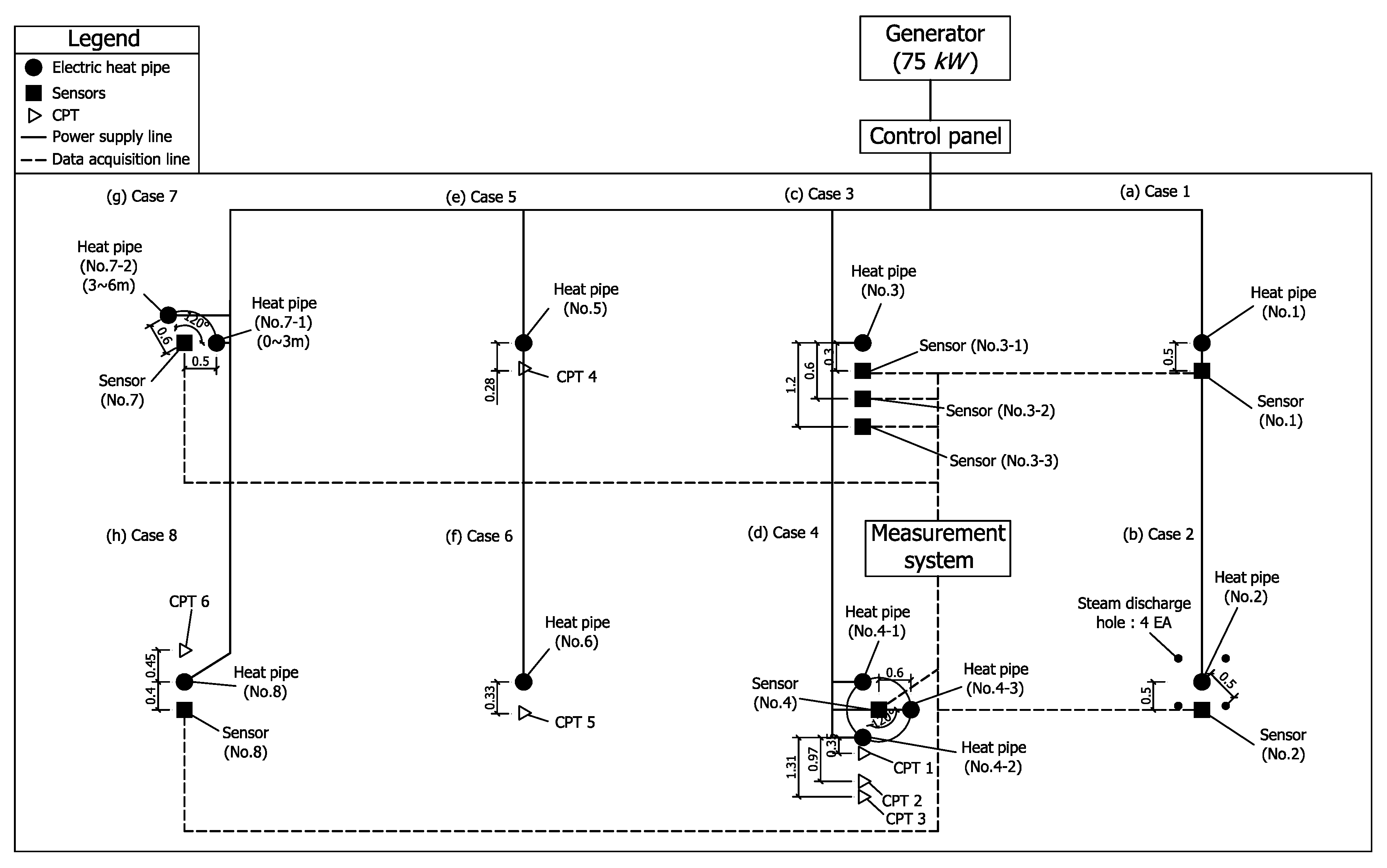
3. Field Ground Heating Experiment
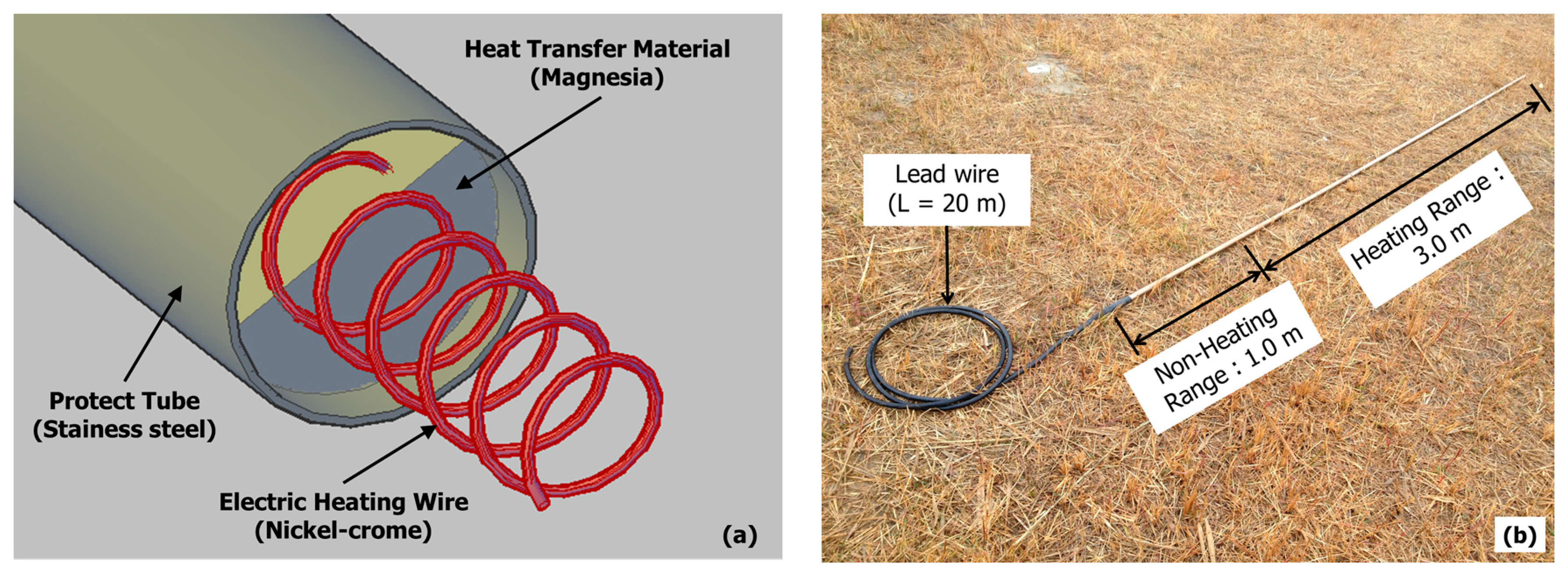
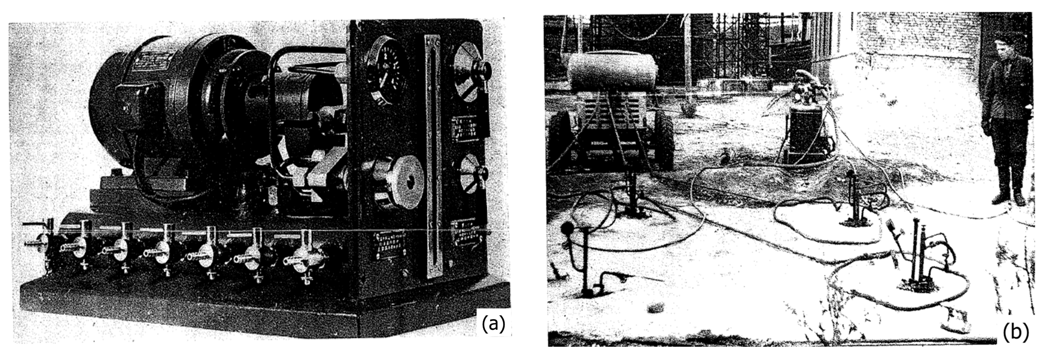
3.1. An Electric Heat Pipe for the Experiment
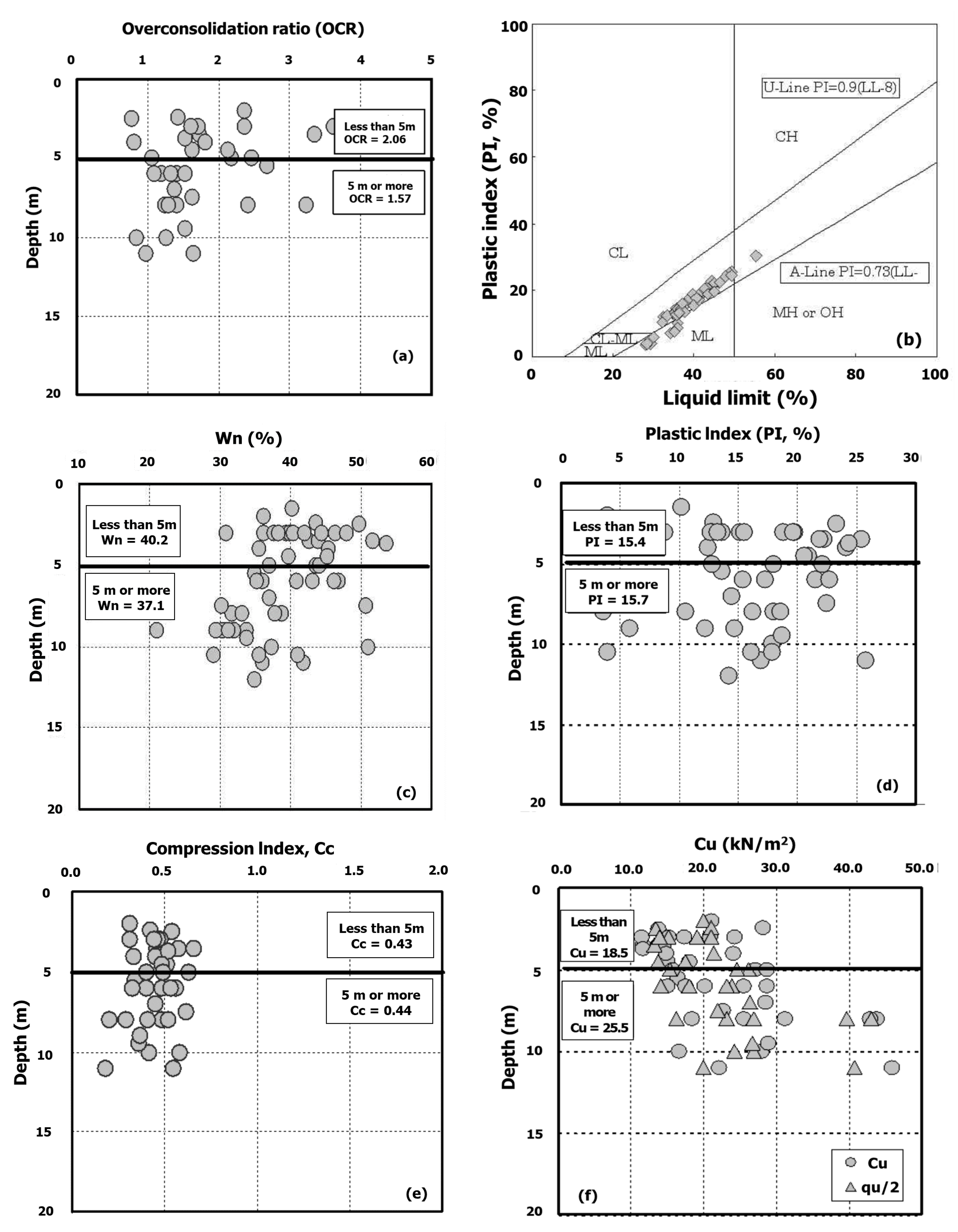
3.2. Experimental Site and Ground Condition
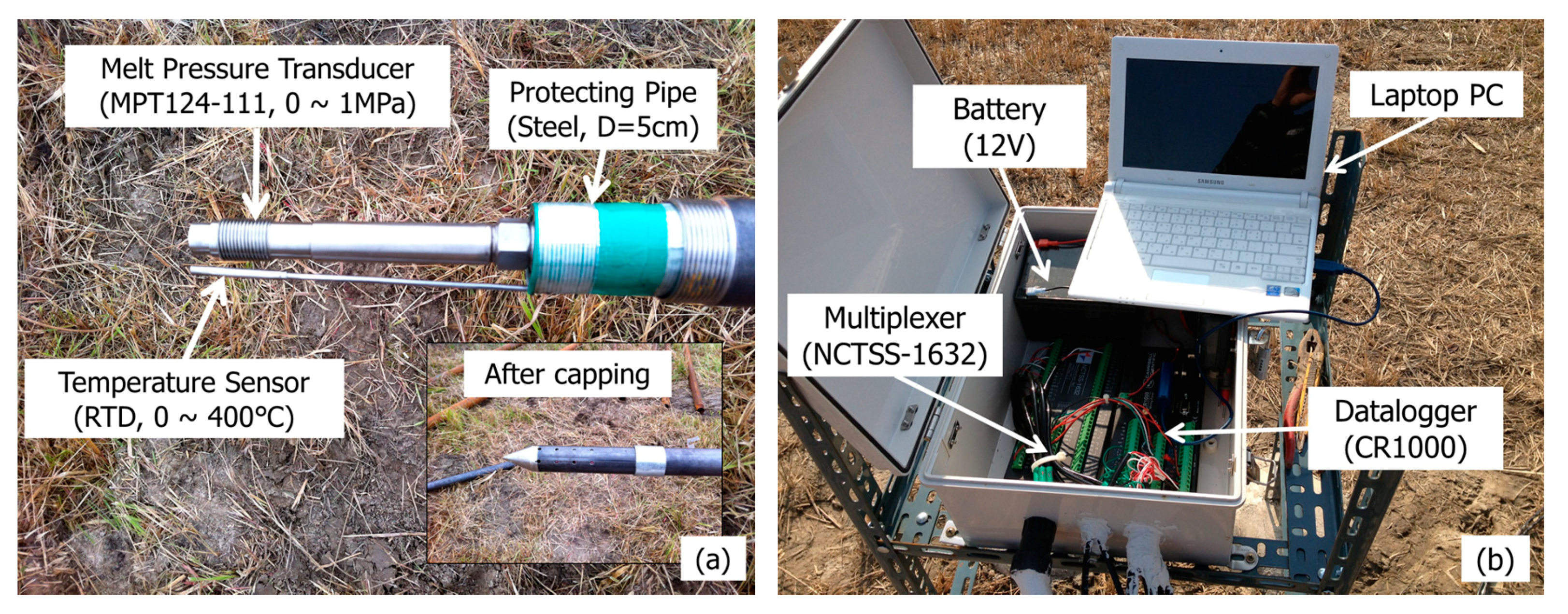
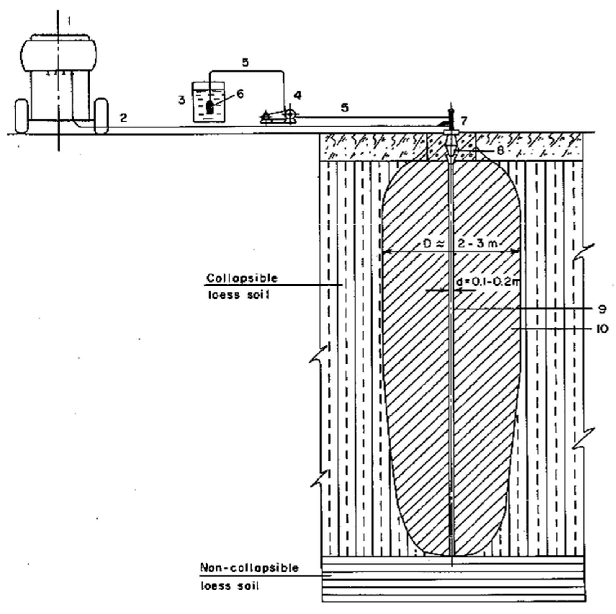
3.3. Installation of Experimental Equipment
3.4. Experiment Case
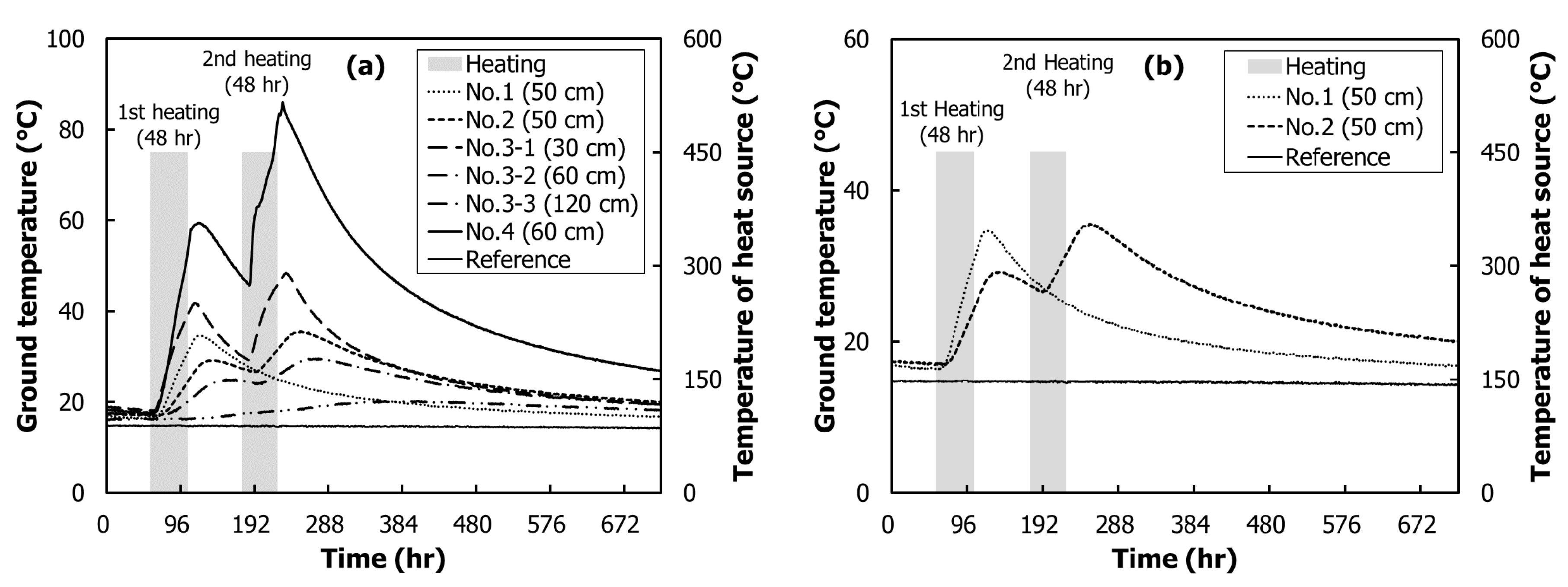
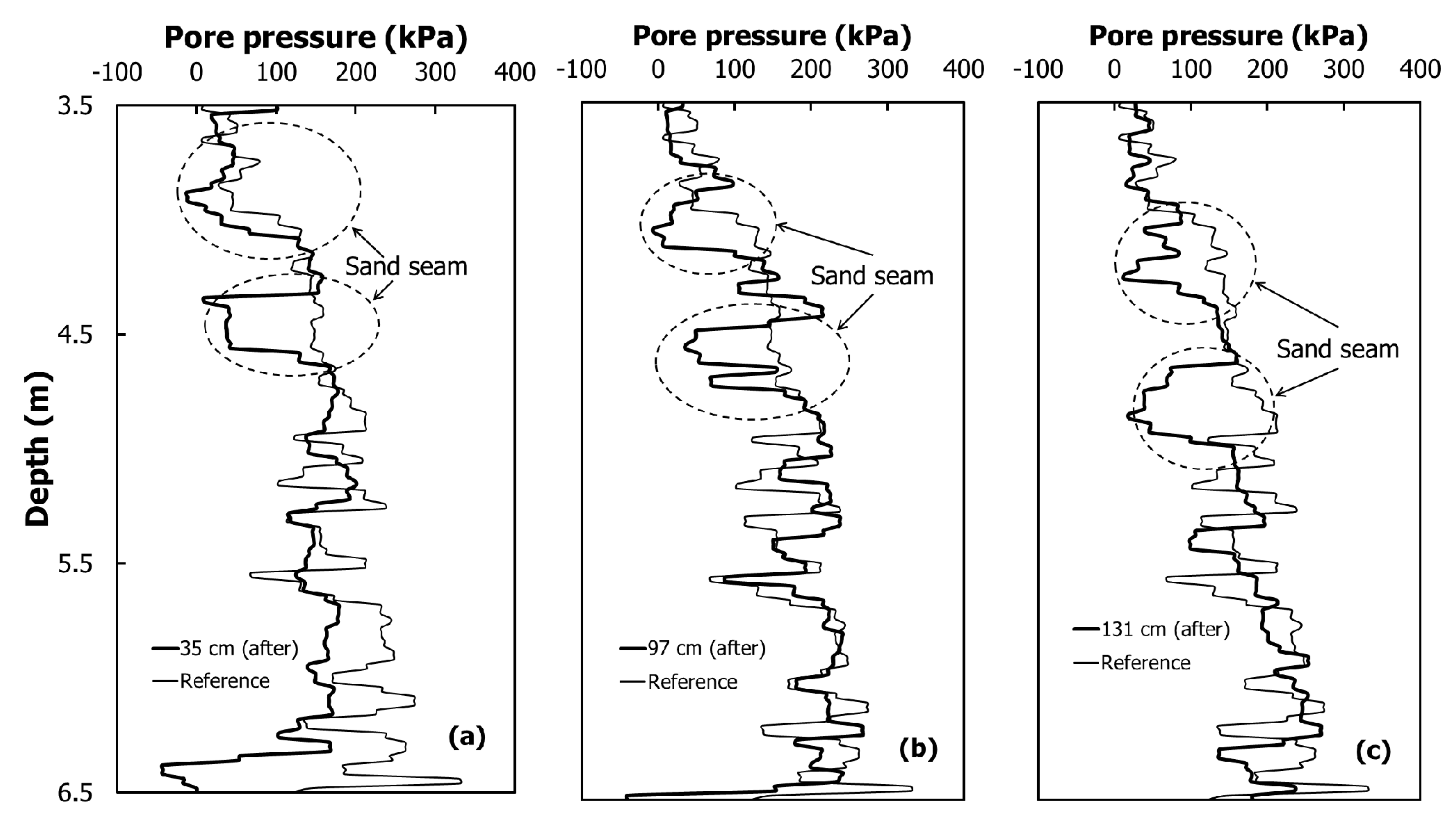
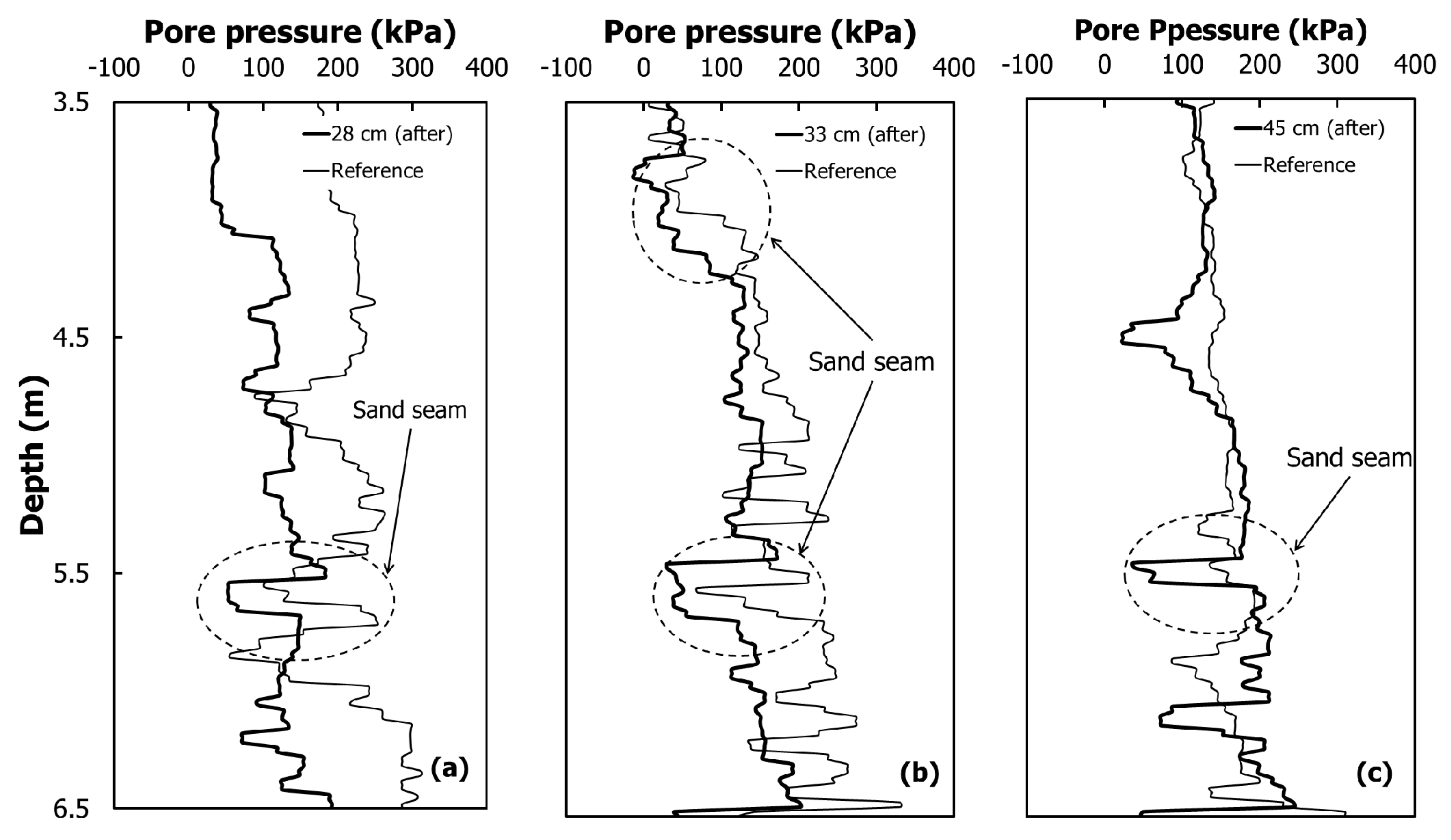
4. Results of Ground Heating Method
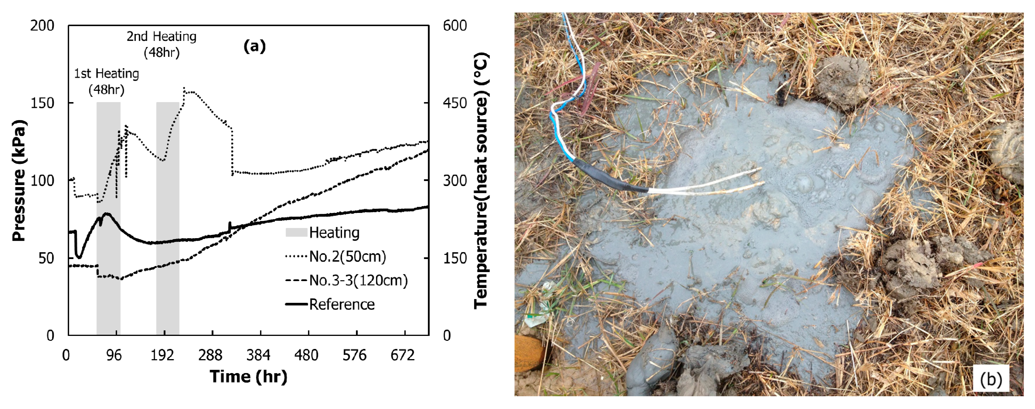
4.1. Heat Transfer Characteristic
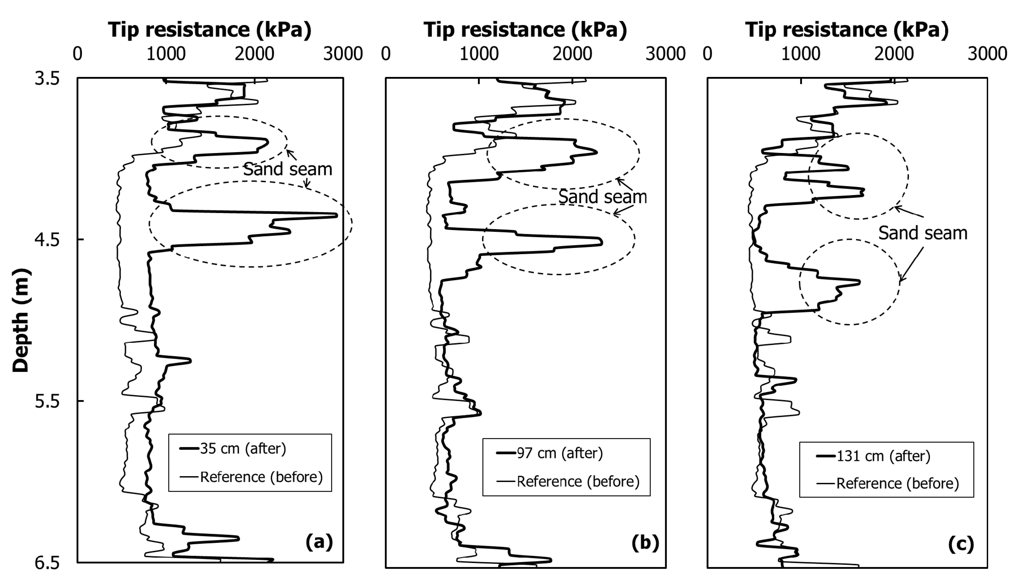
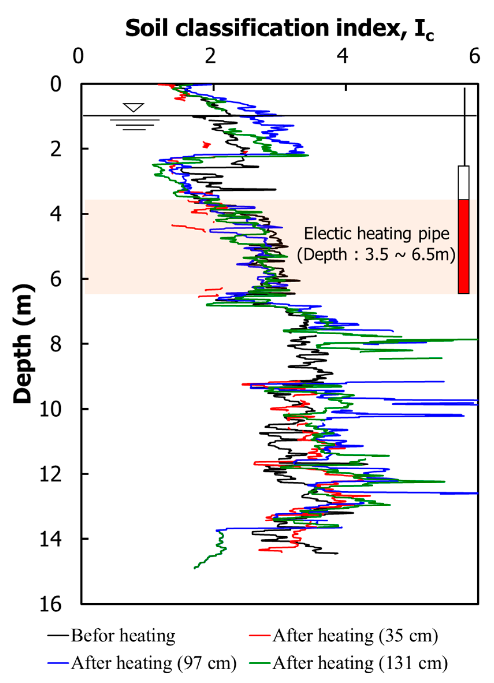
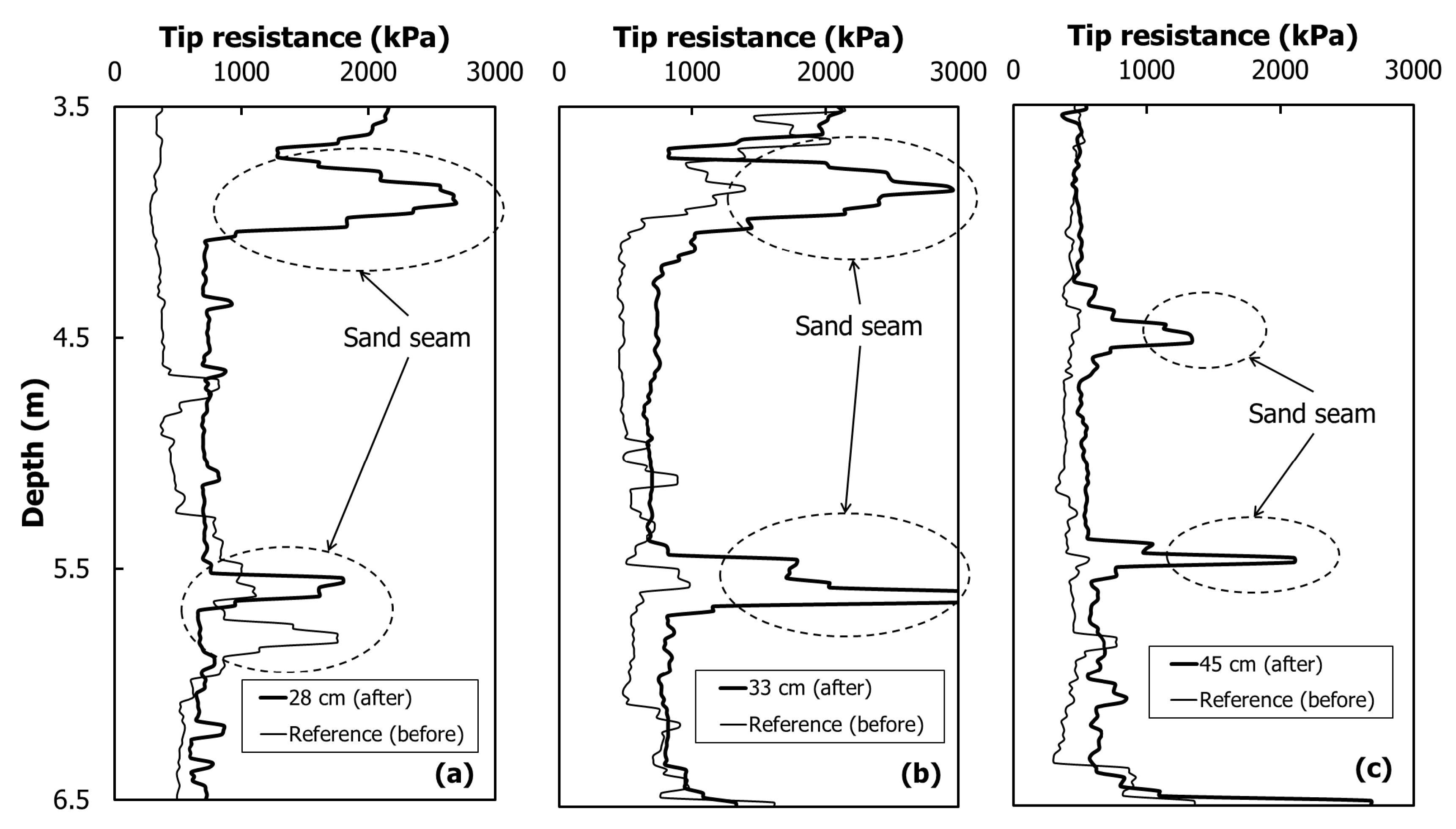
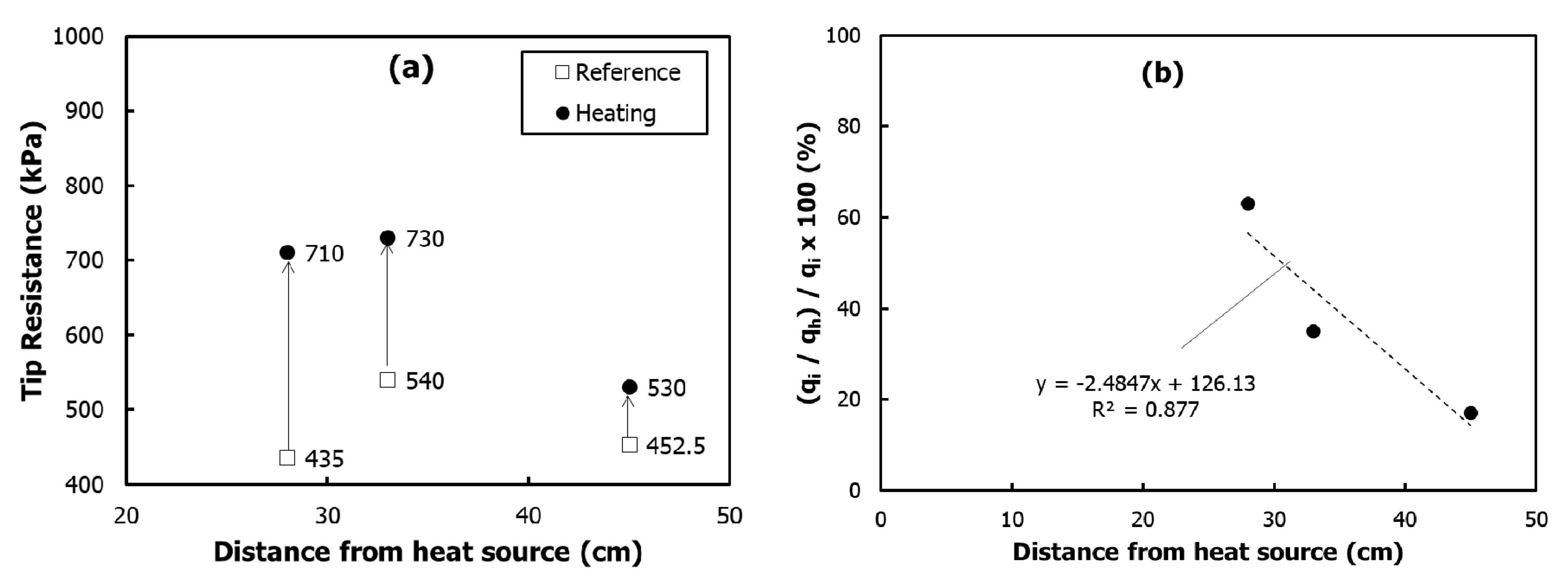
4.2. Soil Improvement Effect
5. Discussion
6. Conclusions
Conflicts of Interest
References
- Lambe, T.W. A Mechanistic Picture of Shear Strength in Clay; Research Conference on Shear Strength of Cohesive Soils; ASCE: Boulder, CO, USA, 1960; pp. 555–580. [Google Scholar]
- Park, M. A Study on Heat-Transfer Characteristics by a Ground-Heating Method. Sustainability 2018, 10, 412. [Google Scholar] [CrossRef]
- Das, B.M. Advanced Soil Mechanics; CRC Press: Boca Raton, FL, USA, 2013. [Google Scholar]
- Sakr, M.A.; Shahin, M.A.; Metwally, Y.M. Utilization of lime for stabilizing soft clay soil of high organic content. Geotech. Geol. Eng. 2009, 27, 105. [Google Scholar] [CrossRef]
- Bergado, D.; Alfaro, M.; Balasubramaniam, A. Improvement of soft Bangkok clay using vertical drains. Geotext. Geomembr. 1993, 12, 615–663. [Google Scholar] [CrossRef]
- Kirsch, F.; Kirsch, K. Ground Improvement by Deep Vibratory Methods; CRC Press: Boca Raton, FL, USA, 2014. [Google Scholar]
- Gaafer, M.; Bassioni, H.; Mostafa, T. Soil Improvement Techniques. Int. J. Sci. Eng. Res. 2015, 6, 217–222. [Google Scholar]
- Indraratna, B.; Rujikiatkamjorn, C.; Balasubramaniam, A.; McIntosh, G. Soft ground improvement via vertical drains and vacuum assisted preloading. Geotext. Geomembr. 2012, 30, 16–23. [Google Scholar] [CrossRef]
- Long, P.; Nguyen, L.; Bergado, D.; Balasubramaniam, A. Performance of PVD improved soft ground using vacuum consolidation methods with and without airtight membrane. Geotext. Geomembr. 2015, 43, 473–483. [Google Scholar] [CrossRef]
- Ye, G.-B.; Xu, Y.; Zhang, Z. Performance Evaluation of PVD-Reinforced Soft Soil with Surcharge and Vacuum Preloading. Int. J. Civ. Eng. 2018, 16, 421–433. [Google Scholar] [CrossRef]
- Rujikiatkamjorn, C.; Indraratna, B. Environmental Sustainability of soft soil improvement via vacuum and surcharge preloading. In Proceedings of the Geo-Congress 2014: Geo-characterization and Modeling for Sustainability, Atlanta, GA, USA, 23–26 February 2014; pp. 3658–3665. [Google Scholar]
- Lo, D.; Feng, T.; Ajlouni, M.; Mesri, G. Surcharging of soft ground to reduce secondary settlement. In Soft Soil Engineering; Routledge: Abingdon, UK, 2017; pp. 55–65. [Google Scholar]
- Bergado, D.; Chai, J.; Alfaro, M.; Balasubramaniam, A. Improvement Techniques of Soft Ground in Subsiding and Lowland Environment; A.A. Balkema Pubulishers: Brookfield, VT, USA, 1994. [Google Scholar]
- Indraratna, B.; Rujikiatkamjorn, C.; Nimbalkar, S.; Zhong, R.; McIntosh, G.W. Ground Improvement for Enhancing the Performance of Road, Rail, and Port Infrastructure; University of Wollongong: Wollongong, Australia, 2015. [Google Scholar]
- Kim, T.; You, S. Settlement analysis considering sand mat induced initial settlement in soft ground improved by PBD. Int. J. Civ. Eng. 2015, 13, 146–152. [Google Scholar]
- Han, J. Principles and Practice of Ground Improvement; John Wiley & Sons: Hoboken, NJ, USA, 2015. [Google Scholar]
- Park, M.; Im, E.; Shin, B.; Han, H. Improvement of shallow soil using electric heating equipment. J. Korean Geotech. Soc. 2012, 28, 41–54. [Google Scholar] [CrossRef]
- Kim, B.I.; Kim, D.H.; Kim, S.S.; Han, S.J. Consolidation characteristics of soft ground in suction drain method. J. Korean Soc. Civ. Eng. 2009, 29, 287–294. [Google Scholar]
- Park, M.; Lee, K.; Jang, J.; Han, H. Thermal Analysis of Silty Sand Soil by Pipe Heater Installed in the Ground. J. Korean Geoenviron. Soc. 2013, 14, 5–13. [Google Scholar]
- Kim, Y.-S.; Choo, J.-H.; Cho, Y.-S. Applicability Study on Deep Mixing for Urban Construction. J. Korea Acad. Ind. Cooper. Soc. 2011, 12, 500–506. [Google Scholar] [CrossRef]
- Beles, A.; Stănculescu, I. Thermal treatment as a means of improving the stability of earth masses. Geotechnique 1958, 8, 158–165. [Google Scholar] [CrossRef]
- Litvinov, I. Stabilization of Settling and Weak Clayey Soils by Thermal Treatment; Highway Research Board Special Report; Highway Research Board: Washington, DC, USA, 1960; pp. 94–112. [Google Scholar]
- Litvinov, I.; Rzhanitzin, B.; Bezruk, V. Stabilization of soil for Constructional Purposes. In Proceedings of the Fifth International Conference on Soil Mechanics and Foundation Engineering, Paris, France, 17–22 July 1961; pp. 775–777. [Google Scholar]
- Michot, A.; Smith, D.S.; Degot, S.; Gault, C. Thermal conductivity and specific heat of kaolinite: Evolution with thermal treatment. J. Eur. Ceram. Soc. 2008, 28, 2639–2644. [Google Scholar] [CrossRef]
- Wintermyer, A. Percentage of water freezable in soils. Public Roads 1925, 5, 5–8. [Google Scholar]
- Van der Lingen, G.; Biesenbach, J. Investigations on the heat treatment of subsoils and gravels. S. Afr. Ind. Chem. 1949, 3, 70–74. [Google Scholar]
- Bose, S. Stabilization of Certain Clayey Soils in India by Thermal Treatment; Indian Road Congress: New Delhi, India, 1953. [Google Scholar]
- Chandrasekharan, E.; Boominathan, S.; Sadayan, E.; Narayanaswamy, S.K. Influence of heat treatment on the pulverization and stabilzation characteristics of typical tropical soils. Highw. Res. Board Spec. Rep. 1969, 103, 161–172. [Google Scholar]
- Wang, M.; Benway, J.M.; Arayssi, A.M. The effect of heating on engineering properties of clays. In Physico-Chemical Aspects of Soil and Related Materials; ASTM International: West Conshohocken, PA, USA, 1990. [Google Scholar]
- Tang, A.-M.; Cui, Y.-J.; Barnel, N. Thermo-mechanical behaviour of a compacted swelling clay. arXiv, 2008; arXiv:0802.1433. [Google Scholar]
- Yilmaz, G. The effects of temperature on the characteristics of kaolinite and bentonite. Sci. Res. Essays 2011, 6, 1928–1939. [Google Scholar]
- Park, M.; Im, E.; Lee, K.; Han, H. Experimental Study for Consolidation by Electric Heating Systems. J. Korean Geoenviron. Soc. 2012, 13, 43–53. [Google Scholar]
- Kanthal, A.B. Heating Alloys for Electronic Household Appliances; Kanthal: Hallstahammar, Sweden, 2003. [Google Scholar]
- Park, K.-R. Engineering Properties of Sea Deposit Clay of West Coast in Korea Peninsula; Graduate School of Engineering, Konkuk University: Seoul, Korea, 2001. [Google Scholar]
- ASTM. Standard practice for rock core drilling and sampling of rock for site investigation. In ASTM D2113-99; ASTM International: West Conshohocken, PA, USA, 1999. [Google Scholar]
- Cosanti, B.; Squeglia, N.; Lo Presti, D. Evaluation of the degree of compaction of levees by a CPT-based method. In Proceedings of the 5th International Conference on Geotechnical Engineering for Disaster Mitigation and Rehabilitation, Taipei, Taiwan, 13–14 September 2017; Meei-Ling Lin: Taipei, Taiwan, 2017; pp. 193–206. [Google Scholar]
- Yang, H.; Russell, A.R. Cone penetration tests in unsaturated silty sands. Can. Geotech. J. 2015, 53, 431–444. [Google Scholar] [CrossRef]
- Lo Presti, D.; Stacul, S.; Meisina, C.; Bordoni, M.; Bittelli, M. Preliminary Validation of a Novel Method for the Assessment of Effective Stress State in Partially Saturated Soils by Cone Penetration Tests. Geosciences 2018, 8, 30. [Google Scholar] [CrossRef]
- Robertson, P. Soil classification using the cone penetration test. Can. Geotech. J. 1990, 27, 151–158. [Google Scholar] [CrossRef]


| Borehole No. | Marine Sediments (m) | WS (m) | WR (m) | SR (m) | |
|---|---|---|---|---|---|
| Clay | Sand | ||||
| BH-9 | 6.0 | - | 1.0 | - | 1.5 |
| BH-10 | 14.0 | 6.5 | - | - | 1.5 |
| BH-12 | 10.2 | 8.8 | 1.0 | 2.5 | - |
| SPT N | 0/30–5/30 | 3/30–50/20 | 50/28–50/14 | 50/5–50/4 | - |
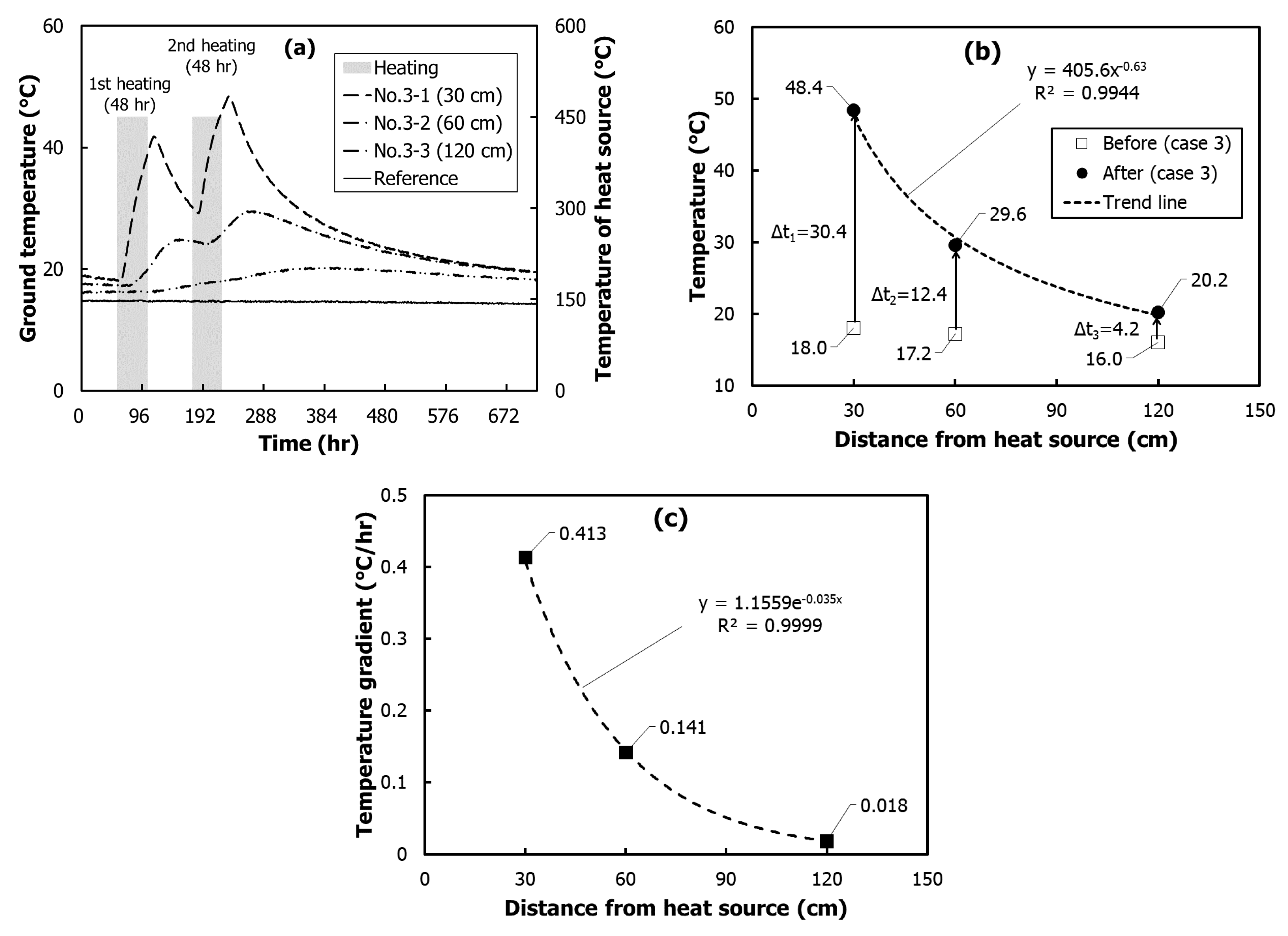
| Sensor | ||||
|---|---|---|---|---|
| 3-1 | 0.3 | 18.00 | 48.43 | 0.413 |
| 3-2 | 0.6 | 17.18 | 29.56 | 0.141 |
| 3-3 | 1.2 | 16.01 | 20.21 | 0.018 |
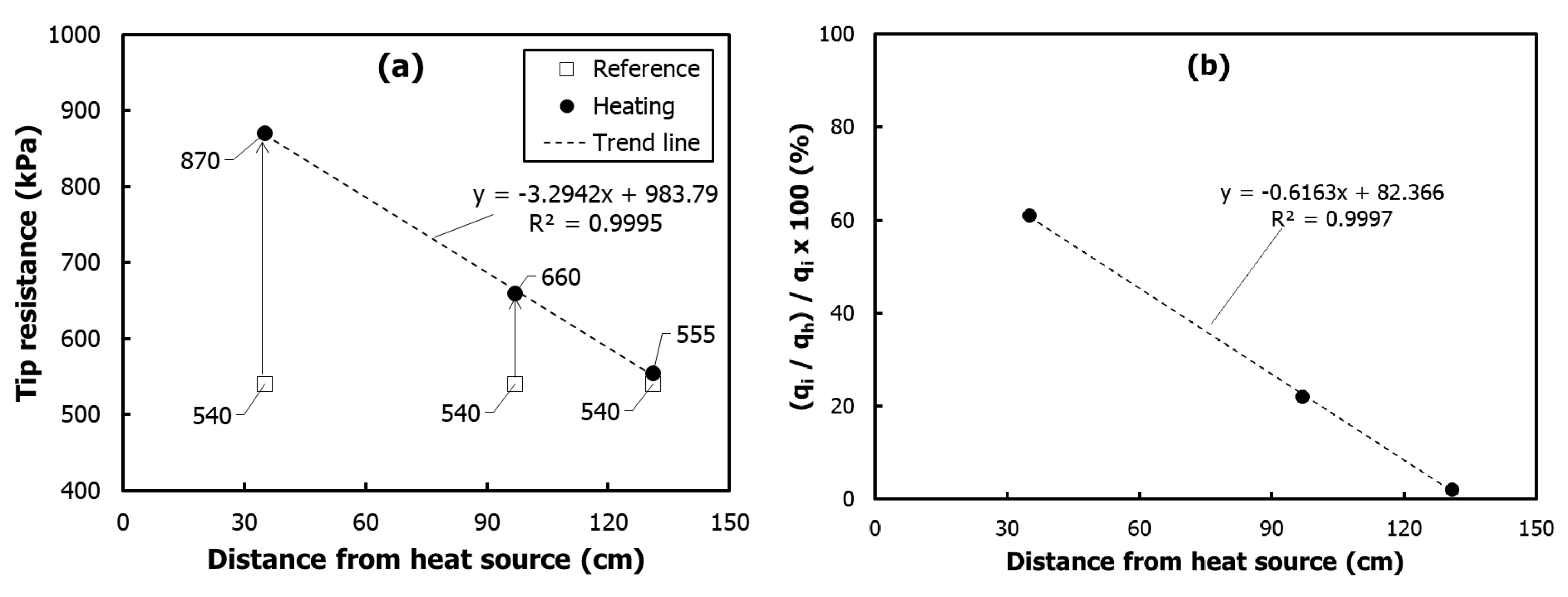
| Case | () | () | () | () |
|---|---|---|---|---|
| 4 | 0.35 | 540.0 | 870.0 | 61 |
| 0.97 | 540.0 | 660.0 | 22 | |
| 1.31 | 540.0 | 555.0 | 2 | |
| 5 | 0.28 | 435.0 | 710.0 | 63 |
| 6 | 0.33 | 540.0 | 730.0 | 35 |
| 8 | 0.45 | 452.5 | 530.0 | 17 |
© 2018 by the author. Licensee MDPI, Basel, Switzerland. This article is an open access article distributed under the terms and conditions of the Creative Commons Attribution (CC BY) license (http://creativecommons.org/licenses/by/4.0/).
Share and Cite
Park, M. A Study on the Improvement Effect and Field Applicability of the Deep Soft Ground by Ground Heating Method. Appl. Sci. 2018, 8, 852. https://doi.org/10.3390/app8060852
Park M. A Study on the Improvement Effect and Field Applicability of the Deep Soft Ground by Ground Heating Method. Applied Sciences. 2018; 8(6):852. https://doi.org/10.3390/app8060852
Chicago/Turabian StylePark, Mincheol. 2018. "A Study on the Improvement Effect and Field Applicability of the Deep Soft Ground by Ground Heating Method" Applied Sciences 8, no. 6: 852. https://doi.org/10.3390/app8060852
APA StylePark, M. (2018). A Study on the Improvement Effect and Field Applicability of the Deep Soft Ground by Ground Heating Method. Applied Sciences, 8(6), 852. https://doi.org/10.3390/app8060852