Article

Evaluation of Fe-Based Shape Memory Alloy (Fe-SMA) as Strengthening Material for Reinforced Concrete Structures

Department of Civil Engineering, Chungbuk National University, 1 Chungdae-ro, Seowon-Gu, Cheongju, Chungbuk 28644, Korea
*
Author to whom correspondence should be addressed.
Appl. Sci. 2018, 8(5), 730; https://doi.org/10.3390/app8050730
Submission received: 6 April 2018 / Revised: 30 April 2018 / Accepted: 3 May 2018 / Published: 5 May 2018
(This article belongs to the Special Issue Emerging Construction Materials and Sustainable Infrastructure)

Abstract

:
This paper aims to evaluate potential of an Fe-based shape memory alloy (Fe-SMA) for strengthening civil structures. Mechanical properties of the Fe-SMA were investigated with a direct tensile test, which showed the stress-induced transformation, stress at fracture of the Fe-SMA, and modulus of elasticity. Heating temperature ranging from 110 to 220 and pre-straining level ranging from 2% to 8% of the Fe-SMA were considered as variables to provoke a shape memory effect (SME), which generates a recovery stress. The recovery stresses ranged from 207.59 MPa to 438.61 MPa, which plays a role in introducing a pre-stressing force to concrete members. Bonding behavior of the Fe-SMA embedded into a groove with a cement-based mortar filler was investigated to determine the required bonding length to fully develop the pre-stressing force of the Fe-SMA with a near-surface mounted (NSM) strengthening technique. All the tested specimens showed slippage failure and suggested a minimum bonding length of 600 mm. The pre-stressing force applied on the concrete can be calculated with the recovery stress of the Fe-SMA. Based on those test results, the Fe-SMA shows sufficient potential to be used as strengthening material for civil structures.

1. Introduction

Shape memory alloys (SMAs) are unique and widely known materials that can return to a pre-defined shape when heated above a defined temperature. The pre-defined shape is memorized by changes in temperature or action of stresses. The SMAs were developed from the discovery of Au-Cd alloys with a shape memory effect (SME) by Chang and Read in 1951 [1]. As well as Ti-Ni SMAs publicized by Buehler in 1962 [2], various SMAs such as Cu-Zn-Al alloys, Mn-Cu alloys, and Cu-Al-Ni alloys have been discovered with a SME [3,4,5]. The SME from those SMAs is generated by a thermoelastic phase transformation. The thermoelastic phase transformation known as transformation hysteresis is a transformation behavior of the crystal structure that depends on a change in temperature. The SMAs have two phases: martensite, which is stable in low temperature; and austenite, which is stable in high temperature. The phase transformation occurs between the martensite and austenite phase by change in temperature. Forward phase transformation takes place during temperature change from low to high. On the contrary, the reverse phase happens during change of temperature from high to low [6,7,8,9]. Although the aforementioned SMAs with such phase transformation process have been used in such fields as aerospace and the medical industry, due to expensive cost of production and raw material it is not feasible for them to be used in civil structures which require large and stable recovery stresses for active control, damping, and pre-stressing strengthening material [9,10,11,12]. In 1982, Sato discovered a Fe-30Mn-1Si alloy and subsequently the SME from the Fn-Mn alloy, which contributed to lowering production cost [8]. In addition, as compared to the aforementioned SMAs, Fe-SMAs have wide transformation hysteresis and high stiffness and strength [11,12,13,14,15,16]. Initially discovered Fe-SMAs, including Fe-Pt, Fe-Pd, and Fe-Ni-Co, showed a transformation hysteresis which was caused by the transformation phase from the γ-austenite phase that is stable in high temperature to the ε-martensite phase that is stable in low temperature. However, not only did this transformation hysteresis narrow thermal hysteresis, but also the dissolution and homogenization processes were complicated and cyclic heating treatment known as “training” was required to improve the SME [5,13,14,17]. Those limitations and increased production cost made the Fe-SMAs challengeable in application in structures for civil engineering similar to Ni-Ti SMAs [9,10,18]. Later, Fe-SMAs processing a wide transformation hysteresis with different precipitates were discovered. In 2001, Kajiwara et al. and Farjami et al. discovered fine NbC and VN precipitates in the microstructure that enhanced the SME of Fe-SMAs without any training process [19,20]. Dong et al. and Leinenbach et al. improved the SME of Fe-17Mn-5Si-10Cr-4Ni-1(V,C) and Fe-16Mn-5Si-10Cr-4Ni-1(V,N) by mass fraction [21,22]. The developed SME, high stiffness, high strength, and low production cost of these Fe-SMAs prompted international research into its application in such civil engineering fields as damping, active control, and pre- or post-stressing tensioning of structures [11,14,23,24,25,26,27,28,29].
When the deformation of the Fe-SMA generated by the transformation hysteresis is constrained, the energy to be used for the transformation phase is used in recovery stress, which can be a pre-stressing strength in concrete structures. In 2004, Moser demonstrated feasibility of the pre-stressing strength in a cementitious mortar by using a short fiber type of Ni-Ti-based SMAs. Prism specimens were heated up to 180 °C, which induced the pre-stressing strength of 845 MPa to the surrounding mortar layers [30]. The pre-stressing strength ranging from 130 MPa to 580 MPa are reported at phase transformation temperature of 130 to 580 on different Fe-Mn-Si alloys, which showed that the Fe-SMAs could be used as the strengthening material for civil structures [6]. Czaderski et al. in 2014 reported that recovery stresses ranged from 250 MPa to 300 MPa when heating to 160 , which demonstrated the general feasibility of the Fe-SMA strips [10].
The aim of this paper is to evaluate the feasibility of the Fe-SMA as the strengthening material for civil structures based on thermal mechanical test results. The recovery stresses of the Fe-SMAs were investigated with five different recovery temperatures ranging from 100 to 220 and with four different pre-straining levels ranging from 2% to 8%. Additionally, a bonding test was performed to understand the bond behavior and to determine the minimum bonding length of the Fe-SMA. For this bonding test, the Fe-SMAs were embedded with a near-surface mounted (NSM) technique which involves the embedding of Fe-SMA into grooves opened on a concrete surface. Finally, a cement-based mortar bar including the Fe-SMA was tested to calculate a compressive force—namely a pre-stressing force transferred from the recovery stress of the Fe-SMA to the surrounding concrete. The pre-stressing force was calculated based on the recovery stress, the thermal mechanical properties of the strengthening material and the equivalent modulus of elasticity on the concrete. Based on those material test results, a flexural strengthening performance of a reinforced concrete (RC) beam with NSM Fe-SMA strip will be evaluated in further research.

2. Experimental Program

2.1. Fe-SMAs

Fe-SMA used for this paper were produced by re-fer AG Company in Switzerland. The Fe-SMA has a chemical composition of iron, manganese, silicon, chromium, and nickel, Fe-17Mn-5Si-10Cr-4Ni-1 (V,C) when categorized by mass ratio [21,22]. As a preliminary test for this paper, a direct tensile test was conducted to investigate the mechanical properties and material behavior on the Fe-SMA. As a result of the tests in Figure 1, the modulus of elasticity, limit of proportionality ( σ 0.01 ), 0.2% proof stress ( σ 0.2 ), and the stress at fracture of the Fe-SMA referred to as ultimate tensile strength ( σ U T S ) were taken as 133 GPa, 200 MPa, 463 MPa, and 863 MPa, respectively, which are lower than the 173 GPa, 230 MPa, 546 MPa, and 1015 MPa reported in [31].

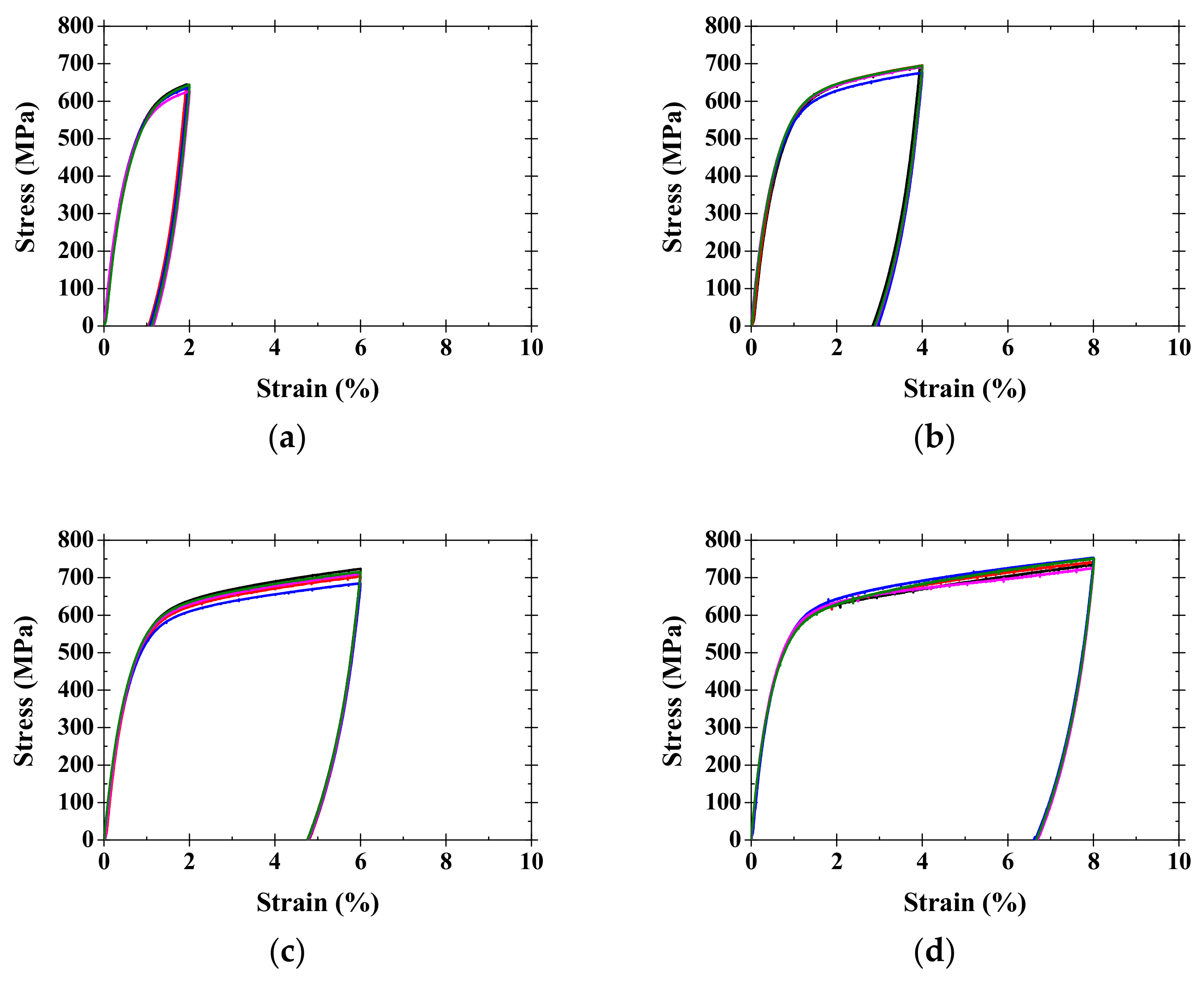
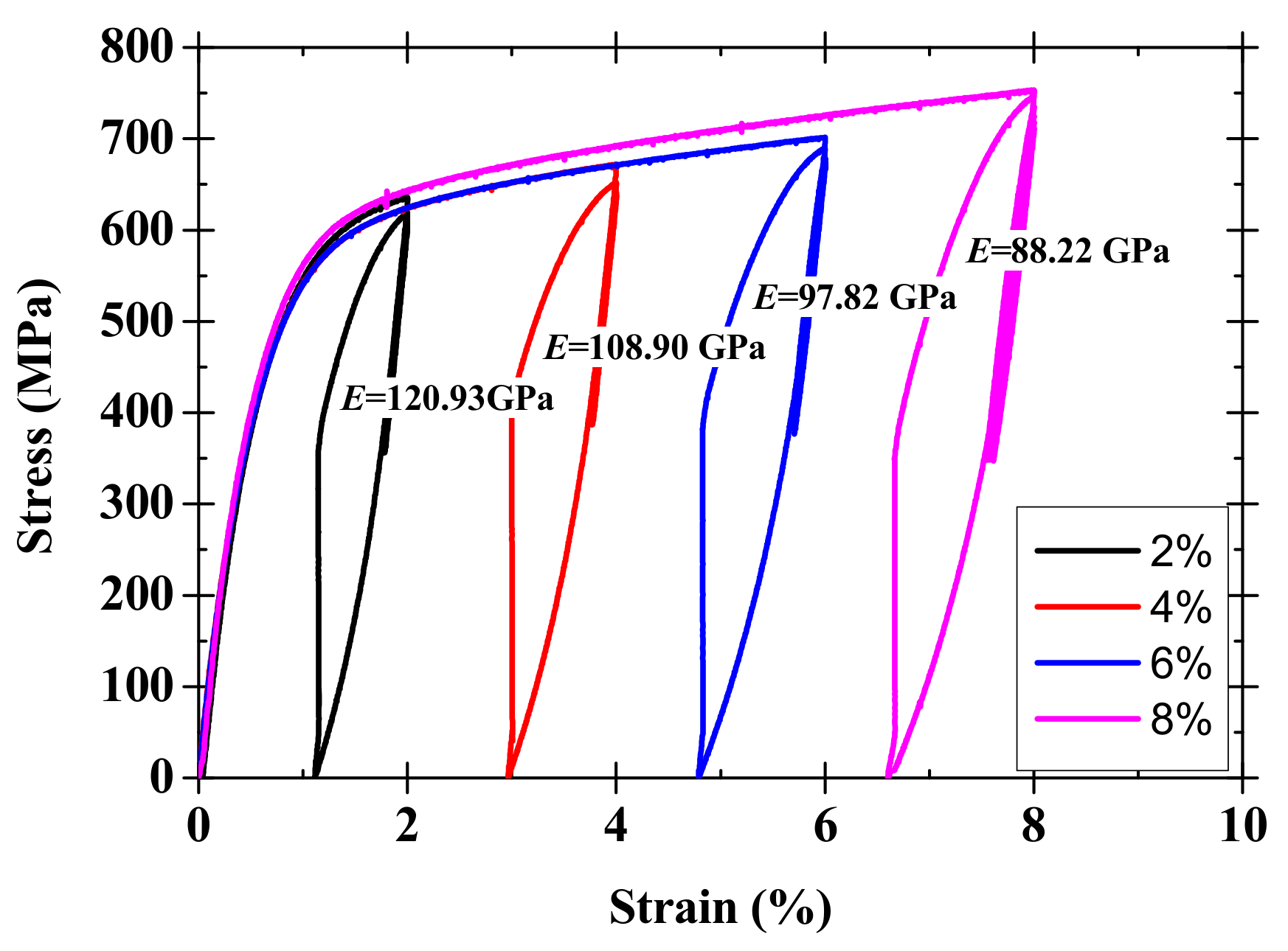
2.2. Pre-Straining of Fe-SMA

The Fe-SMA specimens for a pre-straining process and a recovery stress test had length, width, and thickness of 300 mm, 10 mm, and 1.5 mm, respectively. To prevent stress concentration by hydraulic wedge grips during the pre-straining process and recovery stress test, dumbbell shaped specimens with an arc transition were precut at both ends, as shown in Figure 2a. A total of 16 specimens were tensioned to four different pre-straining levels (2%, 4%, 6% and 8%) with a universal testing machine (UTM) of 100 kN loading capacity under the machine head at the rate of 0.25 mm/min. Four specimens were prepared for each pre-straining level to obtain reliable test data. After the specimen was fully extended up to the target strain level, the load was removed at the rate of 0.25 mm/min until the residual stress on the specimen reached zero, and then the residual strain was recorded. The tensile load was measured by a load cell equipped inside the UTM test machine and a tensile strain was measured by using the strain gauge attached at the mid-length of the specimen.

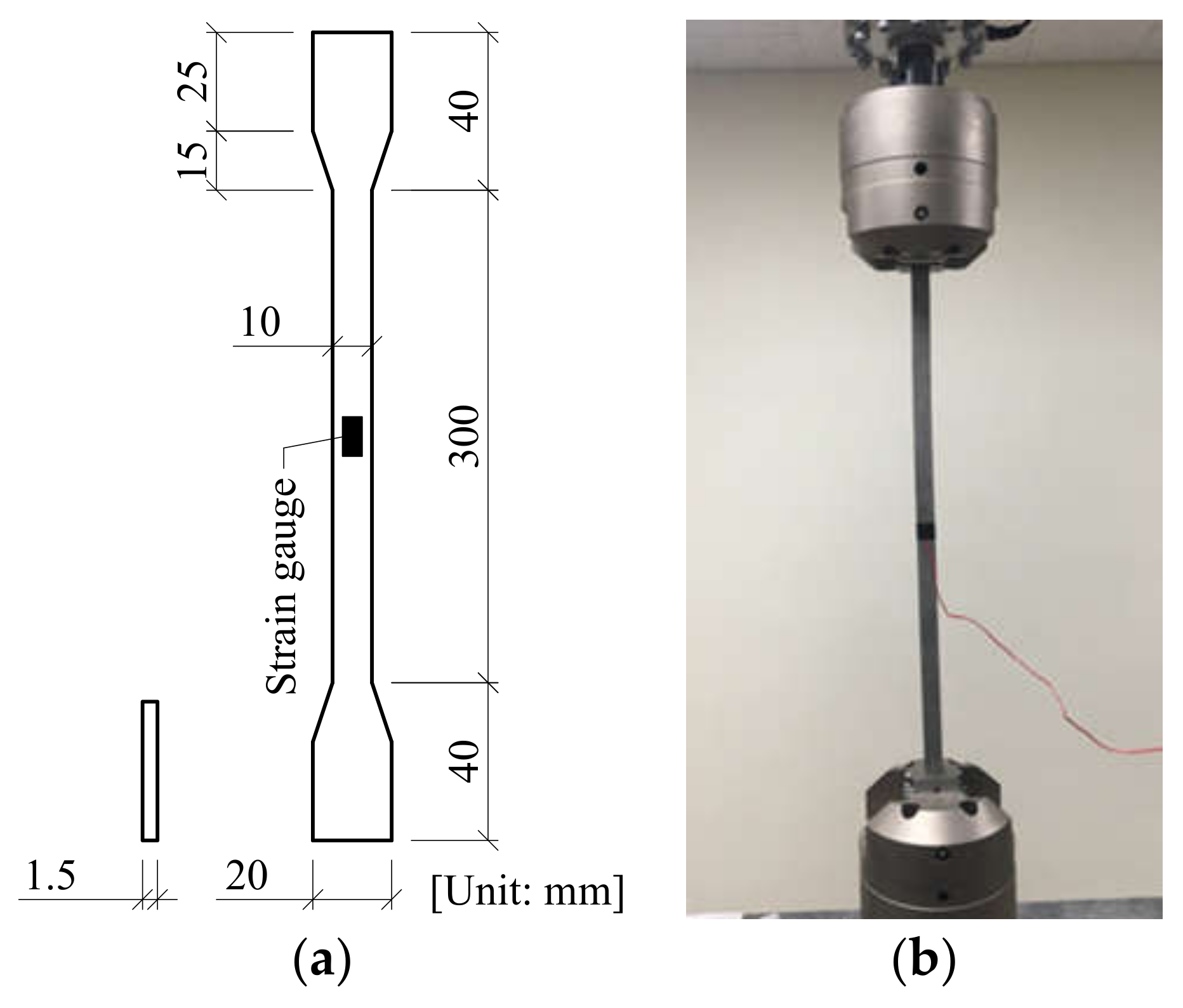
2.3. Recovery Stress Test of Fe-SMA

As aforementioned, the Fe-SMA can be changed to its pre-defined shape due to the SME when it is heated. By using this feature of the Fe-SMA, the SME can introduce the compressive stress in the Fe-SMA when its deformation is restrained. The compressive stress is called “recovery stress” in this paper. This recovery stress was assessed under restrained strain on the different pre-strained Fe-SMAs and the different recovery temperatures. An electric resistance heating was generated by passing the electrical voltage of 2 A/mm2 throughout the Fe-SMA from copper clips connected to a power supply system, as shown in Figure 3.
Before heating the Fe-SMA, the pre-tensile stress of approximately 50 MPa was applied on the Fe-SMA to prevent buckling failure due to the thermal expansion effect on it during the heating. The pre-tensile stress of 50 MPa was conservatively calculated using the coefficient of thermal-expansion of the Fe-SMA. The pre-strained Fe-SMAs were heated up to the target temperature (110 to 220 with an interval of 30 ) to activate the SME by resistive electronic heating. At the mid-length of the Fe-SMA specimen, a K-type thermocouple was attached to measure the recovery temperature on the surface. The test variables are given in Table 1 and the specimen name presents the pre-strained value of “PS” and the recovery temperature of “T”.

2.4. Bonding Test of Fe-SMA

A bonding test was chosen to evaluate the bond behavior and strength of the Fe-SMA embedded in a concrete block with bonding lengths, pre-strained values, and recovery temperatures as experimental variables. The used concrete block size was 130 mm × 150 mm × 500 mm and had the modulus of elasticity and the compressive strength of 30.48 GPa and 42.4 MPa after 28 curing days, respectively. After curing for 28 days, a groove was pre-cut along the length of the concrete block on one surface using a grooving machine. The groove had depth and width of 30 mm and 1.5 mm, respectively. The Fe-SMA had a nominal thickness of 1.5 mm and width of 20.0 mm, and was elongated up to the target strain level, then was inserted in the groove with rubber pads to centrally align it. The groove of the concrete block was filled with a cement-based mortar with the compressive strength of 87.62 MPa. The recovery temperature was measured by K-type thermocouple installed at the mid-height of the Fe-SMA at the casting step. For the bonding test, the concrete block was held by a steel cage and the test setup is shown in Figure 4b.
With the loading rate of 0.25 mm/min, the tensile load was applied under the displacement control. Bonding strength and corresponding slippage values were recorded from the load cell equipped inside the test machine and Linear Variable Differential Transformers (LVDTs).
The experimental variables are given in Table 2. The specimen name indicates that the first initial “L” means the bond length, the second initials “PS” mean the pre-strained values, and the last initial “T” represents the recovery temperature.

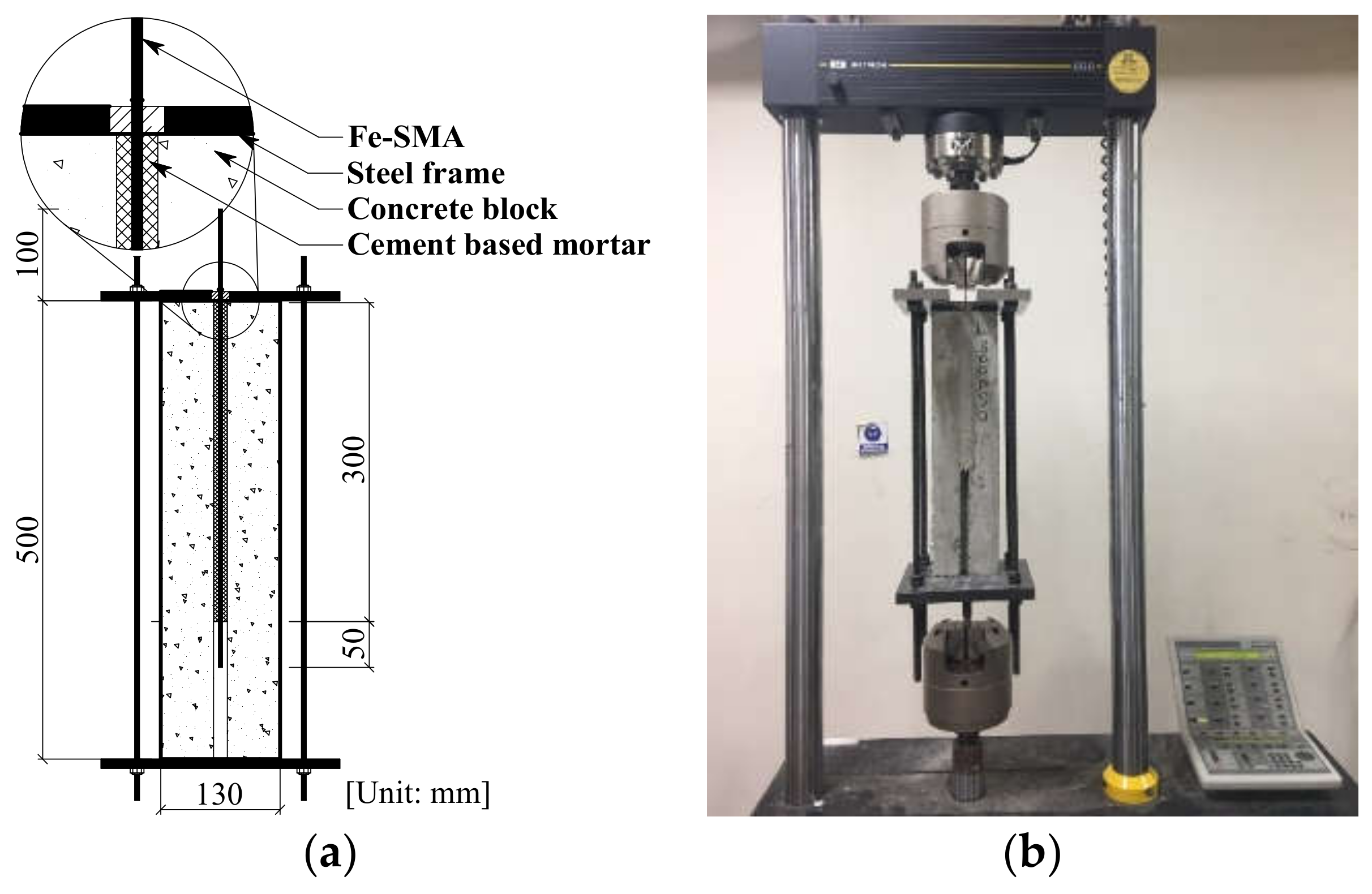
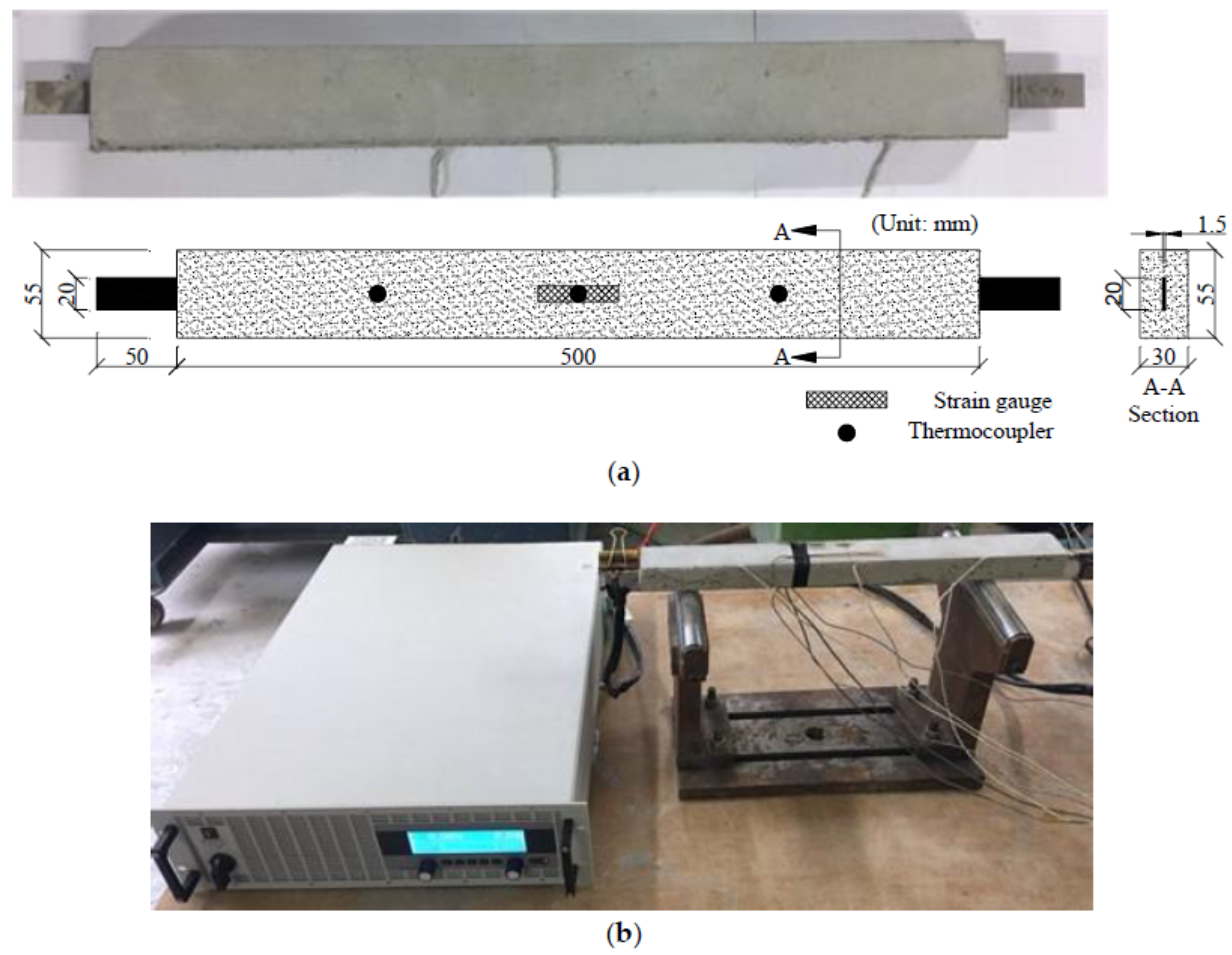
2.5. Recovery Stress Transfer Test

To measure the compressive stress on a concrete member transferred from the Fe-SMA of which the SME activated, a cement-based mortar bar was prepared and tested as shown in Figure 5a. The dimensions of the cement-based mortar bar were with the width 55 mm, thickness 30 mm, and length 500 mm, respectively and the compressive strength of it was 87.67 MPa. The embedded Fe-SMA had dimensions of width, thickness, and length 20 mm, 1.5 mm, and 600 mm, respectively and was pre-strained to 4% at ambient temperature. To prevent crack development on the surface of the cement-based mortar bar due to the thermal expansion of the Fe-SMA, steel fibers with dimensions of 0.5 mm and 30 mm in diameter and length, respectively, were mixed with 2% by volume of the specimen bar. The SME of the Fe-SMA was activated by the resistive electronic heating with the relatively high density of 2 A/mm2 from the power supply system with a capacity of 510 A. The K-type thermocouples were attached on the Fe-SMA to measure the recovery temperature at the mid-length. In addition, two strain gauges were attached on the top and lateral side surfaces at the mid-length of the cement-based mortar bar to measure the elongation strain of the specimen due to either thermal expansion effect or thermal contraction effect from the heated Fe-SMA. The recovery temperatures ranging from 100 to 190 with increments of 30 were considered as experimentally variable and are given in Table 3.

3. Results and Discussion

3.1. Pre-Straining of Fe-SMA

Stress-strain responses on different pre-strain levels are shown in Figure 6. The variance of the stress-strain responses at each pre-strain level on Figure 6 might be because of the microstructure changes due to the initial defects during alloy casting and the temperature difference during pressing [10]. Moreover, in contrast with the mechanical behavior of a normal steel material, no distinguished yielding point was shown on behavior of the Fe-SMA material as shown in Figure 6. This is because the Fe-SMA shows the plastic deformation and the phase transformation from austenite phase to martensite phase during the activation of the SME by resistive electronic heating [10]. Due to difficulty in defining the stress-induced transformation ( σ 0.2 ) on the stress-strain diagram of the Fe-SMA, 0.2% offset point was arbitrarily set to define the modulus of elasticity, which shows the averaged modulus of elasticity of 133 GPa and the averaged stress induced transformation of 463 MPa. The stresses at the fracture of the Fe-SMA were 640 MPa, 691 MPa, 697 MPa, and 742 MPa at 2%, 4%, 6% and 8% of the pre-straining levels, respectively, which shows the increasing stresses by the averaged 5.1%. The stress and strain results are summarized in Table 4.
After the strain of the specimen reached the target pre-strain level, the load was removed at a rate of 0.25 mm/min until the residual stress became zero to measure the residual strain. As shown in Figure 6, at the beginning of the unloading, the stress was reduced from the ultimate stress to 60% with same inclination of the initial modulus of elasticity, and the strain was recovered by the reverse transformation as pseudoelastic strain [9,22]. The residual strains of the specimens were 1.07%, 2.90%, 4.72% and 6.52% for 2% to 8% of pre-strains, respectively, which shows 1.19% of the average recovered strain. The relationship between the recovered strain and pre-strain values showed a linear tendency with a slope and an intercept of 0.9234 and −0.7696, respectively. Around 99.5% of recovered strain values can be explained by the pre-strain values with the mentioned linear tendency.
To investigate the effect of the pre-strain levels on the modulus of elasticity of the Fe-SMA, the un-loaded Fe-SMAs after being stretched up to the target strain were heated to induce the recovery stress and were re-loaded with the direct tensile test. Figure 7 shows the modulus of elasticity of 120.93 GPa, 108.90 GPa, 97.82 GPa and 88.22 GPa, respectively. The modulus of elasticity was decreased by an average of 9.3% with increase in the pre-strains from 2% to 8%. At 2% pre-strained Fe-SMA, modulus of elasticity of the Fe-SMA with activated SME was 120.93 GPa, which is lower than the 173 GPa reported in [32].

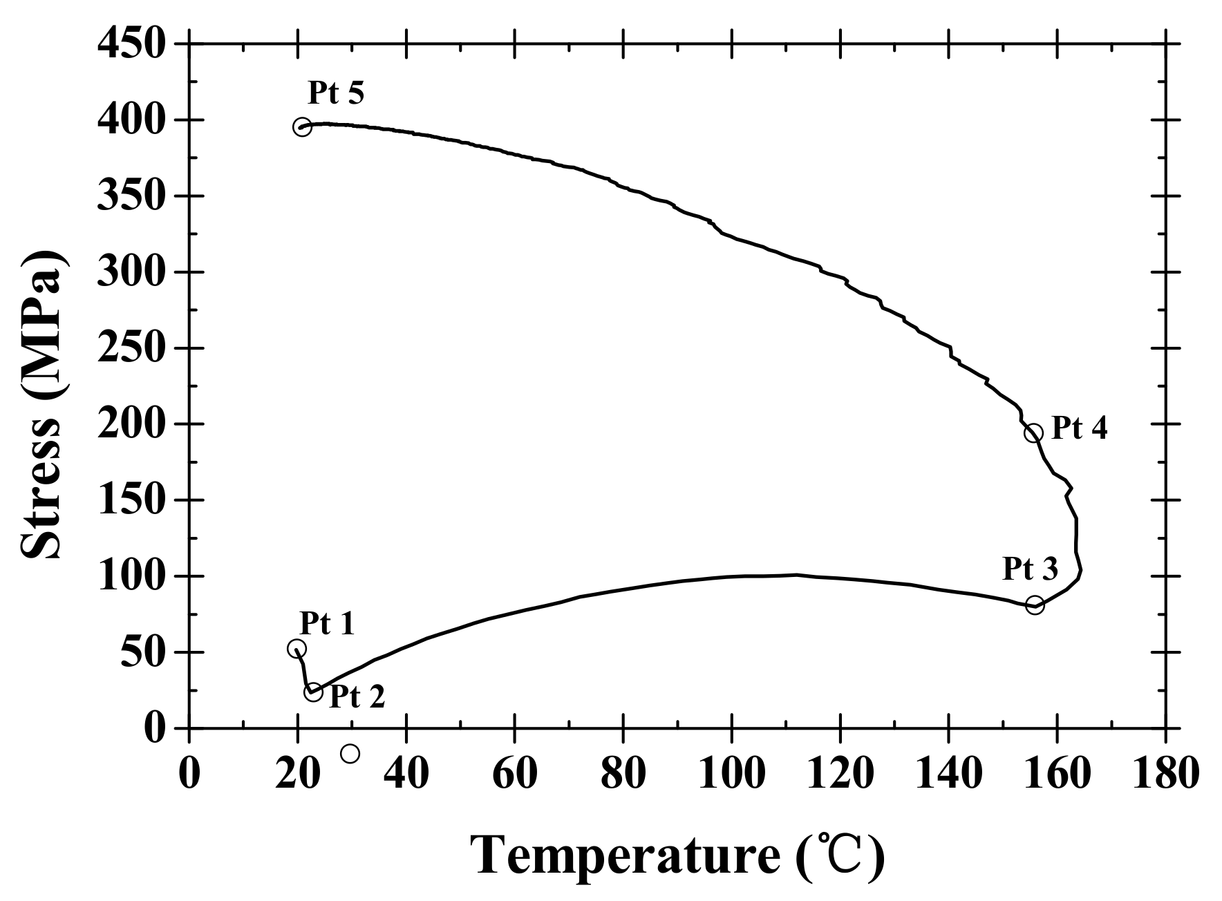
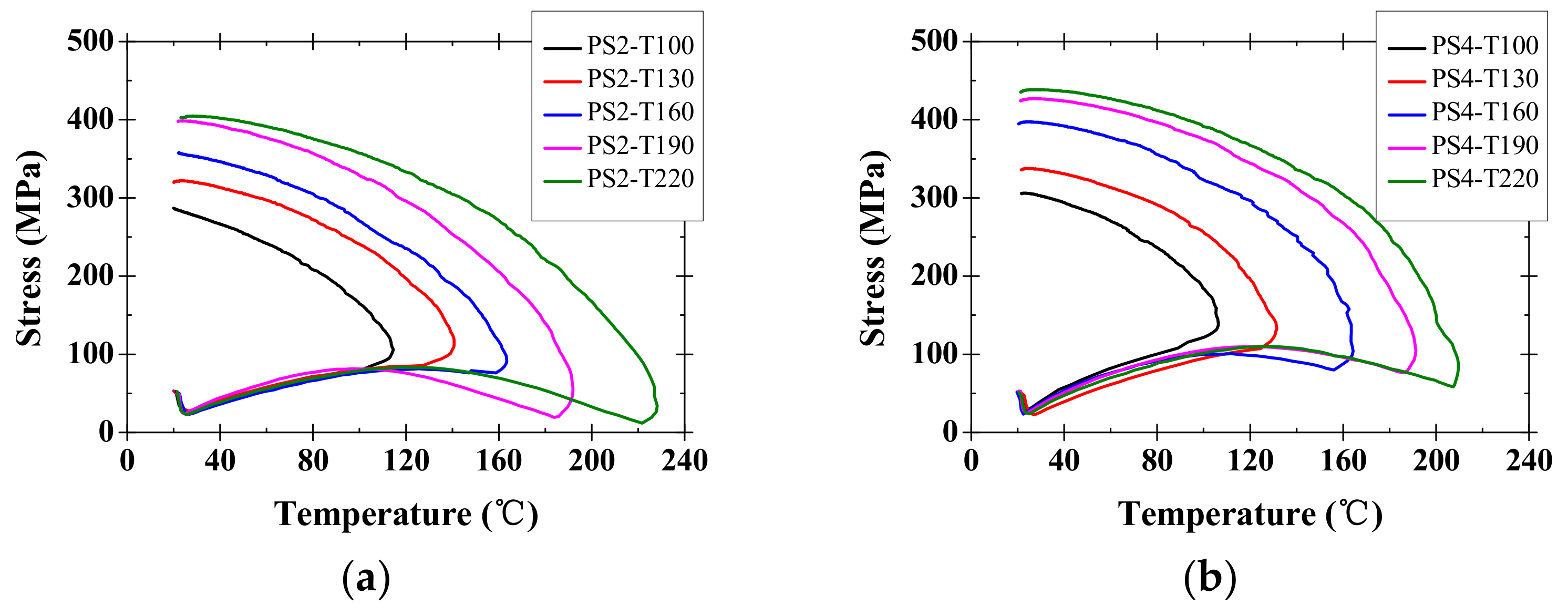
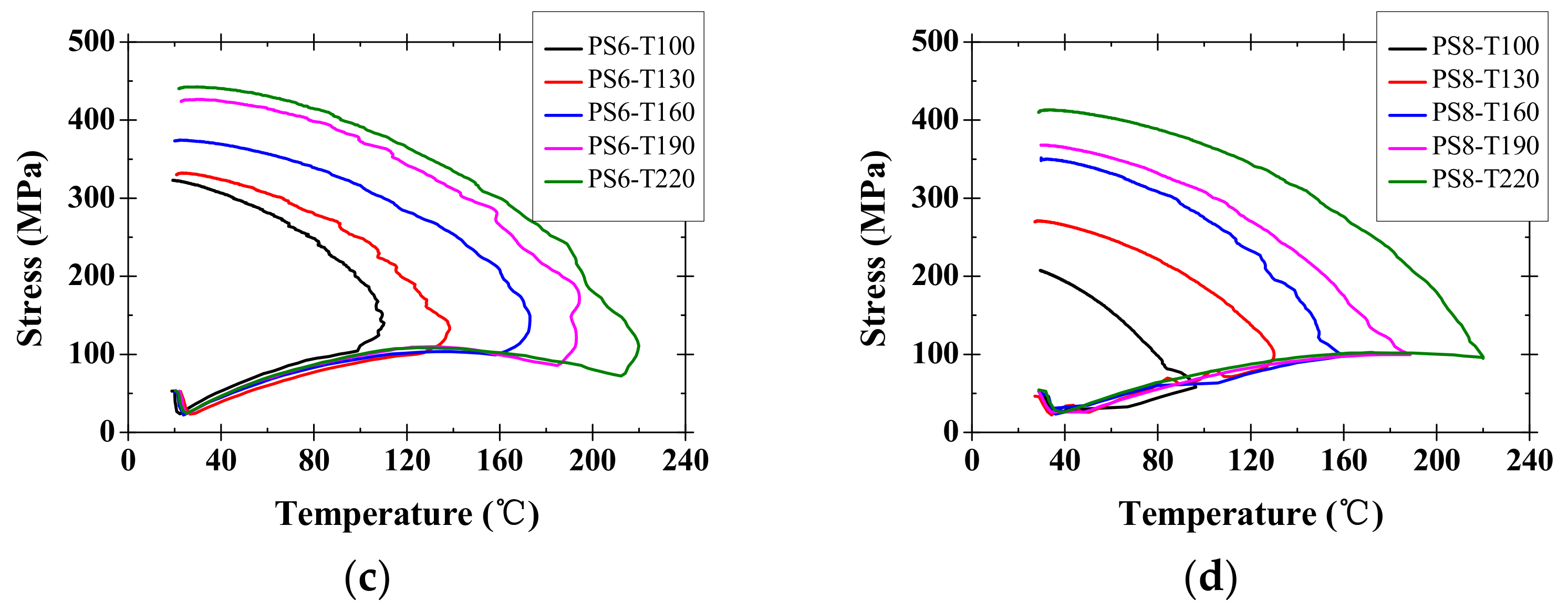
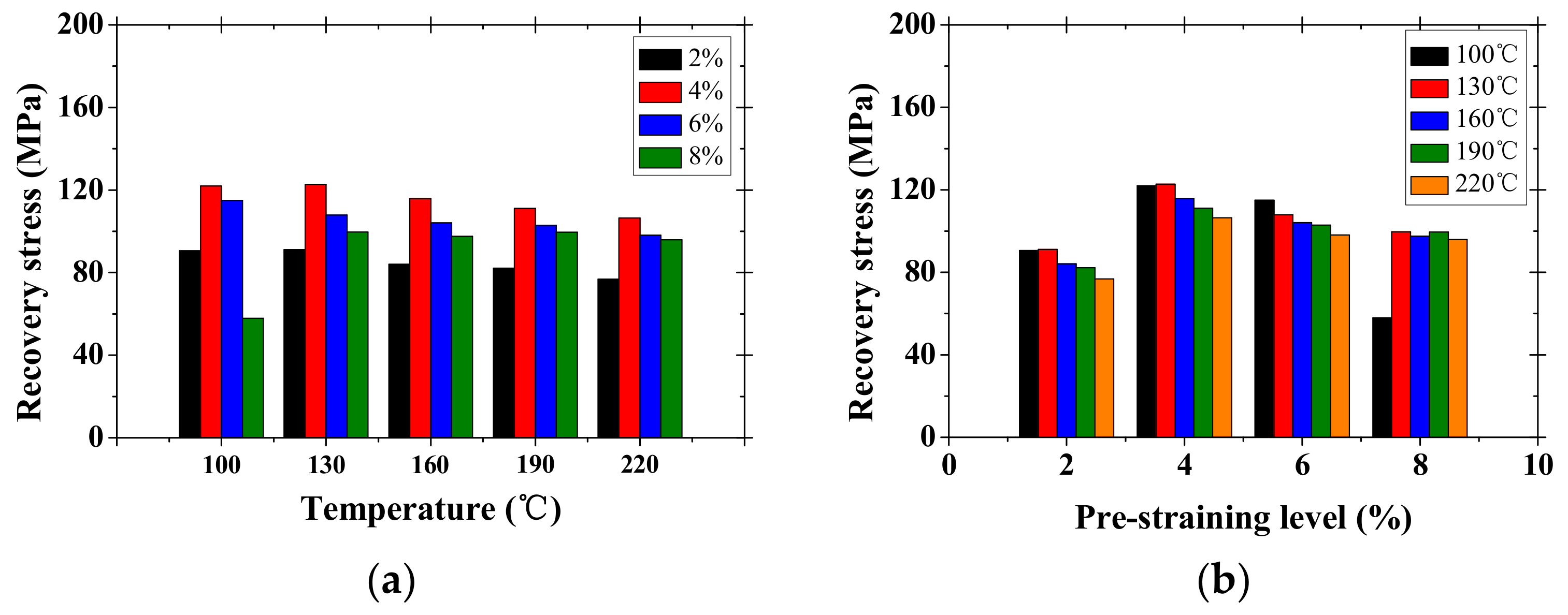
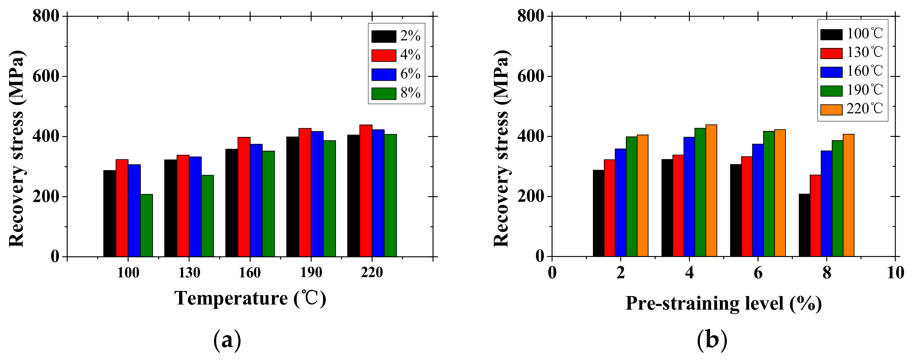
3.2. Recovery Stress Test of Fe-SMA

Figure 8 shows the typical temperature-recovery stress behavior of Fe-SMA in this paper.
The recovery stress diagram is divided into four connected segments: (1) from points 1 to 2 is thermal expansion on the specimen; (2) from points 2 to 3 is heating the specimen; while (3) from points 3 to 4; and (4) from points 4 to 5 are cooling the specimen. The recovery stress from points 1 and 2 was decreased due to the thermal expansion effect on the Fe-SMA during temperature increase. By comparing the thermal coefficient of typical steel material of 1.0 × 10 5 1 , the Fe-SMA remaining in austenitic microstructure has the 60% larger coefficient of thermal expansion, 1.6 × 10 5 1 . This is the reason for the recovery stress being decreased [10]. The recovery stress was increased back to 100 MPa at 100 due to the SME effect and was decreased again to 80 MPa at the targeted 160 due to the thermal expansion. After reaching the target temperature of 160 , the thermal contraction effect increased the recovery stress to the point of 4 during cooling of the Fe-SMA to the ambient temperature. The inclination of the recovery stress and temperature is parallel to the initial dropping inclination at the points between 1 and 2 because of similar coefficients of thermal expansion and modulus of elasticity of the Fe-SMA [10]. The points between 4 and 5 show decreased inclination because the partial phase transformation that occurred on the Fe-SMA from austenite phase to martensite phase [9].
The recovery stresses induced by the activated SME of the Fe-SMA are plotted on different recovery temperatures from 100 to 220 and different pre-strained values from 2% to 8% in Figure 9. As shown in Figure 9 and Table 4, the recovery stress increases linearly with the recovery temperature on all the pre-strained specimens. Ghafoori reported the fatigue behavior of the Fe-SMA and reported the recovery stress of 372 MPa on the 2% pre-strained Fe-SMA at 160 , referred to as “recovery temperature” in this paper [32]. The recovery stress reported in [32] is somewhat higher than obtained from this paper with 2% pre-strained Fe-SMA and 160 heating temperature.
In the case of the pre-strain level variable, the 6% or over pre-strained specimen shows somewhat reduced recovery stress when compared to 4% pre-strained one. The recovery stress of 8% pre-strained specimen was significantly lower than that of 6% pre-strained specimens. This is because the modulus of elasticity of specimen decreases with the pre-strain increases, as aforementioned in Figure 7. Additionally, with all pre-strained specimens on the 190 and 220 temperatures, the recovery stresses did not show any significant increase. This phenomenon is related to the hysteresis behavior of the Fe-SMA material at different temperatures. The SMA materials have four specific temperatures: martensite start and finish temperatures (Ms and Mf) and austenite start and finish temperatures (As and Af). After the temperature reaches the Af, the deformation of the specimen is a constant, which causes a constant recovery stress. For this reason, the recovery stress was not increased linearly after the recovery temperature went over 190 .
As shown in Figure 10a, at the target temperature on all the pre-strained specimens, the recovery stress tends to decrease with the recovery temperature increases because the thermal expansion effect of the Fe-SMAs were governed rather than the SME. However, on the contrary, the fully recovered stresses after the heating-cooling process was completed show an increasing trend when the recovery temperature increased (see Figure 11a). As previously mentioned, below 190 of the activation temperature, the recovery stresses were increased. However, an activation temperature on the Fe-SMA of over 160 may cause microcracks in the surrounding concrete, resulting in the delay of the normal formation of ettringite [33]. Therefore, it would be considered that the recovery temperature of 160 is suitable to induce the recovery stress of the Fe-SMA inside the concrete.
Considering the recovery stresses on the pre-strain levels, the recovery stresses were decreased to 4% of the pre-strained specimens when the temperature reached the target temperatures (see Figure 10b) and were completely cooled (see Figure 11b). This might be because of the decreased modulus of elasticity with higher pre-strained specimens, as aforementioned in Figure 7.

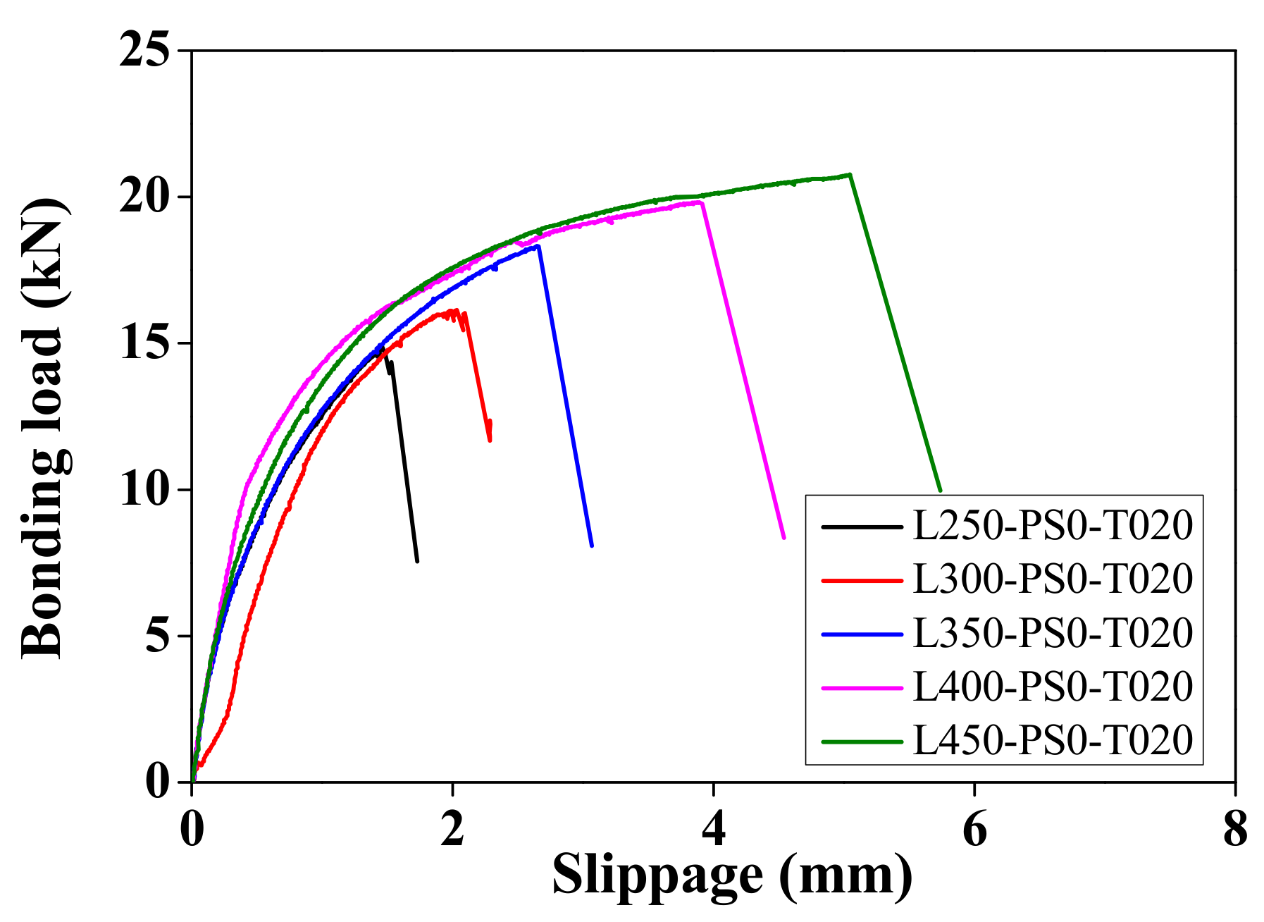
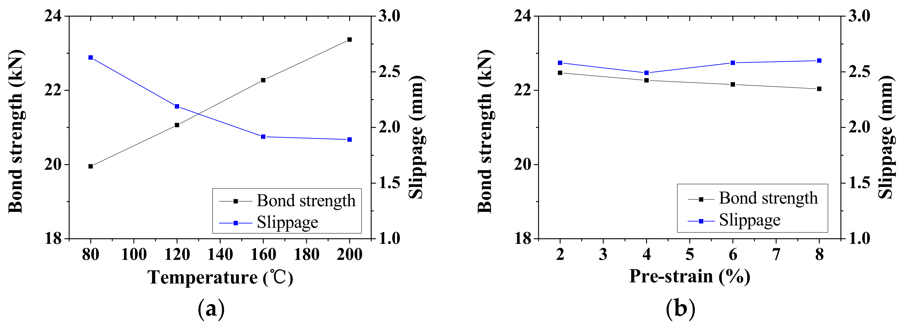
3.3. Bonding Test of Fe-SMA

The slippage failures occurred in the all the specimens at the ultimate bonding strength, which occurred because of the less shear strength at the interface between the Fe-SMA and the cement-based mortar than the yield strength of the Fe-SMA. Furthermore, the feasibility of the Fe-SMA inside the concrete block was evaluated based on the below Equation (1). The feasibility index (F.I.) is expressed in Equation (1).
F . I .   =   σ max f ult . × 100
where, F.I. is a feasibility index, σmax is the maximum tensile stress of the Fe-SMA from the bonding test, and fult is the ultimate tensile stress of the Fe-SMA from the material test. The bonding strength, slippage, and F.I. are given in Table 5.
Figure 12 shows the bonding strength and slip deformation responses according to the bonding lengths of the Fe-SMAs inside the concrete blocks. The bonding strength and F.I. were linearly proportional to the bonding length. The bonding strength and F.I. are improved by an average of 8.8% as the bonding length of the specimen increased from 250 mm to 450 mm. Because of linear regression analysis based on the bonding length and the F.I., the required bonding length of the Fe-SMA to introduce fully pre-stressing force on the concrete is over 600 mm.
Figure 13 shows the bonding strengths and the slippage on different recovery temperatures and different pre-stained values of the embedded Fe-SMAs. The bonding strengths linearly increase by an average of 5.1% with the recovery temperature (see Figure 13a). With this result, it can be mentioned that the Fe-SMA at the high recovery temperature maintains the sufficient bonding strength. Additionally, there is no significant difference on the bond strengths with increase in the pre-strained Fe-SMAs, as shown in Figure 13b. This is because that the pre-strained Fe-SMAs have similar recovery stresses on different pre-strained values. However, the slippage occurrence of the Fe-SMA, referred as “slippages” in Figure 13, shows somewhat different results, compared to the bonding strength. In Figure 13a, after increasing the recovery temperatures, the slippages showed decreases. This might be closely related to the recovery stress. The higher recovery stress accounted for the tensile strength, which resulted in lower slippages. In Figure 13b, the slippages on the different pre-strained values of the Fe-SMAs happened at the deformation of around 2.6 mm. This is because the recovery stresses of those specimens were gathered around the average of 370.40 MPa.

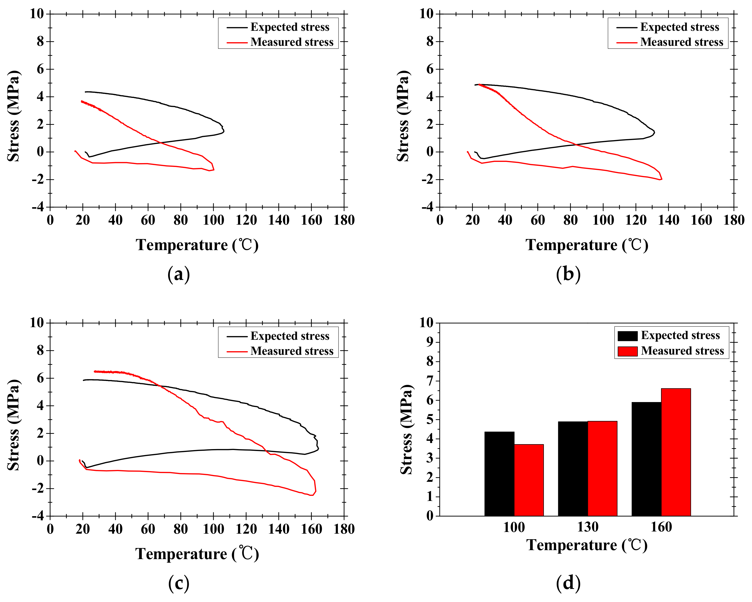
3.4. Result of Recovery Stress Transfer Test for Cement-Based Mortar Bar

Behavior of the cement-based mortar bar containing the Fe-SMA was investigated to calculate a compressive strength on surrounding concrete transferred from the Fe-SMA. As mentioned previously, in the recovery stress of the Fe-SMA, the Fe-SMA with the activated SME under constrained strain by the cured concrete generated the recovery stress which would be used as the pre-stressing force. The measured elongation on the surface of the cement-based mortar bar by the strain gauge was used to calculate the measured compressive stress, σmeasured. The measured strength of the cement-based mortar bar was computed with the equivalent modulus of elasticity and obtained strains, as expressed in Equation (2) below.
σ measured = Δ l l o E e q
in which Eeq is an equivalent Young’s modulus of elasticity and lo is the original length of the Fe-SMA.
In addition, the expected compressive stress, σexpected, was calculated with the recovery stress from the thermal mechanical properties of Fe-SMA. The expected compressive strength of the Fe-SMA is calculated by Equation (3) below.
σ expected = σ r . s . × A Fe SMA A eq
where AFe-SMA is an area of the Fe-SMA strip, Aeq is the cross-sectional area of mortar bar, and σ r . s . is the recovery stress by the SME of the Fe-SMA at the 160 of the recovery temperature.
Figure 14 shows comparisons between the expected compressive stress from the Fe-SMA (black solid line) and the measured compressive stress from the cement-based mortar bar (red solid line) on different recovery temperatures. During the activation of the SME, the difference of two compressive stress responses was remarkably shown. This is because of the thermal expansion effect on the mortar bar. The heating for the activation of the SME was transferred to the surrounding cement mortar bar, which makes the cement-based mortar bar expand. Because the mortar strain was assessed from the strain gauge which was attached on the surface of the specimen bar, a strain could be measured that was higher than the surface strain of the Fe-SMA.
The compressive stresses of the cement-based mortar bar and the Fe-SMA increased by 25% with the increased activation temperature. At higher recovery temperature than 160 applied to the mortar bar, the high heat of the Fe-SMA was transferred to the mortar surrounding the strip, which generated longitudinal cracks along the Fe-SMA. Furthermore, the recovery temperature higher than 160 delays a formation of ettringite at the interface between the cement and fine aggregate, or destroys the formation of ettringite, which generates crack development [33].
According to the results of the recovery stress transfer test, it is confirmed that the pre-stressing force applied on the concrete member would be estimated by the recovery stress of the Fe-SMA. Furthermore, these results obtained from these tests suggest that the optimum recovery temperature is 160 for the introduction of the pre-stressing force on the concrete.

4. Conclusions

In this paper, thermal-mechanical properties of a Fe-based shape memory alloy (Fe-SMA) were investigated for use as strengthening material for civil structures. Based on results from material tests, conclusions can be drawn as follows:
(1)
The Fe-SMA shows sufficient potential to be applied as strengthening material when retrofitting damaged structures or strengthening civil structures. By applying a electric resistive heating temperature of 160 , the 4% pre-strained Fe-SMA embedded inside the concrete would show the shape memory effect (SME), which induces a compressive force on concrete. This compressive force plays an important role as the pre-stressing force on concrete structures.
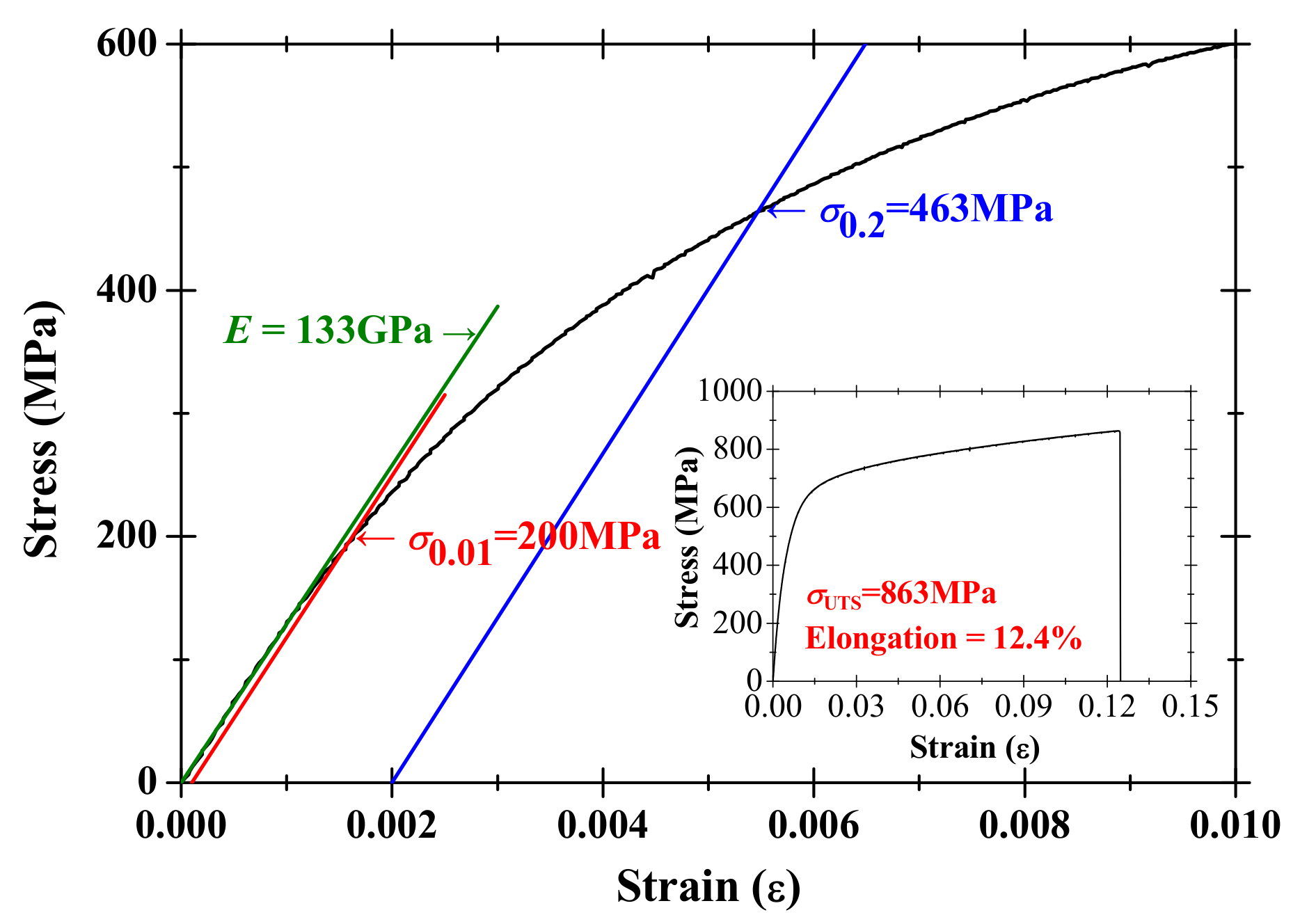
(2)
From the direct tensile tests of the Fe-SMA, the limit of proportionality stress, the 0.2% offset stress, and the modulus of elasticity were 463 MPa, 863 MPa, and 133 GPa, respectively. Based on these mechanical properties, the recovery stresses of the Fe-SMA by the SME activation at recovery temperature from 100 to 220 range linearly from 207.59 MPa to 438.61 MPa, which is transferred to the surrounding concrete as the pre-stressing force.
(3)
The bonding strength and feasibility index of the Fe-SMAs were improved by an average of 8.8% with an increased embedding length from 250 mm to 450 mm. The regression analysis based on the feasibility index and bonding length of the Fe-SMA indicates that the pre-stressing force can be fully developed when the embedded length is over 600 mm.
(4)
Based on the recovery stress transfer tests, the amount of pre-stressing force applied on strengthened concrete structures could be estimated by the recovery stress of the Fe-SMA.

Author Contributions

Yeongmo Yeon conducted the experiments and Ki-Nam Hong wrote the initial draft of the manuscript. Ki-Nam Hong, Sugyu Lee, and Sanghoon Han analyzed the data and wrote the final manuscript. All authors contributed to the analysis of the data and read the final paper.

Funding

This work is supported by the Korea Agency for Infrastructure Technology Advancement (KAIA) grant funded by the Ministry of Land, Infrastructure and Transport (Grant #115171).

Acknowledgments

This work is supported by the Korea Agency for Infrastructure Technology Advancement (KAIA) grant funded by the Ministry of Land, Infrastructure and Transport (Grant #115171). In addition, authors would like to acknowledge the support from the re-fer AG Company in Switzerland for providing the Fe-SMA material for this research.

Conflicts of Interest

The authors declare no conflict of interest.

References

  1. Chang, L.C.; Read, T.A. Plastic deformation and diffusionless phase changes in metals—The gold-cadmium beta phase. JOM 1951, 3, 47–52. [Google Scholar] [CrossRef]
  2. Buehler, W.J.; Gilfrich, J.V.; Wiley, R.C. Effect of low-temperature phase changes on the mechanical properties of alloys near composition TiNi. J. Appl. Phys. 1963, 34, 1475–1477. [Google Scholar] [CrossRef]
  3. Hodgson, D.E.; Ming, W.H.; Biermann, R.J. Shape memory alloys. In ASM International, Metals Handbook, 10th ed.; ASM International: Almere, The Netherlands, 1990; Volume 2. [Google Scholar]
  4. Cederström, J.; Humbeeck, J.V. Relationship between shape memory material properties and applications. J. Phys. 1995, 5, C2-335. [Google Scholar] [CrossRef]
  5. Wilkes, K.E.; Liaw, P.K. The fatigue behavior of shape-memory alloys. JOM 2000, 52, 45–51. [Google Scholar] [CrossRef]
  6. Cladera, A.; Weber, B.; Leinenbach, C.; Czaderski, C.; Shahverdi, M.; Motavalli, M. Iron-based shape memory alloys for civil engineering structures: An overview. Constr. Build. Mater. 2014, 63, 281–293. [Google Scholar] [CrossRef]
  7. Melton, K.N.; Mercier, O. The mechanical properties of NiTi-based shape memory alloys. Acta Metall. 1981, 29, 393–398. [Google Scholar] [CrossRef]
  8. Sato, A.; Chishima, E.; Soma, K.; Mori, T. Shape memory effect in γ⇄ϵ transformation in Fe-30Mn-1Si alloy single crystals. Acta Metall. 1982, 30, 1177–1183. [Google Scholar] [CrossRef]
  9. Lee, W.J.; Weber, B.; Feltrin, G.; Czaderski, C.; Motavalli, M.; Leinenbach, C. Phase transformation behavior under uniaxial deformation of an Fe-Mn-Si-Cr-Ni-VC shape memory alloy. Mater. Sci. Eng. A 2013, 581, 1–7. [Google Scholar] [CrossRef]
  10. Czaderski, C.; Shahverdi, M.; Brönnimann, R.; Leinenbach, C.; Motavalli, M. Feasibility of iron-based shape memory alloy strips for prestressed strengthening of concrete structures. Constr. Build. Mater. 2014, 56, 94–105. [Google Scholar] [CrossRef]
  11. Janke, L.; Czaderski, C.; Motavalli, M.; Ruth, J. Applications of shape memory alloys in civil engineering structures—Overview, limits and new ideas. Mater. Struct. 2005, 38, 578–592. [Google Scholar]
  12. Sawaguchi, T.; Sahu, P.; Kikuchi, T.; Ogawa, K.; Kajiwara, S.; Kushibe, A.; Higashino, M.; Ogawa, T. Vibration mitigation by the reversible fcc/hcp martensitic transformation during cyclic tension–compression loading of an Fe-Mn-Si-based shape memory alloy. Scr. Mater. 2006, 54, 1885–1890. [Google Scholar] [CrossRef]
  13. Yang, J.H.; Wayman, C.M. Development of Fe-based shape memory alloys associated with face-centered cubic-hexagonal close-packed martensitic transformations: Part III. microstructures. Metall. Trans. A 1992, 23, 1445–1454. [Google Scholar] [CrossRef]
  14. Otsuka, H.; Yamada, H.; Maruyama, T.; Tanahashi, H.; Matsuda, S.; Murakami, M. Effects of alloying additions on Fe-Mn-Si shape memory alloys. ISIJ Int. 1990, 30, 674–679. [Google Scholar] [CrossRef]
  15. Rong, L.J.; Ping, D.H.; Li, Y.Y.; Shi, C.X. Improvement of shape memory effect in Fe-Mn-Si alloy by Cr and Ni addition. Scr. Metal. Mater. 1995, 32. [Google Scholar] [CrossRef]
  16. Wang, Z.; Zu, X.; Feng, X.; Dai, J. Effect of thermomechanical treatment on the two-way shape memory effect of NiTi alloy spring. Mater. Lett. 2002, 54, 55–61. [Google Scholar] [CrossRef]
  17. Gu, Q.; Humbeeck, J.V.; Delaey, L.; Federzoni, L.; Guénin, G.; Gex, D. Effect of amount of deformation on the martensitic transformation and shape memory effect in Fe-Mn-Si based shape memory steel. J. Phys. 1995, 5, C2-311. [Google Scholar] [CrossRef]
  18. Rojob, H.; El-Hacha, R. Self-Prestressing Using Iron-Based Shape Memory Alloy for Flexural Strengthening of Reinforced Concrete Beams. ACI Struct. J. 2017, 114, 523. [Google Scholar] [CrossRef]
  19. Kajiwara, S.; Liu, D.; Kikuchi, T.; Shinya, N. Remarkable improvement of shape memory effect in Fe-Mn-Si based shape memory alloys by producing NbC precipitates. Scr. Mater. 2001, 44, 2809–2814. [Google Scholar] [CrossRef]
  20. Farjami, S.; Hiraga, K.; Kubo, H. Shape memory effect and crystallographic investigation in VN containing Fe-Mn-Si-Cr alloys. Mater. Trans. 2004, 45, 930–935. [Google Scholar] [CrossRef]
  21. Dong, Z.; Klotz, U.E.; Leinenbach, C.; Bergamini, A.; Czaderski, C.; Motavalli, M. A Novel Fe-Mn-Si Shape Memory Alloy with Improved Shape Recovery Properties by VC Precipitation. Adv. Eng. Mater. 2009, 11, 40–44. [Google Scholar] [CrossRef]
  22. Leinenbach, C.; Kramer, H.; Bernhard, C.; Eifler, D. Thermo-Mechanical Properties of an Fe-Mn-Si-Cr-Ni-VC Shape Memory Alloy with Low Transformation Temperature. Adv. Eng. Mater. 2012, 14, 62–67. [Google Scholar] [CrossRef]
  23. Hsu, T.Y.; Zuyao, X. Martensitic transformation in Fe-Mn-Si based alloys. Mater. Sci. Eng. A 1999, 273, 494–497. [Google Scholar] [CrossRef]
  24. Lagoudas, D.C. (Ed.) Shape Memory Alloys: Modeling and Engineering Applications; Springer Science & Business Media: Berlin, Germany, 2008. [Google Scholar]
  25. Watanabe, Y.; Mori, Y.; Sato, A. Training effect in Fe-Mn-Si shape-memory alloys. J. Mater. Sci. 1993, 28, 1509–1514. [Google Scholar] [CrossRef]
  26. Maji, A.K.; Negret, I. Smart prestressing with shape-memory alloy. J. Eng. Mech. 1998, 124, 1121–1128. [Google Scholar] [CrossRef]
  27. Krstulovic-Opara, N.; Naaman, A.E. Self-stressing fiber composites. Struct. J. 2000, 97, 335–344. [Google Scholar]
  28. Soroushian, P.; Ostowari, K.; Nossoni, A.; Chowdhury, H. Repair and strengthening of concrete structures through application of corrective posttensioning forces with shape memory alloys. Transp. Res. Rec. J. Transp. Res. Board 2001, 1770, 20–26. [Google Scholar] [CrossRef]
  29. Deng, Z.; Li, Q.; Sun, H. Behavior of concrete beam with embedded shape memory alloy wires. Eng. Struct. 2006, 28, 1691–1697. [Google Scholar] [CrossRef]
  30. Moser, K.; Bergamini, A.; Christen, R.; Czaderski, C. Feasibility of concrete prestressed by shape memory alloy short fibers. Mater. Struct. 2005, 38, 593–600. [Google Scholar] [CrossRef]
  31. Hosseini, E.; Ghafoori, E.; Leinenbach, C.; Motavalli, M.; Holdsworth, S.R. Stress recovery and cyclic behaviour of an Fe-Mn-Si shape memory alloy after multiple thermal activation. Smart Mater. Struct. 2018, 27, 025009. [Google Scholar] [CrossRef]
  32. Ghafoori, E.; Hosseini, E.; Leinenbach, C.; Michels, J.; Motavalli, M. Fatigue behavior of a Fe-Mn-Si shape memory alloy used for prestressed strengthening. Mater. Des. 2017, 133, 349–362. [Google Scholar] [CrossRef]
  33. Park, S.; Yim, H.J.; Kwak, H.K. Evaluation of microcracks in thermal damaged concrete using nonlinear ultrasonic modulation technique. J. Korea Concr. Inst. 2012, 24, 651–658. [Google Scholar] [CrossRef]
Figure 1. Stress-strain curve of direct tensile test.
Applsci 08 00730 g001
Figure 2. Pre-straining process: (a) Detailed view of specimen; (b) Pre-straining setup.
Applsci 08 00730 g002
Figure 3. Electronic power supplying.
Applsci 08 00730 g003
Figure 4. Bonding test setup: (a) Detailed of bonding test specimen; (b) Bonding test setup.
Applsci 08 00730 g004
Figure 5. Recovery stress transfer test: (a) Cement-based mortar bar containing Fe-SMA; (b) Test setup of recovery stress transfer.
Applsci 08 00730 g005
Figure 6. Pre-straining of Fe-SMA specimens: (a) 2% of pre-strain; (b) 4% of pre-strain; (c) 6% of pre-strain; (d) 8% of pre-strain.
Applsci 08 00730 g006
Figure 7. Modulus of elasticity of pre-strained Fe-SMA with activated SME.
Applsci 08 00730 g007
Figure 8. Stress-temperature diagram of a heating and cooling cycle on 4% pre-strained Fe-SMA with the recovery temperature of 160 °C.
Applsci 08 00730 g008
Figure 9. Recovery stress with different resistive recovery temperatures: (a) 2% of pre-strain; (b) 4% of pre-strain; (c) 6% of pre-strain; (d) 8% of pre-strain.
Applsci 08 00730 g009aApplsci 08 00730 g009b
Figure 10. Recovery stress at target temperature: (a) Activation temperature of SME; (b) Pre-strain value.
Applsci 08 00730 g010
Figure 11. Recovery stress after completed cooling down: (a) Activation temperature of SME; (b) Pre-strain value.
Applsci 08 00730 g011
Figure 12. Bonding strength and slippage responses.
Applsci 08 00730 g012
Figure 13. Bond strengths on different temperature and pre-strained values: (a) Different recovery temperatures on L300-PS4 specimens; (b) Different pre-strained values on L300-T160 specimens.
Applsci 08 00730 g013
Figure 14. Compressive stress on different recovery temperatures: (a) recovery temperature of 100 ; (b) recovery temperature of 130 ; (c) recovery temperature of 160 ; (d) comparison of expectation and measurement of compressive stresses.
Applsci 08 00730 g014
Table 1. Details of specimens for recovery stress test.
SpecimenPre-Strain (%)Recovery Temperature ( )
PS2-T1002100
PS2-T1302130
PS2-T1602160
PS2-T1902190
PS2-T2202220
PS4-T1004100
PS4-T1304130
PS4-T1604160
PS4-T1904190
PS4-T2204220
PS6-T1006100
PS6-T1306130
PS6-T1606160
PS6-T1906190
PS6-T2206220
PS8-T1008100
PS8-T1308130
PS8-T1608160
PS8-T1908190
PS8-T2208220
Table 2. Specimens of bonding test.
SpecimenBond Length (mm)Pre-Strained Value (%)Recovery Temperature ( )
L250-PS0-T020250020
L300-PS0-T020300020
L350-PS0-T020350020
L400-PS0-T020400020
L450-PS0-T020450020
L300-PS4-T080300480
L300-PS4-T1203004120
L300-PS4-T1603004160
L300-PS4-T2003004200
L300-PS2-T1603002160
L300-PS4-T1603004160
L300-PS6-T1603006160
L300-PS8-T1603008160
Table 3. Details of variable for cement-based mortar bar specimen.
SpecimenPre-Strain (%)Recovery Temperature ( )
Com-PS4-T1004100
Com-PS4-T1304130
Com-PS4-T1604160
Com-PS4-T1904190
Table 4. Results of recovery stress for Fe-SMA.
SpecimenPre-StrainRecovered StrainMaximum StressRecovery TemperatureRecovery Stress
(%)(%)(MPa)( )(MPa)
PS2-T1001.941.02644.80114.6287.06
PS2-T1301.911.05641.85130.7322.37
PS2-T1601.961.03636.11163.4358.08
PS2-T1902.001.12631.00191.9398.73
PS2-T2201.991.12644.38228.2404.73
PS4-T1003.942.83691.30106.4323.06
PS4-T1304.002.90695.73131.4337.80
PS4-T1604.002.96676.39164.3397.50
PS4-T1904.002.91698.18191.3426.89
PS4-T2204.002.89694.79209.6438.61
PS6-T1006.004.75712.45110.0306.31
PS6-T1306.004.80692.42138.4332.34
PS6-T1606.004.49675.29173.0374.47
PS6-T1906.004.79699.70194.0416.65
PS6-T2206.004.76704.71219.9422.51
PS8-T1008.006.69734.9796.4207.59
PS8-T1308.006.66742.24130.0271.14
PS8-T1608.006.60753.66163.4351.58
PS8-T1908.006.70726.49188.6386.08
PS8-T2208.026.66752.47220.0407.26
Table 5. Results of bonding tests.
SpecimenBond Strength (kN)Slippage (mm)F.I. (%)
L250-PS0-T02014.871.4657.39
L300-PS0-T02018.142.0362.29
L350-PS0-T02018.322.6470.71
L400-PS0-T02019.823.8776.48
L450-PS0-T02020.775.0480.17
L300-PS4-T08019.952.5776.99
L300-PS4-T12021.063.4581.82
L300-PS4-T16022.275.0385.95
L300-PS4-T20023.386.6490.19
L300-PS2-T16022.476.5686.73
L300-PS4-T16022.275.0385.95
L300-PS6-T16022.163.4385.51
L300-PS8-T16022.043.0585.05

