Article

Contact Pressure Algorithm of Multi-Layer Interference Fit Considering Centrifugal Force and Temperature Gradient

Engineering Research Center Heavy Machinery Ministry of Education, Taiyuan University of Science and Technology, Taiyuan 030024, China
*
Author to whom correspondence should be addressed.
Appl. Sci. 2018, 8(5), 726; https://doi.org/10.3390/app8050726
Submission received: 29 March 2018 / Revised: 23 April 2018 / Accepted: 23 April 2018 / Published: 5 May 2018

Abstract

:
In order to optimize the algorithm on contact pressure and interference magnitude of multi-layer interference cylinders, the effects of centrifugal force and temperature gradient on the performance of multi-layer interference cylinders are considered. The mathematical matrix model of contact pressure and interference magnitude of multi-layer interference cylinder is constructed under centrifugal force and temperature gradient. Four kinds of interference cylinder models are established, and the numerical solutions using finite element methods are compared with the analytical solutions. The results show that the contact pressure of each contact surface of multi-layer interference cylinder decreases with speed increase; the slip rate of contact pressure increases with speed increase; the maximum radial displacement of an interference cylinder under centrifugal force occurs at the outermost layer. The contact pressure of a multi-layer interference cylinder decreases linearly with the increase of temperature gradient. The analytical solution is basically consistent with the numerical solution, and the maximum relative error of midpoint is 11.62% and −7.69% under two factors. It means that the algorithm can provide a theoretical guide for the design of a multi-layer interference cylinder considering centrifugal force and temperature gradient.

Graphical Abstract

1. Introduction

The interference fit has the advantages of simple structure, good neutrality, strong load-carrying capacity, good impact resistance, and so on, so it has a wide application in mechanical engineering [1]. Many scholars have done a lot of research on the algorithm and influence of interference fit. Sogalad [2] studied the influence of cylindricity and surface modification on the load-carrying capacity of interference fit components. Zhang et al. [3] analyzed the influence of different influence factors on the dynamic performance of oblique cone interference fit. Compared with the equal diameter cylindrical interference fit, the influence of interference magnitude on the local contact stress is obvious. Wang et al. [4,5] proposed a variety of algorithms for multi-layer interference fit based on thick-wall cylinder theory and analyzed the effects of many factors on the performance of multi-layer interference fit. McMillan [6] studied the phenomenon of torque increase during the loading cycle of the interference specimen. By establishing a cycle wear test, the reason for the torque increase is related to the friction coefficient between interference fit. The research provides a basis for the optimization of interference fit design. Based on the geometric defects and surface roughness of the interference specimen, Boutoutaou H et al. [7,8] studied its influence on the strength of interference connection. Li J et al. [9,10] studied the effect of interference size on the fretting fatigue life of carbon fiber reinforced polymers and titanium alloy bolts.
The interference components usually work at high speed and under a temperature field, various rotational speeds and temperatures have different effects on the performance of interference components. At present, some scholars have made some research in these fields. For example, Kurvinen [11] studied the dynamic characteristics and mechanical properties of ball bearings with or without centrifugal force. Guo [12] established a displacement mathematical model based on centrifugal force and temperature in the bearing inner ring, coupled with the bearing dynamic model of bearing, and studied change rule of bearing interference fit and the influence on spindle system dynamics. The results show that the initial interference magnitude will increase with the combined influence factors of temperature increase and centrifugal force, and eventually lead to the increase of bearing stiffness. Ding [13] analyzed the calculation method of the interference magnitude and stress between the rotor and the permanent magnet, establishing a finite element model for stress analysis, and the results were compared. Zhou [14] established a three-dimensional single-layer interference cylinder model and analyzed influence of centrifugal force on the interference fit. Qiu et al. [15] proposed an algorithm for calculating contact pressure and stress of multi-layer interference fit under multi contact and temperature. An engine crankshaft bearing case was established using finite element method to verify the correctness of its algorithm.
However, the research on the influencing factors of interference fit is mainly concentrated in a single layer. Currently, multi-layer interference fit is widely used in engineering, for example low-speed coupling of wind turbine (Figure 1), which can be used as the typical application of multi-layer interference cylinder [16]. Here, the effects of centrifugal force and temperature gradient on the contact pressure of multi-layer interference cylinder are analyzed. The matrix model of contact pressure and interference magnitude of multi-layer interference cylinder under centrifugal force and temperature gradient is derived. Four kinds of interference cylinder models are built to respectively analyze the influence of centrifugal force and temperature gradient on the performance of multi-layer interference cylinder. By comparing the calculation results of the finite element numerical method and analytic method, some conclusions of the multi-layer interference cylinder are obtained.

2. Algorithm for Multi-Layer Interference Cylinder

According to the Lame equation, the radial displacement of any point in the cylinder can be obtained [17]:
u φ = 1 μ E a 2 p 1 b 2 p 2 b 2 a 2 ρ + 1 + μ E a 2 b 2 ( p 1 p 2 ) b 2 a 2 1 ρ
where a is the inner radius of the cylinder, b is the outer radius of the cylinder, ρ is the radius of any point of cylinder, p 1 is the internal pressure of the cylinder, p 2 is the external pressure of the cylinder, E is the modulus of elasticity, and μ is Poisson ratio.
Figure 2 is the schematic diagram of force on two cylinders with interference fit. C i is defined as cylinder i ; C i + 1 is cylinder i + 1 ; p i 1 is the internal pressure of C i ; p i is the contact pressure between C i and C i + 1 ; p i + 1 is the external pressure of C i + 1 ; r 1 , i is the inner radius of C i ; r 2 , i is the outer radius of C i ; r 2 , i + 1 is the outer radius of C i + 1 ; S is contact surface between C i and C i + 1 .
According to Equation (1), the relation between the radial displacement of contact surface of multi-layer interference cylinder can be obtained. Based on the radial displacement relationship between C i and C i + 1 , a matrix model of multi-layer interference cylinder can be obtained as:
δ = K p
Among them, δ = [ δ 1 , δ 2 , , δ n ] T , p = [ p 1 , p 2 , , p n ] T ,
K = [ ( K 1 , 2 + K 4 , 1 ) K 2 , 2 0 0 0 0 K 3 , 2 ( K 1 , 3 + K 4 , 2 ) K 2 , 3 0 0 0 0 K 3 , 3 ( K 1 , 4 + K 4 , 3 ) K 2 , 4 0 0 0 0 K 3 , n 2 ( K 1 , n 1 + K 4 , n 2 ) K 2 , n 1 0 0 0 0 K 3 , n 1 ( K 1 , n + K 4 , n 1 ) K 2 , n 0 0 0 0 K 3 , n ( K 1 , n + 1 + K 4 , n ) ]

3. Algorithm Considering Centrifugal Force and Temperature Gradient

3.1. Centrifugal Force

Multi-layer interference cylinder is often used to transmit torque. Under high speed, the influence of centrifugal force on contact pressure of multi-layer interference cylinder cannot be ignored.
According to elastic mechanics, taking the small unit as a micro unit in polar coordinate radial plane of arbitrary radius ρ , its force diagram is shown in Figure 3.
It is assumed that the density of micro unit is ρ 0 , the centrifugal force of the micro unit is:
K ρ = ρ ω 2 ρ 0
The equilibrium differential equation of the micro unit is [18]:
d σ ρ d ρ + σ ρ σ φ ρ + ρ ω 2 ρ 0 = 0
According to the geometric equation, radial strain ε ρ and circumferential strain ε φ are given as:
ε ρ = d u d ρ , ε φ = u ρ
Radial stress and circumferential stress of the micro unit can be obtained:
σ ρ = E 1 μ 2 ( ε ρ + μ ε φ ) σ φ = E 1 μ 2 ( ε φ + μ ε ρ )
The equilibrium differential equation expressed by displacement can be obtained according to Equations (4)–(6).
d 2 u d ρ + 1 ρ d u d ρ u ρ 2 = 1 μ 2 E ρ ω 2 ρ 0
The Equation of the displacement of a free cylinder at any point under centrifugal force can be obtained by solving Equation (7).
u s = ( 3 + μ ) ρ 0 ω 2 8 E ρ [ ( 1 μ ) ( a 2 + b 2 ) ρ 2 + ( 1 + μ ) a 2 b 2 ] ρ 0 ( 1 μ 2 ) ω 2 ρ 3 8 E
It is assumed that L n , i is radial displacement caused by centrifugal force, n= 1 or 2, i= 1, 2, 3, …; n = 1 means inner surface, n = 2 means outer surface; i means cylinder number.
Transforming Equation (8) into diameter direction, the radial displacement of outer surface of cylinder C i based on centrifugal force is shown as:
L 2 , i = { ( 3 + μ i ) ρ 0 32 E i d 2 , i [ ( 1 μ i ) ( d 1 , i 2 + d 2 , i 2 ) d 2 , i 2 + ( 1 + μ i ) d 1 , i 2 d 2 , i 2 ρ 0 ( 1 μ i 2 ) d 2 , i 3 32 E i ] } ω 2 = G 2 , i ω 2
Similarly, radial displacement of the inner surface of cylinder C i + 1 based on centrifugal force is shown as:
L 1 , i + 1 = G 1 , i + 1 ω 2
According to Equations (2), (9), and (10), the matrix model of interference magnitude of multi-layer interference cylinder under the centrifugal force can be obtained:
δ = K p + G ω 2
Among them, G = [ G 1 , 2 G 2 , 1 , G 1 , 3 G 2 , 2 , , G 1 , n + 1 G 2 , n ] T .

3.2. Temperature Gradient

Temperature distribution function is shown as [19]:
t = t a + t b t a ln ( r 2 / r 1 ) ln ( ρ / r 1 )
When the cylinder is expanded by heat, the displacement of any point is shown as:
u i = 0 ρ α t d ρ
According to Equations (12) and (13), the displacement due to the thermal expansion of cylinder can be obtained:
u i = α ρ [ t a + t b t a ln ( b / a ) ( ln ρ a 1 ) ]
where α is the coefficient of thermal expansion, t a is the temperature of inner surface of cylinder, and t b is the temperature of outer surface of cylinder.
Assuming that Q n , i is radial displacement due to temperature, t n , i is cylinder surface temperature.
Substituting C i parameter into Equation (14), the radial displacement of outer surface of cylinder C i under the temperature can be obtained:
Q 2 , i = 1 2 α d 2 , i ( t 2 , i + t 1 , i t 2 , i ln d 2 , i ln d 1 , i )
Similarly, the radial displacement of the inner surface of cylinder C i + 1 under the temperature is shown as:
Q 1 , i + 1 = 1 2 α d 1 , i + 1 ( t 1 , i + 1 + t 1 , i + 1 t 2 , i + 1 ln d 2 , i + 1 ln d 1 , i + 1 )
The displacement of contact surface of multi-layer interference cylinder under temperature gradient is shown as:
Δ Q i = Q 1 , i + 1 Q 2 , i = 1 2 α d 1 , i + 1 ( Δ t i + 1 ln d 2 , i + 1 ln d 1 , i + 1 Δ t i ln d 2 , i ln d 1 , i )
According to Equations (2) and (17), the matrix model of interference magnitude of multi-layer interference cylinder under the temperature gradient is shown as:
δ = K p + Δ Q
And, Δ Q = [ Q 1 , 2 Q 2 , 1 , Q 1 , 3 Q 2 , 2 , , Q 1 , n + 1 Q 2 , n ] T .

4. Finite Element Model

Here, five cylinders named by C 1 , C 2 , C 3 , C 4 , C 5 are constructed with steel material, and the multi-layer interference cylinder model is consists of four interference cylinders named by M 1 , M 2 , M 3 , M 4 . The according parameters of models are listed in Table 1.
According to National Standard GB/T1800.4-1999, the maximum interference magnitude between C 1 and C 2 is 0.195 mm, C 2 and C 3 is 0.272 mm, C 3 and C 4 is 0.330 mm, C 4 and C 5 is 0.400 mm. Model M 1 , M 2 , M 3 , M 4 is as shown in Figure 4.
By Equations (11) and (18), the contact pressure of each surface of multi-layer interference cylinder based on centrifugal force and temperature gradient can be respectively obtained. To verify its correctness and analyze effects of centrifugal force and temperature gradient on the contact pressure, three-dimensional models of M 1 , M 2 , M 3 , and M 4 are established by finite element software ABAQUS 6.14. A “penalty-type” friction formulation was applied to each interface, and the friction coefficient is set as 0.15. Figure 5a is boundary condition for M 4 as an example, which is used to fix displacement (U1 = U2 = U3 = 0) of cylinder C 1 and apply rotational body force, then the different speed gradients are set up to obtain numerical solution of contact pressure of multi-layer interference cylinder under centrifugal force. Figure 5b is a model with three-dimensional meshes [20]. In Figure 6, gradient temperature is applied to the inner and outer surfaces of each cylinder taking M 4 as an example.

5. Results and Discussion

5.1. Influences of Centrifugal Force

Under the condition of high speed, the multi-layer interference cylinders must ensure that contact pressure is always greater than the minimum contact pressure to transmit required torque [21]. According to Equation (11), the contact pressure between the contact surfaces can be obtained under four rotation gradients of 0, 200, 400, and 600 rad/s. The result is shown in Figure 7.
As shown in Figure 7, the contact pressure of multi-layer interference cylinder decreases with the increase of rotational speed. For the same layer, the contact pressure slip rate is slower before 400 rad/s. When the rotational speed reaches 600 rad/s, the contact pressure will decrease significantly. Analyzing the four models, with the increase of layer number of interference, the contact pressure between the same contact surfaces rises significantly, and the contact pressure gradually decreases from inside to outside [22], that is, p 1 > p 2 > p 3 > p 4 . It indicates that the contact pressure at the outermost surface is the minimum. Under the influence of centrifugal force, the outermost contact pressure is more easily reduced to below the critical value, which results in the loosening of the outer interference components and the failure of torque transmission.
In order to further explore the effect of centrifugal force on the contact pressure of the multi-layer interference cylinder, the contact pressure on contact surfaces of model M 4 is analyzed separately.
In Figure 8, comparing with contact pressure p 1 , p 2 , p 3 , p 4 of M 4 , the drop of contact pressure decreases from inside to outside with the increase of speed. p 1 is from 176 MPa to 134 MPa; p 2 is from 153 MPa to 116 MPa; p 3 is from 92 MPa to 65 MPa; p 4 is from 44 MPa to 29 MPa. Combining with Table 2, the slope of contact pressure of the same surface increases gradually with the increase of speed. For example, the slope of p 1 is −0.024 when the rotational speed is 0 rad/s, when the rotational speed reaches 600 rad/s, the slope is increased to −0.119.
Under the centrifugal force, the contact surface of multi-layer interference cylinder will have different deformations, which is the fundamental reason for the change of contact pressure. With the increase of speed, the interference state between contact surfaces gradually decreases. In Figure 4, the cylinder C 1 of model M 4 is squeezed by the other four cylinders, so the interference state is the best. The cylinder C 5 is located at the outermost layer, with the smallest contact pressure, leading to the worst interference state. This shows that the outermost contact surface is most likely to be detached when the speed is large enough.
In order to verify the accuracy of matrix model for multi-layer interference cylinders under centrifugal force, taking model M 4 as an example, comparing the analytical solution with the numerical solution under 600 rad/s, the results are shown in Figure 9.
In Figure 9, the numerical solutions of contact pressures p 1 , p 2 , p 3 , and p 4 under centrifugal force are gradually reduced, which is in agreement with the analytical results. Without considering the stress concentration on both sides of the cylinder, the numerical solution and the analytic solution are in good agreement with the axial distance of 25–115 mm. The maximum relative error of the midpoint is 11.62%, which is within the allowable range of design.

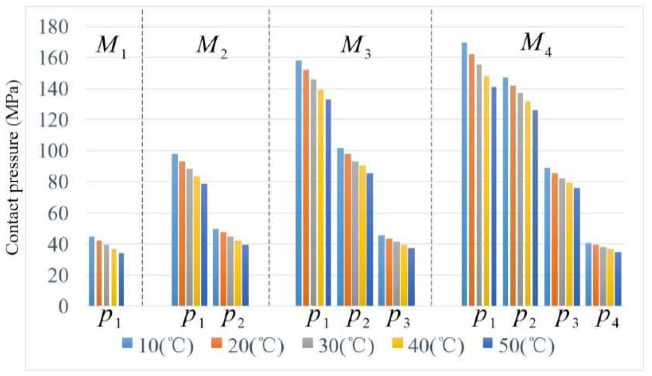
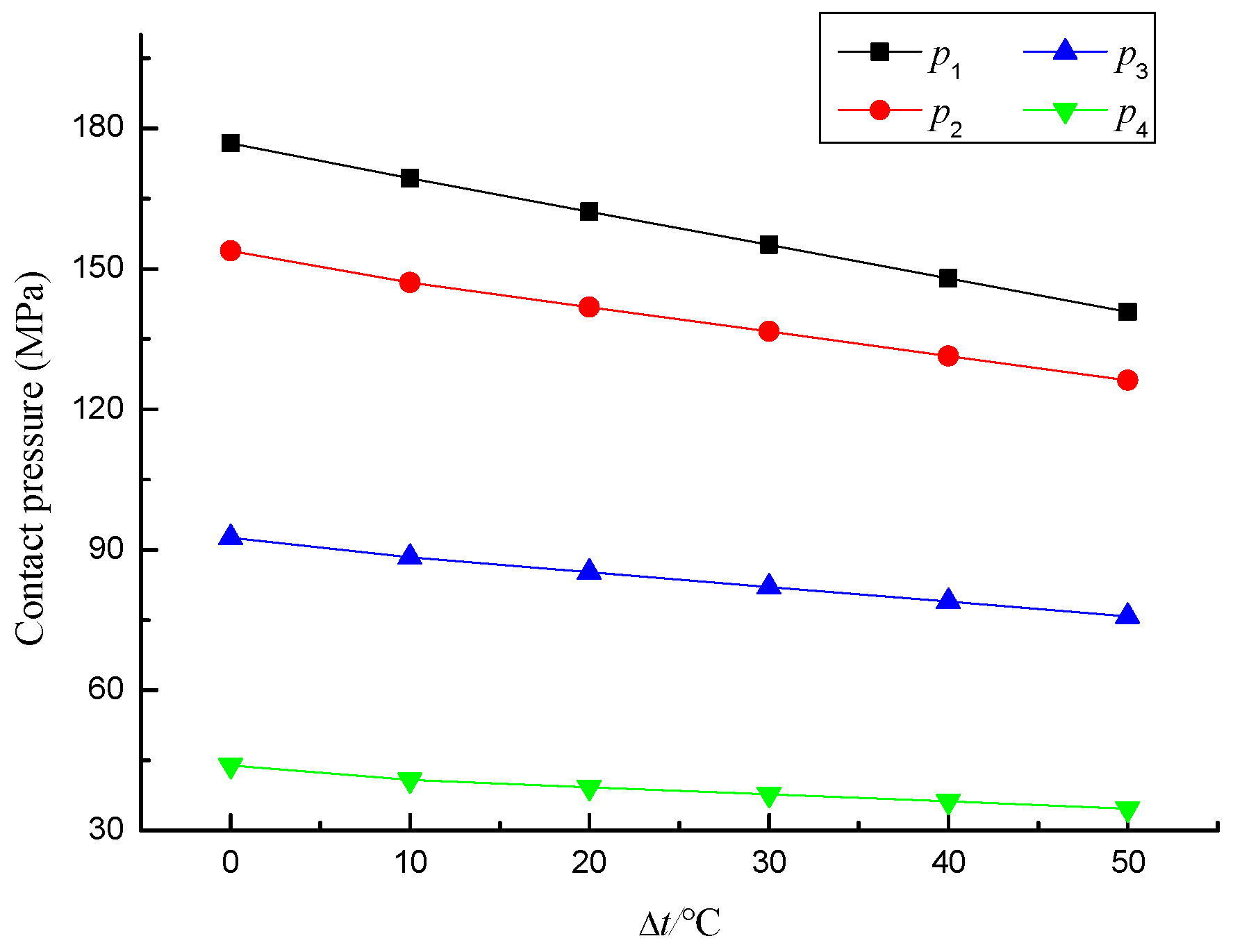
5.2. Influence of Temperature Gradient

According to the Equations (15) and (16), the contact pressure of each contact surface of multi-layer interference cylinder is influenced by temperature of inner and outer surfaces. In Figure 6, the influence of temperature gradient on the contact pressure of multi-layer cylinder is analyzed by applying the temperature on inner and outer surfaces, then the matrix model is verified by comparing the numerical solution with the analytical solution.
According to Table 3, the temperature gradient is applied between the inner and outer surfaces respectively, and the temperature gradient is gradually increased. Ultimately, the influence of the same temperature gradient on the contact pressure of multi-layer interference cylinder is simulated and analyzed.
Figure 10 is the contact pressure diagram of model M 1 , M 2 , M 3 , and M 4 under different temperature gradients. It indicates that the contact pressure of multi-layer interference cylinder decreases with increase of temperature gradient, which is consistent with the centrifugal force.
As shown in Figure 11, the contact pressures p 1 , p 2 , p 3 , and p 4 of model M 4 decreases linearly with the increase of temperature gradient, and the rate of change decreases from p 1 to p 4 in turn, which indicates that temperature gradient will reduce interference magnitude of multi-layer interference cylinder, thereby affecting the performance of torque transmission of multi-layer interference components.
In order to validate the correctness of the relationship between contact pressure and interference magnitude of any multi-layer interference cylinder under temperature gradient, the relative error between the numerical solution and the analytical solution under the temperature gradient Δ t = 10 °C is compared and analyzed. The result is shown in Table 4.
Table 4 shows the analytical solution is basically consistent with the numerical solution. The maximum relative error is only −7.69%, which is within the allowable range of design. So, the matrix model of multi-layer interference cylinder under temperature gradient is of high accuracy.

6. Conclusions

The multi-layer interference cylinder matrix model and the finite element model under centrifugal force and temperature gradient are built, the influences of both factors on the contact pressure of the multi-layer interference cylinder are analyzed, and the algorithm is validated to be suitable for actual design. The specific conclusions are as follows:
(1)
The matrix models of the relationship between contact pressure and interference magnitude of a multi-layer interference cylinder under centrifugal force and temperature gradient are deduced based on elastic mechanics and thick-wall cylinder theory.
(2)
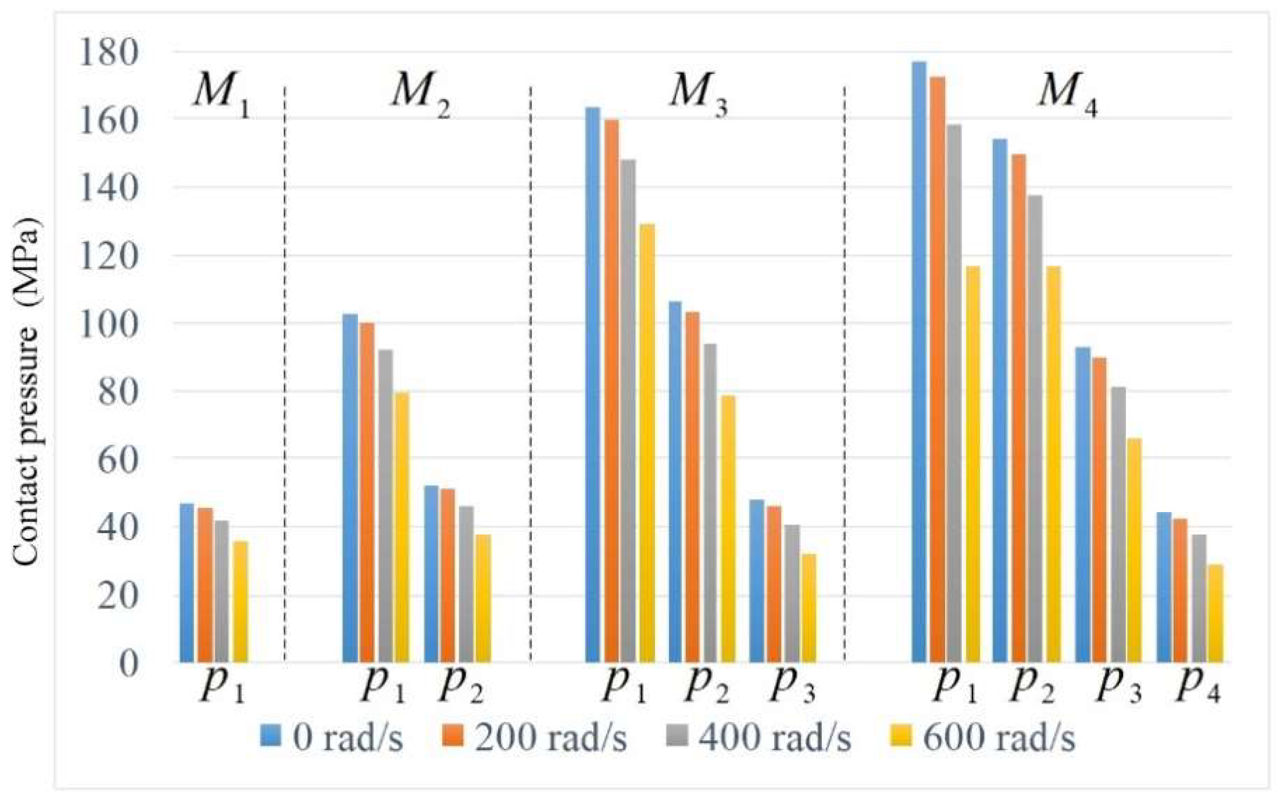
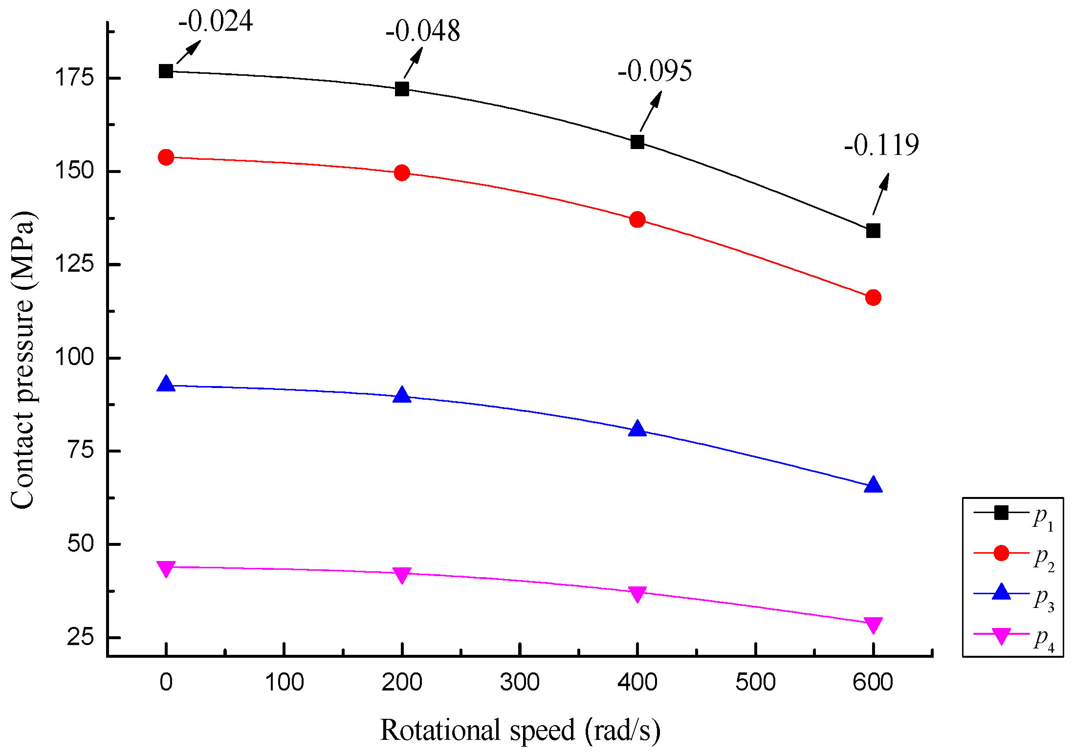
The contact pressure of multi-layer interference cylinder under centrifugal effect decreases with the increase of rotational speed, and the curve slope increases with the increase of rotational speed. The maximum radial displacement of contact surface is at the outmost layer of interference cylinder. In the same model, the radial displacement of contact surface is gradually increased from inside to outside. The interference magnitude should be compensated according to the centrifugal force during the design of multi-layer interference fit.
(3)
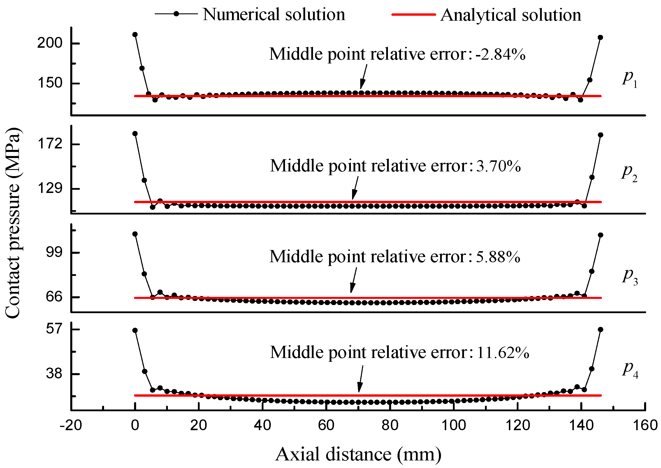
Without considering the stress concentration, the numerical solution is in good agreement with the analytical solution. Even if the maximum relative error of midpoint is 11.62%, it is kept within the allowable range of design, which shows that the matrix model of multi-layer interference fit under centrifugal force can be used for design reference.
(4)
The contact pressure of multi-layer interference cylinder decreases linearly with increase of temperature gradient. The maximum relative error of analytical solution and numerical solution under temperature gradient is −7.69%, which is in the allowable design range. It indicates that the matrix model of multi-layer interference fit under the same temperature gradient can be used for reference.

Author Contributions

Z.B. and J.W. conceived the research direction and wrote the paper; K.N. designed finite element simulation; Z.B. and K.N. analyzed the data; D.H. collected relevant information.

Acknowledgments

This work was supported by the National Science Foundation of China (no. U1610109 and 51505475), the Shanxi Provincial Natural Science Foundation of China (no. 201601D011049), the Shanxi Provincial Key Research and Development Project (no. 201603D111017), and the Provincial Special Fund for Coordinative Innovation Center of Taiyuan Heavy Machinery Equipment (1331 Project).

Conflicts of Interest

The authors declare no conflict of interest.

References

  1. Wang, J.; Ning, K.; Xu, J.; Li, Z. Reliability-based robust design of wind turbine’s shrink disk. Proc. Inst. Mech. Eng. Part C J. Mech. Eng. Sci. 2017. [Google Scholar] [CrossRef]
  2. Sogalad, I.; Ashoka, H.N.; Udupa, N.G.S. Influence of cylindricity and surface modification on load bearing ability of interference fitted assemblies. Precis. Eng. 2012, 36, 629–640. [Google Scholar] [CrossRef]
  3. Zhang, Y.; Wang, S. Analysis of contact stress and dynamic performance of conical interference fit based fit based on FEA model. J. Donghua Univ. 2014, 40, 117–121. [Google Scholar]
  4. Wang, J.; Kang, J.; Tang, L. Theoretical and experimental studies for wind turbine’s shrink disk. Proc. Inst. Mech. Eng. Part C J. Mech. Eng. Sci. 2014, 229, 325–334. [Google Scholar]
  5. Wang, J.; Kang, J.; Tao, D. The design method of multi-layer interference fit. J. Sichuan Univ. 2013, 45, 84–89. [Google Scholar]
  6. McMillan, M.D.; Booker, J.D.; Smith, D.J. Analysis of increasing torque with recurrent slip in interference-fits. Eng. Fail. Anal. 2016, 62, 58–74. [Google Scholar] [CrossRef]
  7. Boutoutaou, H.; Bouaziz, M.; Fontaine, J.F. Modeling of interference fits taking form defects of the surfaces in contact into account. Mater. Des. 2011, 32, 3692–3701. [Google Scholar] [CrossRef]
  8. Boutoutaou, H.; Bouaziz, M.; Fontaine, J.F. Modelling of interference fits with taking into account surfaces roughness with homogenization technique. Int. J. Mech. Sci. 2013, 69, 21–31. [Google Scholar] [CrossRef]
  9. Li, J.; Zhang, K.; Li, Y.; Liu, P.; Xia, J. Influence of interference-fit size on bearing fatigue response of single-lap carbon fiber reinforced polymer/Ti alloy bolted joints. Tribol. Int. 2016, 93, 151–162. [Google Scholar] [CrossRef]
  10. Li, J.; Li, Y.; Zhang, K.; Liu, P.; Zhou, P. Interface damage behaviour during interference-fit bolt installation process for CFRP/Ti alloy joining structure. Fatigue Fract. Eng. Mater. Struct. 2015, 38, 1359–1371. [Google Scholar] [CrossRef]
  11. Kurvinen, E.; Sopanen, J.; Mikkola, A. Ball bearing model performance on various sized rotors with and without centrifugal and gyroscopic forces. Mech. Mach. Theory 2015, 90, 240–260. [Google Scholar] [CrossRef]
  12. Guo, T.; Ma, X.; Gu, Y.; Chen, J. Effect of the Interference Fit Amount Impact on the Dynamic Characteristics of Spindle. J. Beijing Univ. Technol. 2016, 42, 51–59. [Google Scholar]
  13. Ding, H.; Xiao, L.; Zhang, H. Interference Fit Calculation and Stress Analysis for Rotor Sleeve of High-speed Permanent Magnet Electric Machine. Mech. Des. Res. 2011, 27, 95–98. [Google Scholar]
  14. Zhou, H.; Wang, Z.; Xie, Y. Precision Analysis of Interference Fits for Drive Shaft based on FEA. Mech. Drive 2010, 34, 60–62. [Google Scholar]
  15. Qiu, J.; Zhou, M. Analytical Solution for Interference Fit for Multi-Layer Thick-Walled Cylinders and the Application in Crankshaft Bearing Design. Appl. Sci. 2016, 6, 167. [Google Scholar] [CrossRef]
  16. Wang, J.; Ning, K.; Tang, L.; Malekian, R.; Liang, Y.; Li, Z. Modeling and Finite Element Analysis of Load-Carrying Performance of a Wind Turbine Considering the Influence of Assembly Factors. Appl. Sci. 2017, 7, 298. [Google Scholar] [CrossRef]
  17. Xu, J.; Wang, J.; Ning, K.; Li, P. Study on contact pressure algorithm of N layer interference fit. J. Eng. Des. 2017, 24, 83–88. [Google Scholar]
  18. Xu, Z. Elastic Mechanics; Higher Education Press: Beijing, China, 2006; pp. 54–57. [Google Scholar]
  19. Luo, Z.; Fei, Y. Research on deformation of hollowed parts based on heat and stress state. J. Harbin Inst. Technol. 2006, 38, 1586–1589. [Google Scholar]
  20. Croccolo, D.; Agostinis, M.D. Analytical solution of stress and strain distributions in press fitted orthotropic cylinders. Int. J. Mech. Sci. 2013, 71, 21–29. [Google Scholar] [CrossRef]
  21. Croccolo, D.; Vincenzi, N. A generalized theory for shaft–hub couplings. ARCHIVE Proceedings of the Inst. Mech. Eng. Part C J. Mech. Eng. Sci. 2009, 223, 2231–2239. [Google Scholar] [CrossRef]
  22. Urade, S.D.; Bhope, D.V.; Khamankar, S.D. Stress Analysis of Multilayer Pressure Vessel. Int. J. Eng. Tech. Res. 2014, 2. [Google Scholar] [CrossRef]
Figure 1. Low speed coupling of wind turbine.
Applsci 08 00726 g001
Figure 2. The force diagram of interference cylinder.
Applsci 08 00726 g002
Figure 3. A schematic diagram of the centrifugal force of a micro unit.
Applsci 08 00726 g003
Figure 4. Multi-layer interference cylinder model.
Applsci 08 00726 g004
Figure 5. Three-dimensional model of multi-layer interference cylinder, (a) Boundary condition diagram; (b) Mesh partition diagram.
Applsci 08 00726 g005
Figure 6. The temperature gradient of M 4 .
Applsci 08 00726 g006
Figure 7. Contact pressure of each model under the centrifugal force.
Applsci 08 00726 g007
Figure 8. Contact pressure of M 4 at different rotational speed.
Applsci 08 00726 g008
Figure 9. Comparison between numerical solution and analytical solution.
Applsci 08 00726 g009
Figure 10. Contact pressure of each model under the temperature gradient.
Applsci 08 00726 g010
Figure 11. Relationship between contact pressure and the same temperature gradient.
Applsci 08 00726 g011
Table 1. Model parameters.
Cylinder No C 1 C 2 C 3 C 4 C 5
Internal diameter (mm)100200300400500
External diameter (mm)200300400500600
Height (mm)150
Elastic modulus206 GPa
Poisson ratio0.3
Density7800 kg/m3
Coefficient of linear expansion1.1 × 10−5
Table 2. The slope of p 1 with the increase of speed.
Comparison ParametersNumerical Value
Rotational Speed (rad/s)0200400600
Contact pressure (MPa)176172158134
Slope−0.024−0.048−0.095−0.119
Table 3. Temperature gradient parameters of model.
Inner Surface of C i /Outer Surface of C i Temperature of Inner and Outer Surfaces
t / t + Δ t
Δ T (°C)01020304050
Table 4. The result of analytic solution and numerical solution.
Contact Pressure (MPa) p 1 p 2 p 3 p 4
Analytical solution169.374147.05988.40840.801
Numerical solution172.561146.76895.78341.929
Relative error−1.85%0.198%−7.69%−2.69%

