Article

Experimental Study of Ground Subsidence Mechanism Caused by Sewer Pipe Cracks

Department of Civil and Environmental Engineering, Korea Advanced Institute Science and Technology (KAIST), Daejeon 34141, Korea
*
Author to whom correspondence should be addressed.
Appl. Sci. 2018, 8(5), 679; https://doi.org/10.3390/app8050679
Submission received: 14 March 2018 / Revised: 14 April 2018 / Accepted: 19 April 2018 / Published: 26 April 2018

Abstract

:
Simultaneous leakage of soil particles and groundwater into underground vacant spaces caused by sewer pipe defects and cracks can cause underground cavities and even ground collapse on the surface. Numerical studies of this problem are limited, and the mechanism of ground subsidence caused by leakage of soil and groundwater into construction sites has yet to be verified. In this study, the factors affecting the mechanism of ground subsidence are verified via physical modelling of a sewer pipe defect. Through visual inspection and particle image velocimetry analysis, it has been found that the groundwater flow direction, hydraulic gradient around the leakage point, and strength of the ground to support itself are the main factors that dominate the mechanism of ground subsidence. These factors can affect ground deformation and cavity expansion direction, ground subsidence development and collapse speed, and occurrence of sudden ground collapse, respectively. It was also found that pore pressure fluctuates when cavity cavern collapse and cavity expansion occur.

1. Introduction

As an urban area grows, buried pipeline systems are required to supply water and provide drainage for the city. These pipeline systems cannot avoid ageing, and thus, cracks can occur in the sewage pipes. Kuwano et al. [1] showed that pipes that are more than 25 years old have a significant increase in defects. For the efficient use of urban space, subway tunnels, basements of high-rise buildings, and water supply sewer pipes are constructed and buried underground. Due to improper construction management, insufficient management of these facilities, or exceedance of the lifetime, these underground structures can disturb adjacent ground. When this disturbance initiates and propagates to the surface, the surface may settle downwards or suddenly sink due to internal erosion, as shown in Figure 1 [2,3]. Sinkhole incidents affect infrastructure and property, and in some cases, can endanger lives. Several techniques have been employed to prevent such incidents, including underground cavity detection using ground penetrating radar (GPR). Although GPR is a fast and non-destructive method, difficulties remain in detecting smaller cavities [4,5]. Indiketiya et al. [6] conducted tests simulating cyclic sewer pipe defects with particle image velocimetry (PIV) tracking and found that void formations occurred above pipe openings, followed by a settlement of the soil surface.
There are many causes of ground subsidence. In Seoul, sewer and water supply pipeline defects, groundwater level drawdown, and excavation activity are the main causes of ground subsidence. Around 85% of all ground subsidence cases are caused by sewer pipe defects, while 14% are caused by excavation activities during construction (Seoul Metropolitan Government [7]). For example, soil particle loss along with groundwater leakage through a defect in an excavation wall triggered a sudden ground sinking into which two pedestrians fell near a construction site at Yongsan Station, Seoul, Korea [8]. In addition, a huge ground sinking around a tunnel construction site in Fukuoka, Japan was caused by groundwater leakage into the tunnel [9,10,11]. Although many cases are related to groundwater-related problems, the mechanism of ground subsidence caused by groundwater is not yet clearly understood.
Currently, ground subsidence is not well studied, and as previously mentioned, it can have many causes and factors. The present study focuses specifically on ground subsidence induced by sewer pipe leakage. Tests simulated cracks occurring in sewer pipes and the succession of flooding and drainage during rainy seasons.
A small-scale model test method was used to understand the different mechanisms of ground subsidence according to different groundwater flow modes. Vertical drainage tests were performed to simulate groundwater leakage from sewer pipe cracks, and water supply and drainage tests were performed to simulate the various possible underground soil responses. Various methods of observation were used to monitor the mechanisms of specimen failure. A camera was used to record the tests in their entirety. Pore pressure and suction measurements were used to monitor variations within the specimen that could not directly be observed. Settlement was measured through laser sensors, as well as collapse time. Test results were then discussed and summarized to estimate the effect of groundwater flow mode on the ground subsidence mechanism.

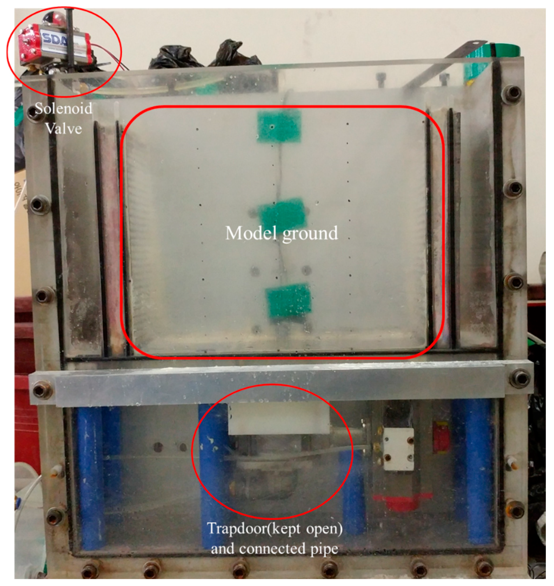
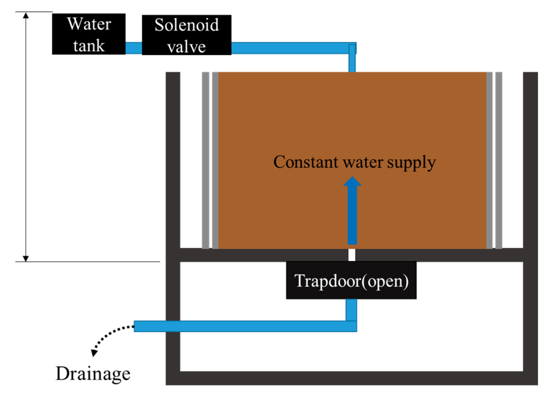
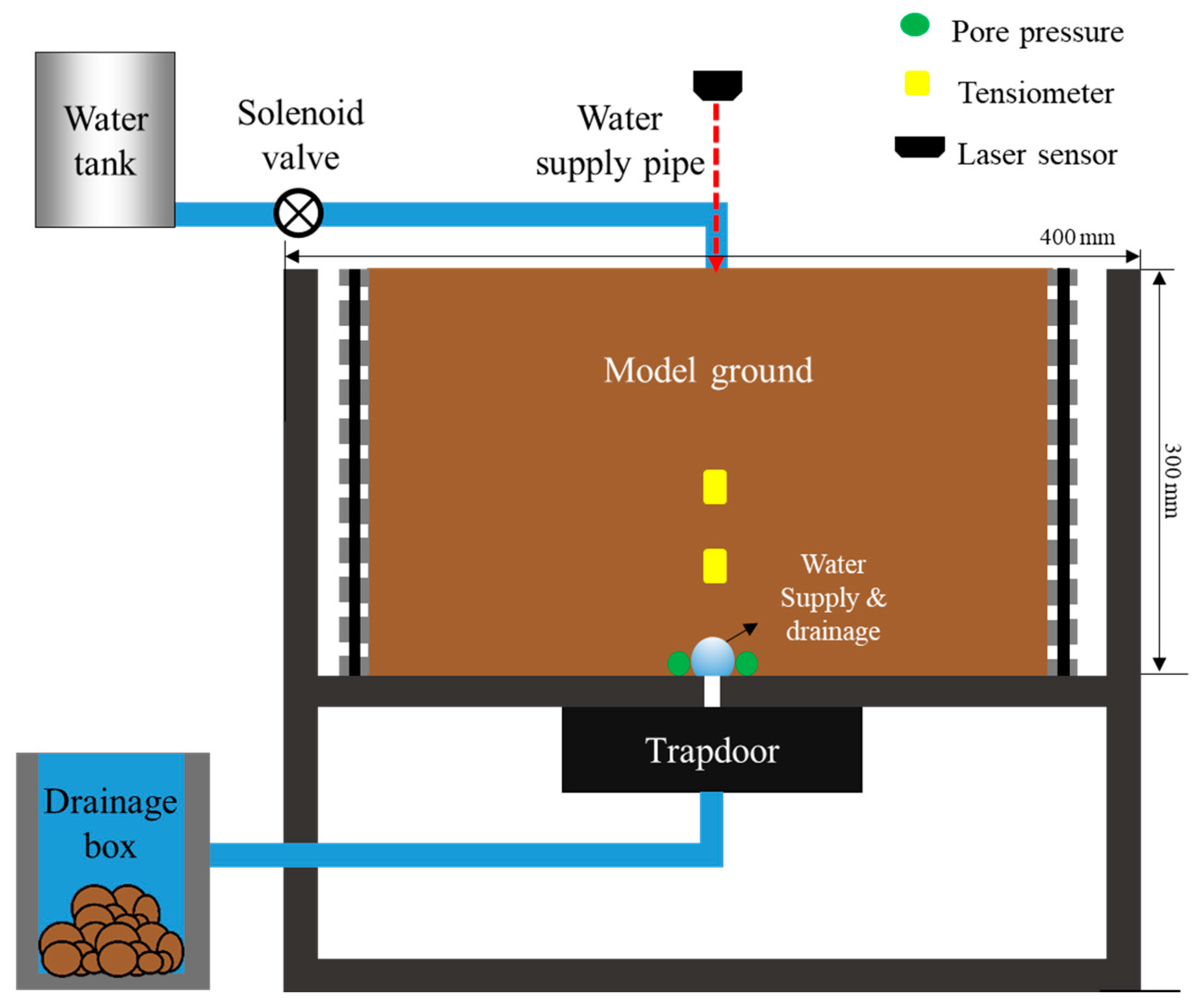
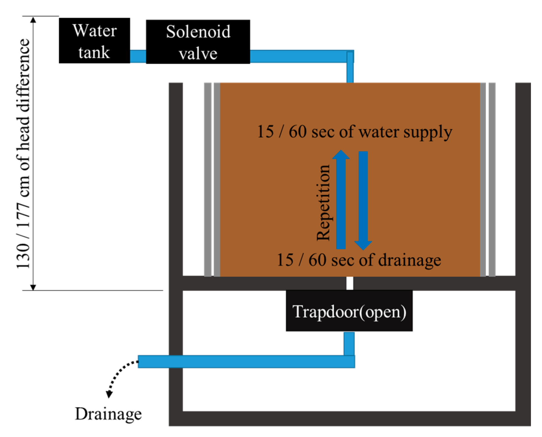
2. Materials and Methods

This aim of this research is to investigate the effect of repetitive cycles of water leakage and drainage within sewer pipes on ground subsidence mechanisms. The model box used in the tests is shown in Figure 2. The model box can contain a model size of 400 mm × 300 mm × 140 mm. Water was supplied from an outside water tank, in which the water level remained constant to ensure a constant pressure head for the supplied water. A water supply pipe from the water tank was connected to a solenoid valve that precisely controlled the water supply via computer. This water supply pipe was then buried through the soil along the back wall of the model box through to the bottom of the model ground to supply the water right above the opening located at the bottom center of the model ground. A 5-mm-wide opening was located at the bottom center of the model ground, and a trapdoor was located further below to simulate a crack in the pipe. The water supply pipe was connected to the trapdoor to collect and transport leaked outflow. This test setup is shown in Figure 3.
Silica sand was used for this study and its properties are summarized in Table 1. The soil was compacted at an optimum moisture content of 18%, and the relative density was 65%. The maximum dry density from the compaction curve was 15.4 kN/m3, and the degree of compaction stipulated in the Korean domestic code is 95% for overburden soil. This corresponds to 65% of the relative density of the test soil.
Surface settlement was measured through a laser sensor placed over the soil specimen. Pore pressure at the opening was measured, as was suction pressure above the opening. The locations of the sensors are shown in Figure 3. A camera was used to record all tests, and physical measurements were correlated with visual observations.
Five test cases with two different pressure heads and three different water supply cycles were performed. Pressure heads of 130 cm and 177 cm were chosen to investigate water head influence. For the water supply test, there were three different methods. First, a continuous water supply was applied until the propagation of the cavity to the surface. Second, a succession of supply/drainage cycles was applied to the specimen until collapse. Each supply and each drainage cycle lasted 15 s, after which the same succession of supply and drainage cycles was applied for 60 s. Figure 4 and Figure 5 show a schematic of the water supply modes. The purpose of these experiments was to investigate ground subsidence induced by sewer pipe leakage. Continuous water supply was used to simulate the occurrence of a crack in a sewer pipe, while cyclic water supply simulated the cycles of flooding and drainage during rainy periods.

3. Test Results and Discussion

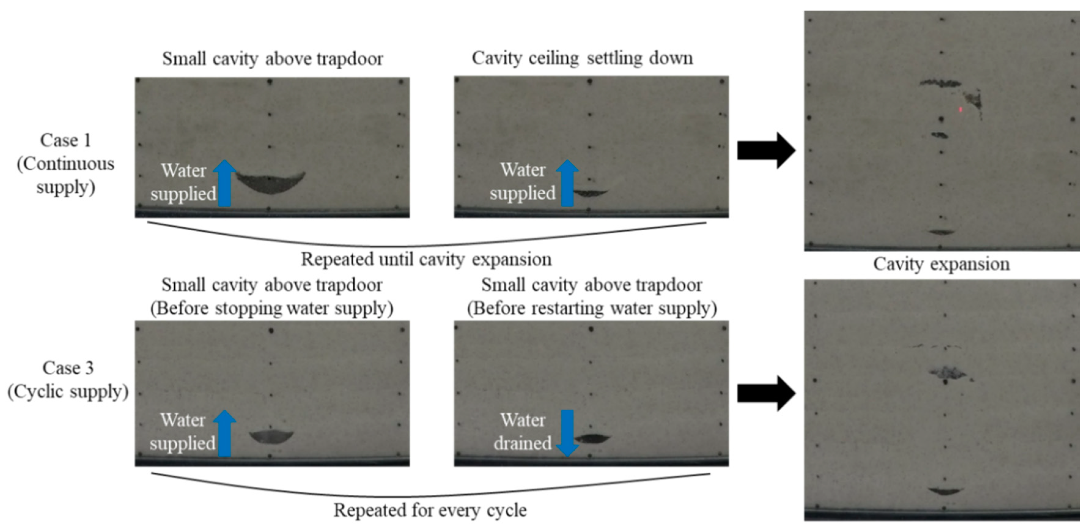
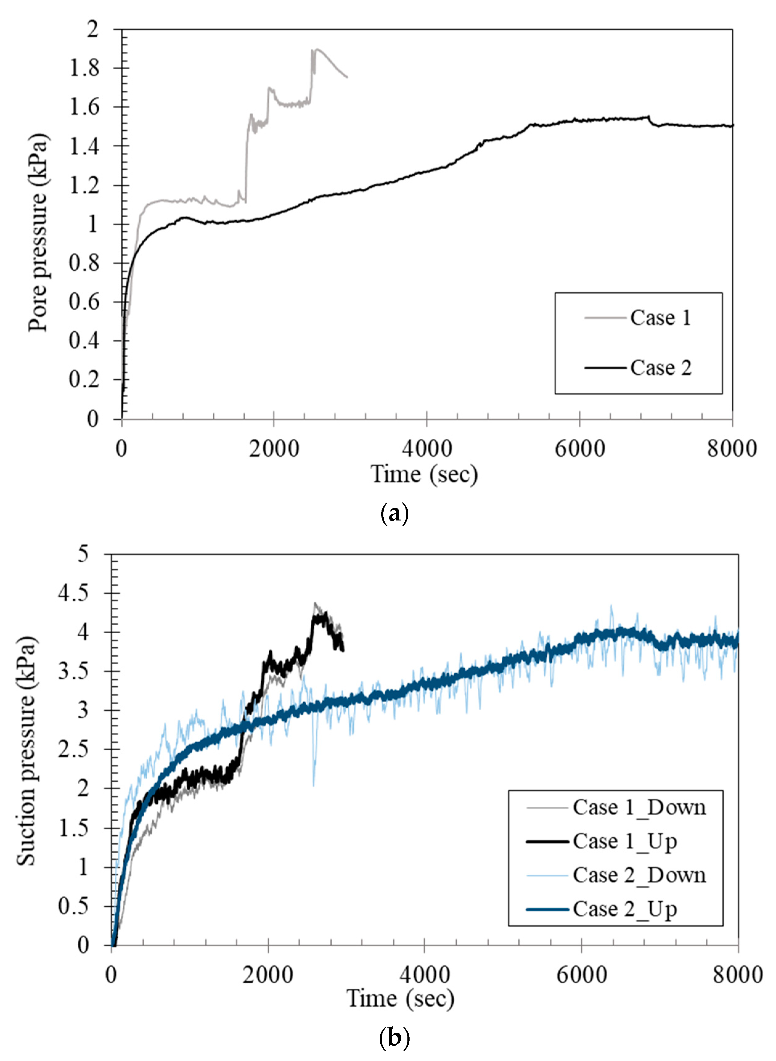
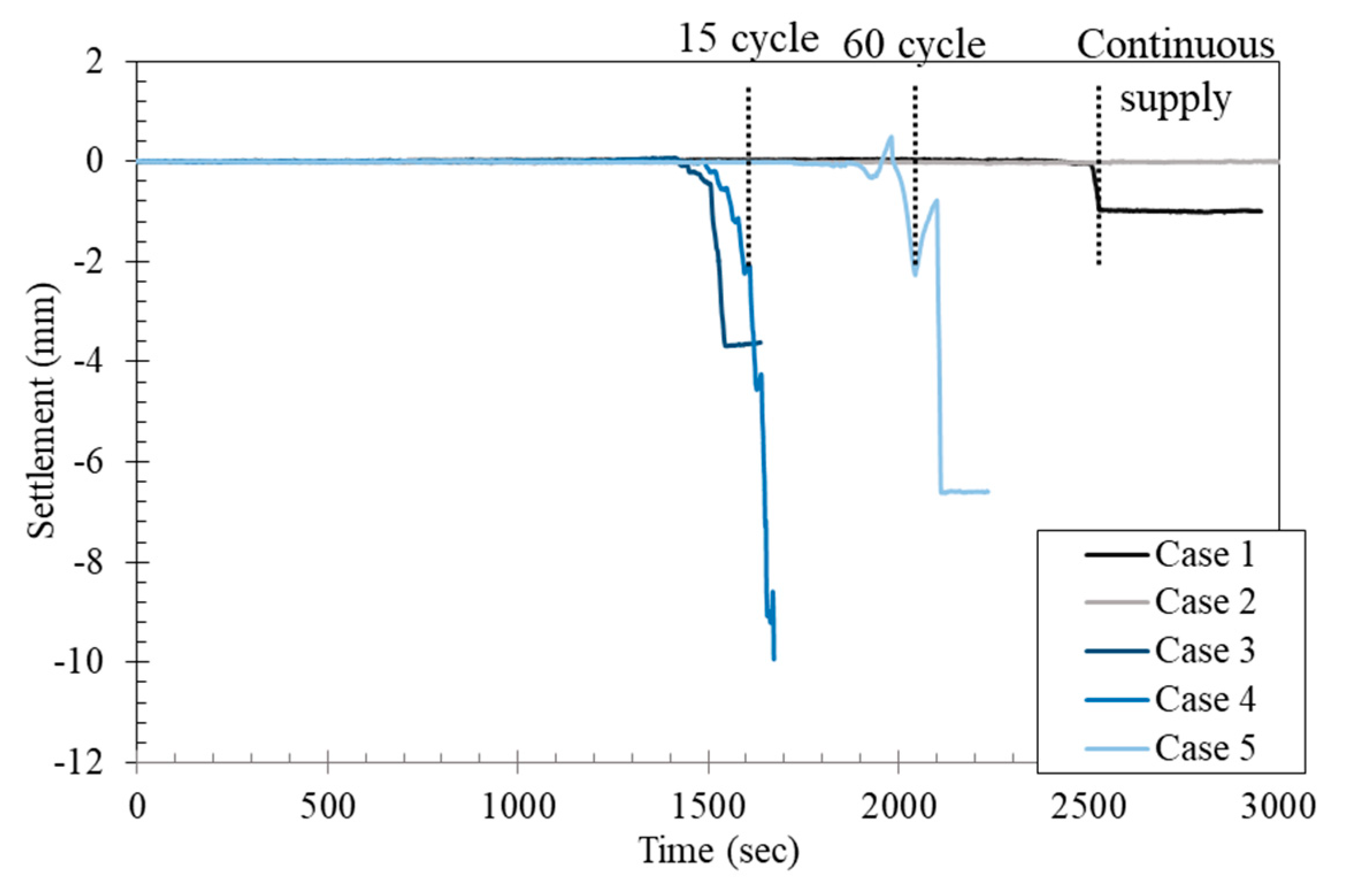
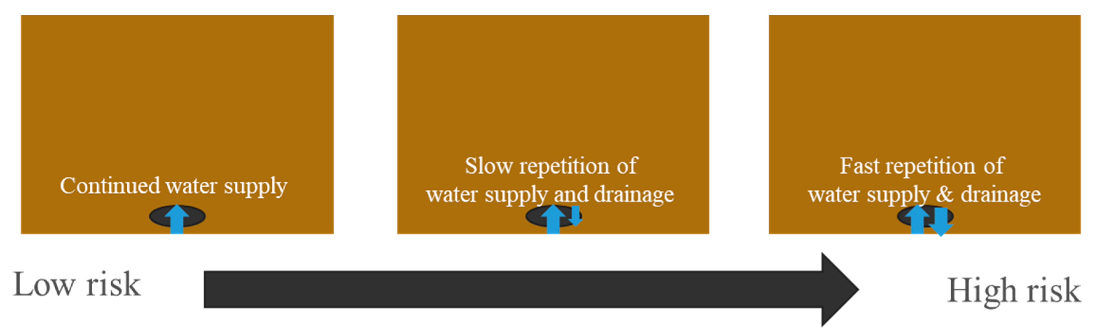
3.1. Continuous Water Supply vs. Cyclic Water Supply

In Table 2, test cases are summarized. Cavity formation cycles for the continuous water supply cases and cyclic water supply cases both had similar and different behaviors. For both water supply methods, cavity formation and closing was observed. The cavities formed and closed directly above the water opening at the early stages of the experiments. This process of cavity formation and closing continued during the experiments, increasing in size. As the cavity size increased, it led to a collapse of its ceiling and the formation of a cavity above the previous one in the middle of the soil specimen (Figure 6). This mechanism was pursued until the collapse of the upper layer of the soil specimen. The difference between the water supplies triggered the cavity contraction. For the continuous water supply case, the cavity expansion and contraction cycle continued with a continuous water supply from the bottom, and did not follow any particular trend. Meanwhile, for the cyclic water supply case, cavity contraction occurred when the water was drained, while the cavity expanded when the water was supplied. Thus, each cycle corresponded to a cavity formation and contraction.
For the continuous water supply cases, the increase in pore pressure was not uniform (Figure 7a). Pikes were observed and corresponded to cavity formation and collapse throughout the test until the experiment was stopped due to the failure of the soil. The same trend was observed with the suction measurements, as shown in Figure 7b. This indicates that the ground over the initial cavity ceiling was gradually saturated, leading to a decrease in effective shear stress, which was related to a decrease in the shear strength of the cavity ceiling. With this, the saturated area over the cavity ceiling collapsed after repeated initial cavity expansion and contraction. Although the water head applied to Case 2 was higher than the water head applied to Case 1, no collapse was observed for Case 2. The soil specimen in Case 1 collapsed, while only a small settlement was observed for Case 2.
During the cyclic water supply cases, the cavity expansion and contraction process followed the water supply and drainage cycles. Whenever the water was supplied, the pore pressure on the opening increased and the cavity expanded, whereas cavity contraction and pore pressure decreased following drainage (Figure 8a). This cycle is well expressed in Figure 8b, where Part A in Figure 8a is enlarged. Part A corresponds to the early cycles and shows the increase and decrease of the pore pressure values following the supply and drainage cycles. In Figure 8c,d, the cavity contraction can be seen with the cessation of the water supply and the drainage of leaked water. After the water was supplied again in the 18th cycle, the cavity expanded again, and when the supply of water ended and pore pressure decreased, the cavity contracted again. Part B of Figure 9a corresponding to the last cycles is enlarged in Figure 9b, and represents the cavity propagation upward, preceded by the sudden increase in the groundwater level, as represented by the sudden increase in pore pressure. The higher values of pore pressure correspond to larger cavity size. During this stage, the cavity expansion and contraction cycle was repeated on a larger scale and higher in the soil specimen. As shown in Figure 9c,d, when the water supply stopped and leaked water was drained, the ground over the cavity ceiling settled downward and additional cracks occurred over the cavity, which indicated that the cavity contracted with drainage and pore pressure dropdown.
The expansion and contraction cycle was found in Case 5, as shown in Figure 10. Significant ground surface settlement occurred, and this can be seen when comparing Figure 10b, which represents the pore pressure measurements, and Figure 10c,d, which show cavity apparition and contraction following the cycles of supply and drainage. These cycles were repeated with an increase in cavity size and migration higher up in the soil specimen until final collapse. From Figure 11a displaying case 5, the last cycles circled in B area will be discussed. Figure 11b shows the last cycles before collapse, as well as the high amplitude of pore pressure values that correspond to water supply and drainage. In Figure 11c, Image 5 was taken during a period of water supply, and corresponds to an increase in pore pressure. It shows the formation of a cavity larger in size than observed during the early stages of the test. In Figure 11d, Image 6 was taken during the drainage period, and shows the contraction of the cavity and the collapse of its ceiling. This collapse was due to the loosening of the soil after each drainage.
In addition, the suction pressure shows that after initial cavity formation around the opening in the first stages of the test and in each repeated water supply test, the maximum suction value was higher in the tensiometer closer to the opening (down) than that it was in the tensiometer farther from the opening (up), as shown in Figure 12. This indicates that during the cavity expansion and contraction, the cavity ceiling was saturated, as indicated by the higher suction in the tensiometer closer to the cavity. This local increase in saturation may lead to a local decrease in soil cohesion, and the cavity expansion led to the loosening of soil and settlement over the cavity ceiling.

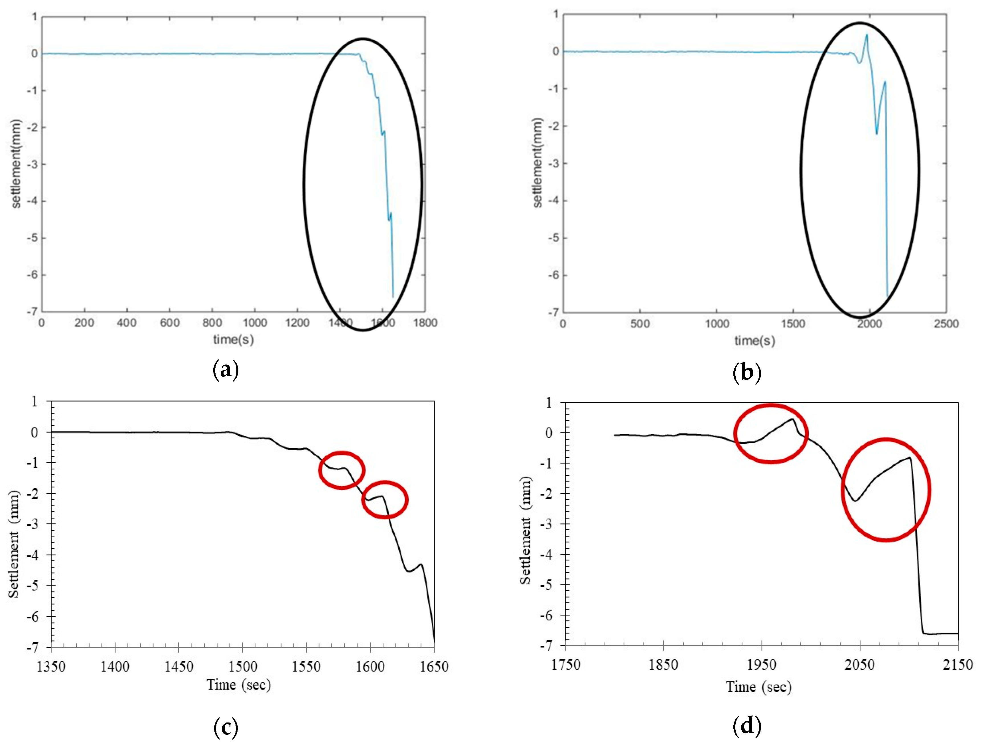
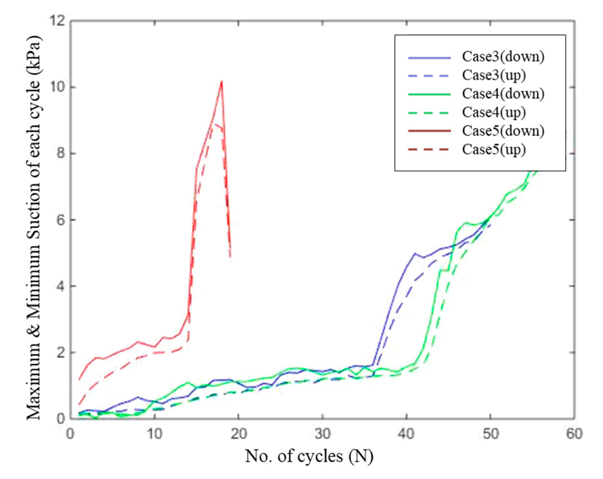
3.2. Ground Subsidence Process Speed According to the Water Supply Mode

The collapse time shown in Table 3 and Figure 13 does not vary with the water supply head, indicating the independence of the water supply head on the speed of the collapse. As observed, the cyclic tests had a faster collapse time than the continuous tests. Among cyclic tests, the shorter cycles collapsed faster than the longer cycles. This indicates, that alternating supply and drainage was more harmful to soil structure than a constant exposure to water, as it created uneven saturation in the soil. Short cycles weakened a small area around the water supply opening, while longer cycles saturated larger areas, reducing the unbalanced saturation in the soil. On the other hand, the continuous test saturated the whole soil specimen.

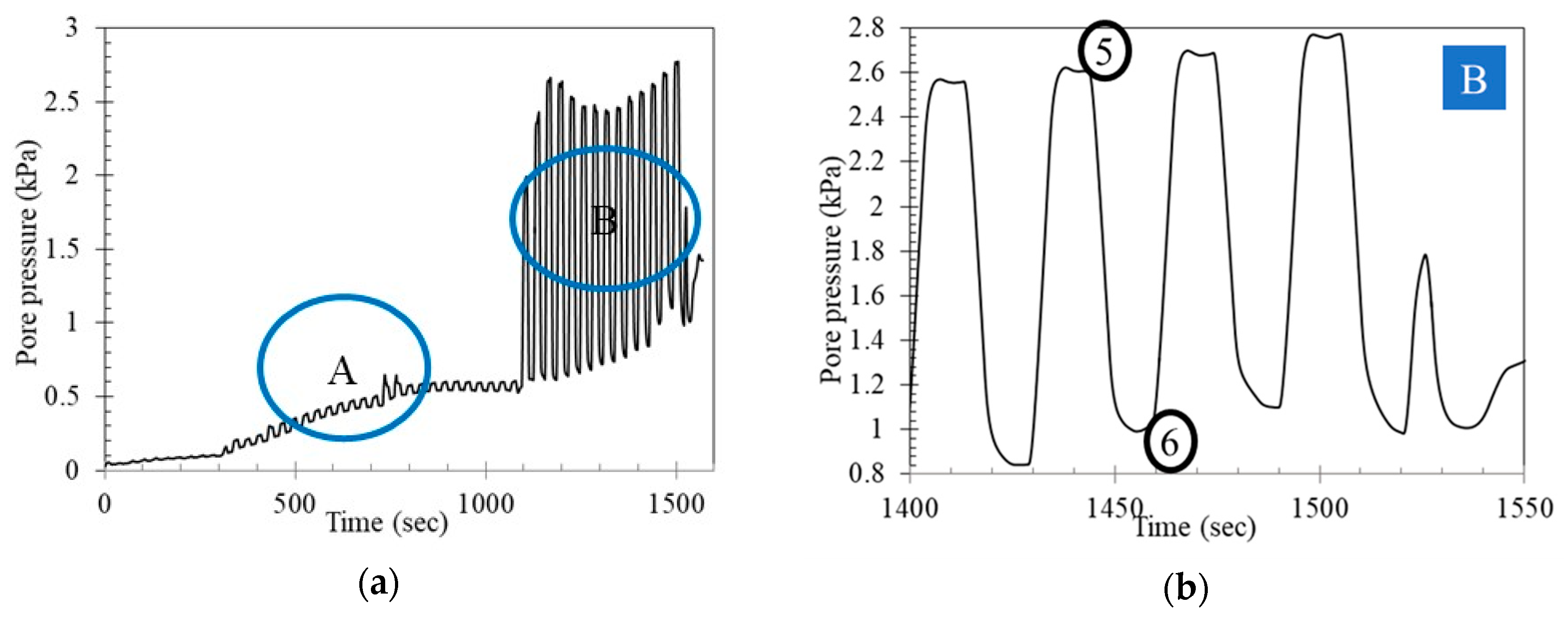
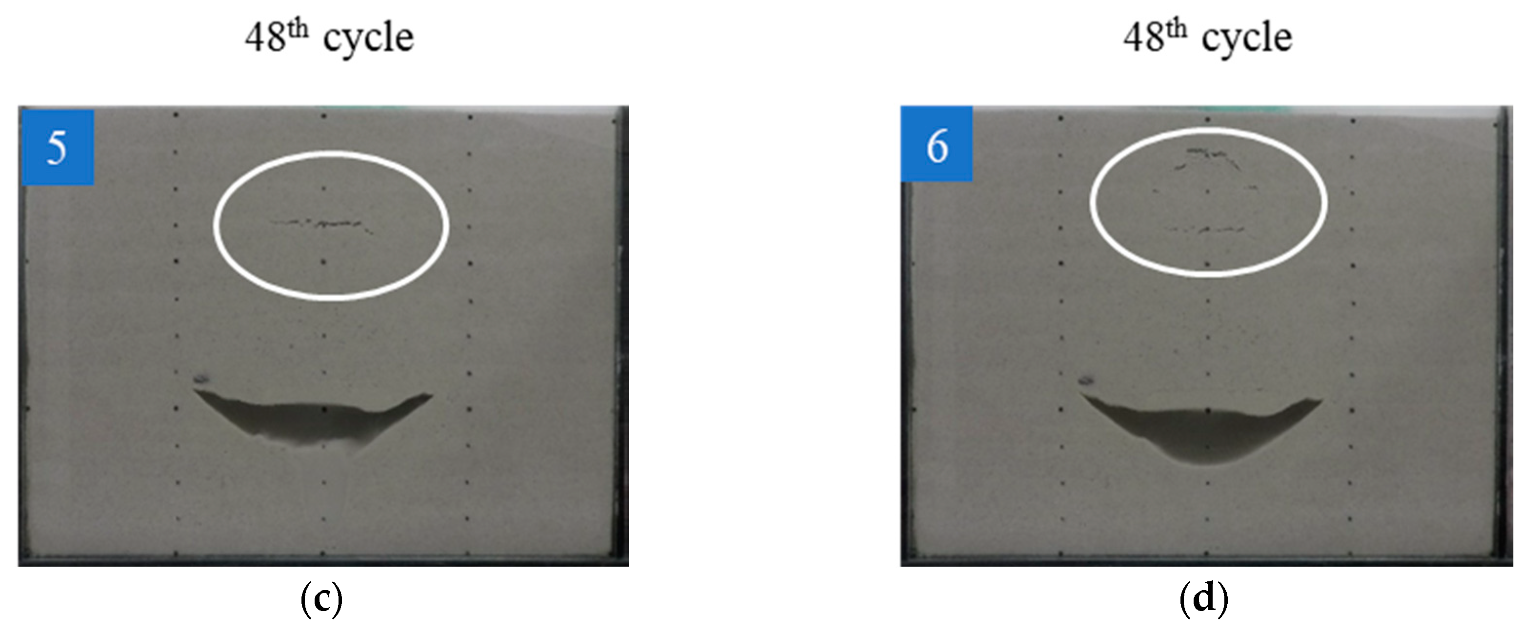
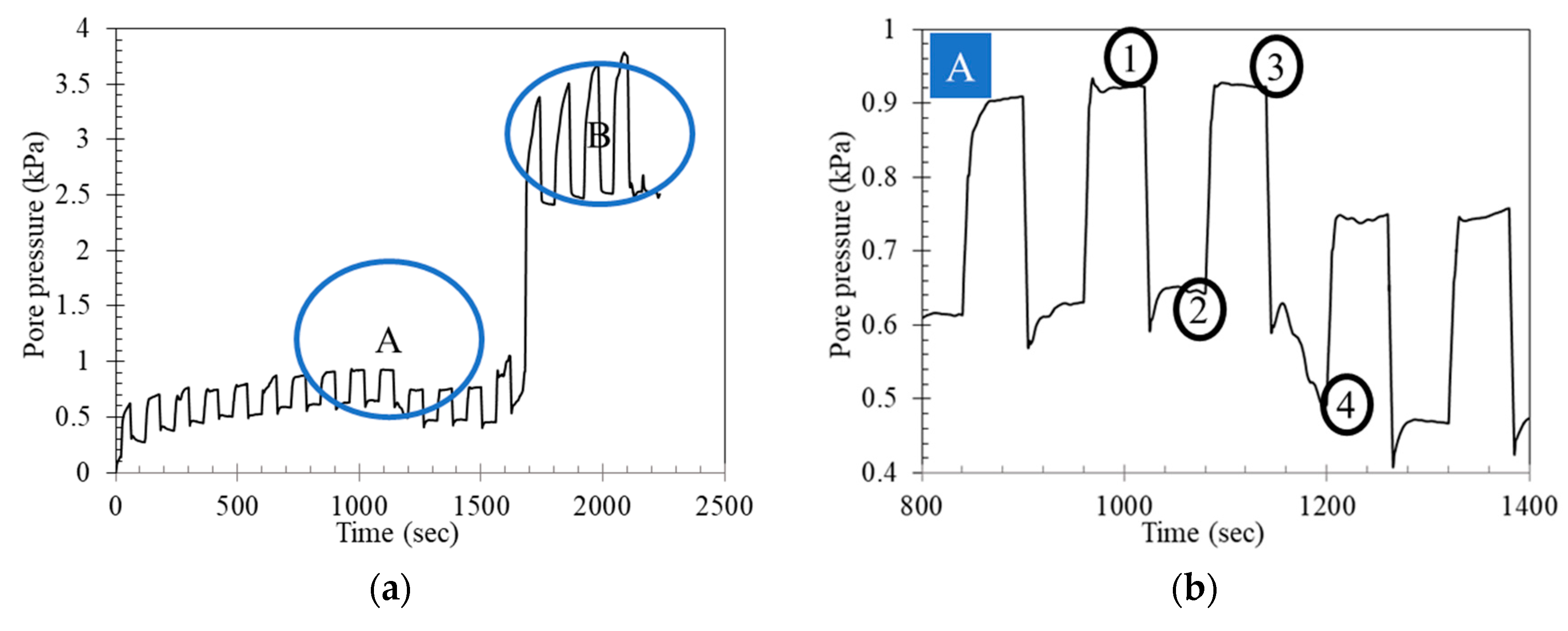
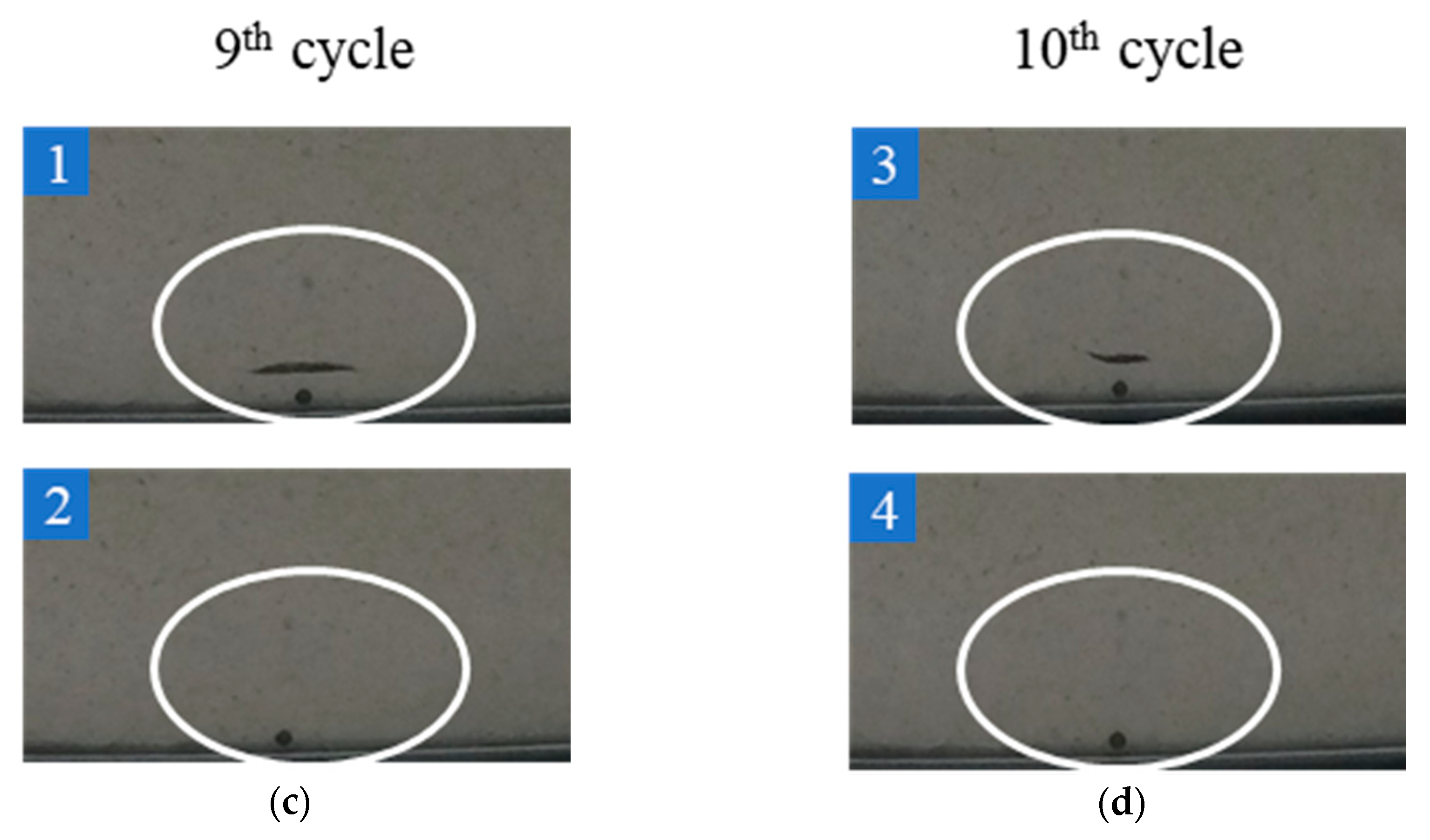
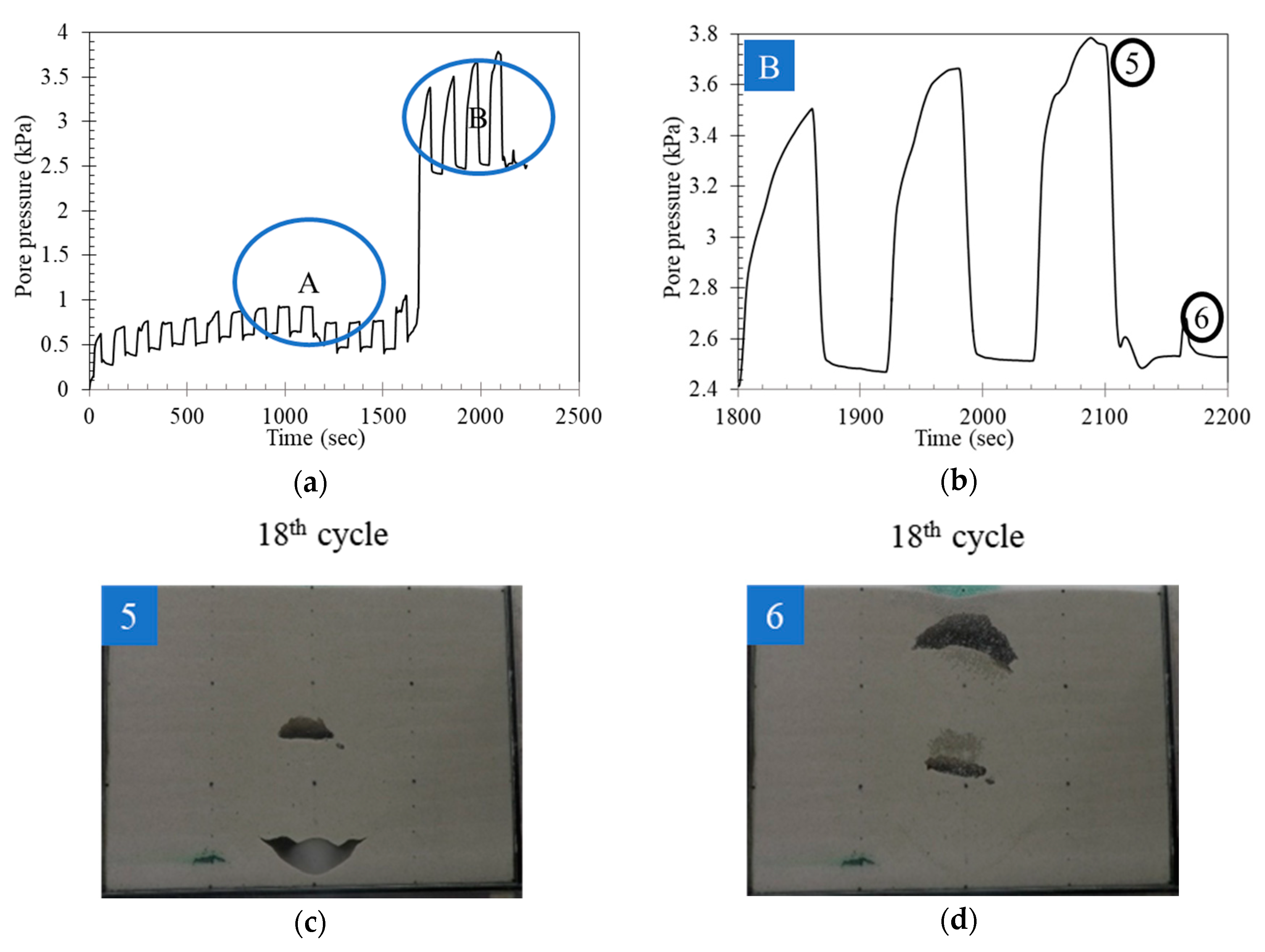
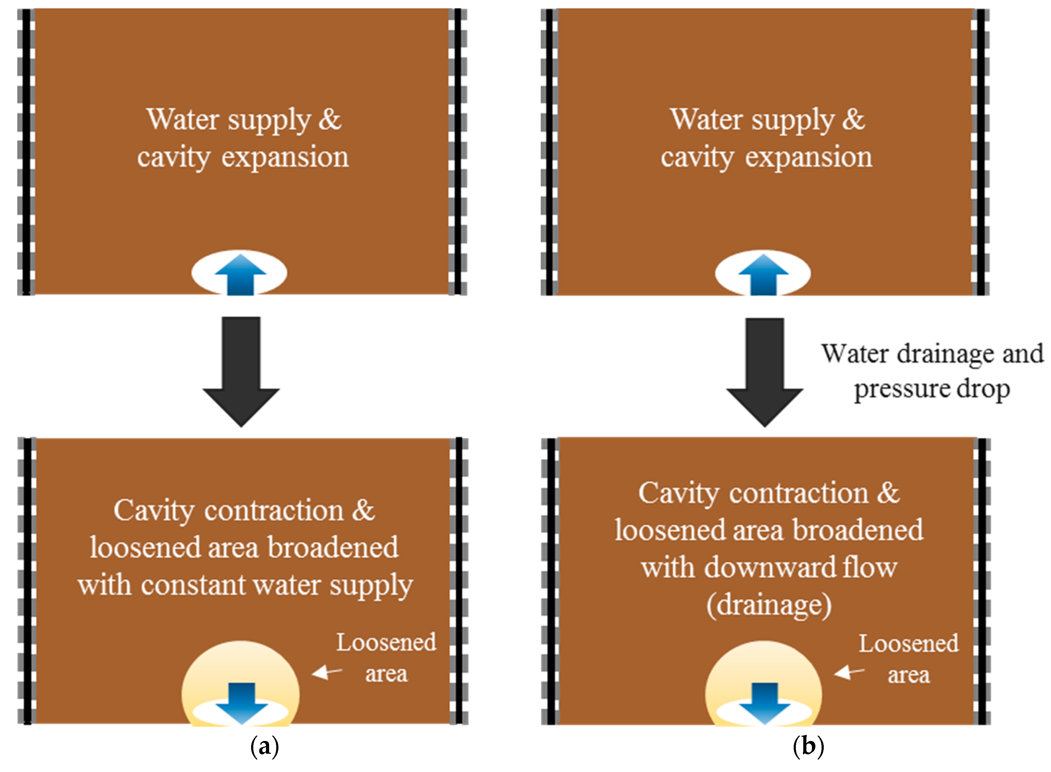
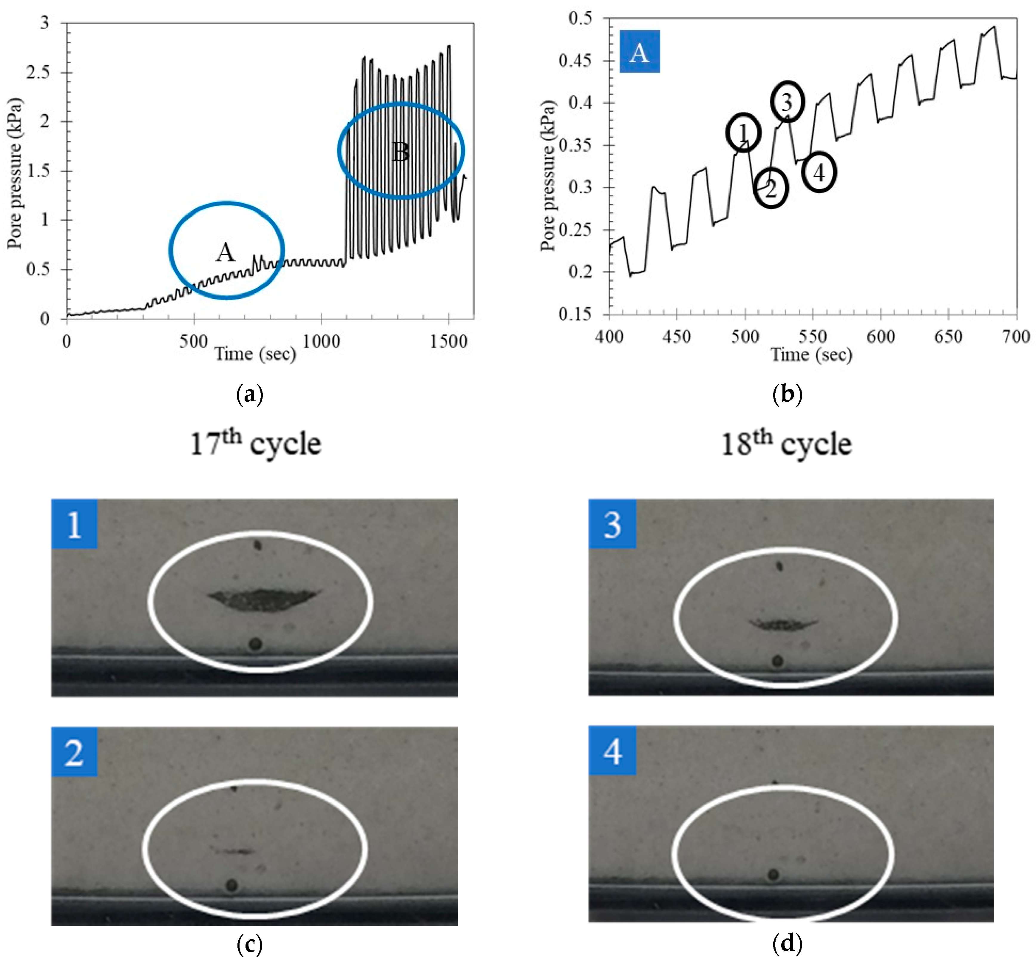
3.3. Effect of Buoyancy on the Cavity Expansion and Contraction

The water supply for each case applied buoyant force on the ceiling of the cavity. This was indicated by the settlement measurements. Figure 13 shows the surface settlement of Case 4 and Case 5. The black circled areas in Figure 14a,b are enlarged in Figure 14c,d, respectively, and indicate the last cycles before the total collapse of the soil specimens. As shown in the red circle in Figure 14c,d, an upwards settling was observed during each water supply, followed by an important settlement. This indicates that all the soil above the opening was affected by the water supply, and was floating, thus indicating a phenomenon of buoyancy during the cavity expansion stage.

3.4. Summarized Ground Subsidence Mechanism and Influence Factors

As observed from the experiments, the main influencing factors on the mechanism of ground subsidence were the water supply mode and its periodicity. The effect of the water supply mode on the cavity expansion and contraction cycle was different for continuous water supply and cyclic water supply. When leakage occurred continuously from the pipeline, the cavity formed around the crack, gradually growing by the ground deformation. Water leakage occurred without cease in this case, and ground loosening due to drainage of leaked water did not occur with a particular trend, as shown in Figure 15a. Therefore, the speed of the ground subsidence process was slower than that of the cyclic leakage from the pipe. On the other hand, when the leakage and drainage cycle occurred from the pipeline, the cavity formed or expanded during the water leakage, contracting due to downward seepage during the drainage stage of each cycle, as shown in the Figure 15b. Because of the existence of the drainage stage in the cyclic water leakage, the ground loosening occurred faster in the cyclic leakage case than in the continuous leakage case. In short, the existence of downward seepage and buoyancy according to the water supply mode had an influence on the ground subsidence mechanism.
The risk level according to the water supply mode is summarized in Figure 16. The risk level was assumed according to the collapse time. Continuous leakage is less risky than the repeated leakage, as the collapse happens more slowly than with cyclic leakage. Additionally, provided that the water leakage and drainage cycle occurs without cease after each cycle as in the test cases, the faster the speed of the repetition of the cycle (or the water leakage and drainage time of each cycle), the riskier the leakage of the pipeline becomes, as shown in the collapse times in Table 3. Each cycle of supply/drainage corresponds to a cavity formation/contraction. However, the cycle of the water leakage and drainage required for the collapse increased as the water supply and drainage time decreased.
The ground subsidence process in the case of the pipeline leakage is summarized in Figure 17. After leakage from the pipeline occurred, a cavity formed around the pipeline crack, and that cavity underwent a cavity expansion and contraction cycle. In the case of continuous water leakage, the cavity expansion and contraction occurred only by the deformation of the adjacent ground. Whereas in the cyclic water leakage mode, the cavity expansion occurred due to the water leakage, and the cavity contraction occurred due to the downward seepage force applied by the drainage of leaked water and the loosening of the soil, as shown in Figure 17b. As the cycle of cavity expansion and contraction continued, the cavity ceiling collapsed and the cavity grew bigger than the initially formed cavity, as shown in Figure 17c. This cycle led to the final ground sinking or settlement as shown in Figure 17d.

4. Conclusions

A series of tests were performed in order to investigate ground subsidence mechanisms induced by sewer pipe leakage according to different groundwater flow modes. The conclusions can be summarized as follows.
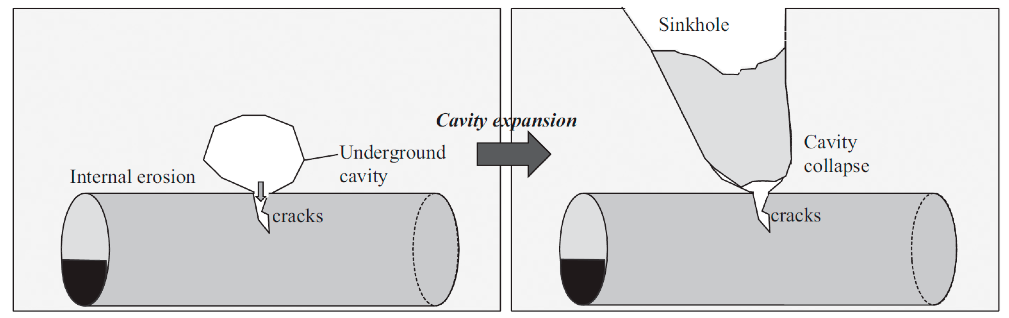
  • The process of ground subsidence occurrence is cavity formation around the groundwater leakage point, either by ground loosening or by external soil erosion, cavity expansion, and ceiling collapse due to insufficient support within the cavity. These mechanisms are repeated until the collapse of the soil specimen.
  • The way ground water is supplied and leaked shows the difference in the ground subsidence mechanism. The ground loosening caused by a succession of water supply and drainage cycles leads to a faster collapse than a continuous leakage system.
  • A succession of fast water supply and drainage cycles leads to a faster collapse than slow water supply and drainage cycles.

Author Contributions

T.K. organized the paperwork, performed the 1 g model tests and completed the evaluation of ground subsidence mechanism caused by defected sewer pipes; S.-Y.J. initially suggested the idea, and helped with the centrifuge tests; Y.-H.J. processed the data collected from the model tests and interpreted the data; D.-S.K. supervised the research activities and provided guidance and suggestions; all authors contributed to the writing of each part.

Acknowledgments

This research was supported by the Korea Agency for Infrastructure Technology Advancement under the Ministry of Land, Infrastructure and Transport of the Korean government. (Project Number: 17SCIP-B108153-03).

Conflicts of Interest

The authors declare no conflict of interest.

References

  1. Kuwano, R.; Horii, T.; Kohashi, H.; Yamauchi, K. Defects of sewer pipes causing cave-in’s in the road. In Proceedings of the 5th International Symposium on New Technologies for Urban Safety of Mega Cities in Asia, Phuket, Thailand, 16–17 November 2006. [Google Scholar]
  2. Hachiya, M.; Tohda, J.; Tokumasu, K.; Takatsuka, Y.; Sano, Y. A new design method for buried pipelines subjected to differential ground settlement. In Proceedings of the 15th International Conference on Soil Mechanics and Geotechnical Engineering, Istanbul, Turkey, 31 August 2001; pp. 1319–1322. [Google Scholar]
  3. Tohda, J.; Hachiya, M. Response and design of buried pipelines subjected to differential ground settlement. In Proceedings of the 16th International Conference on Soil Mechanics and Geotechnical Engineering, Osaka, Japan, 12–16 September 2005; pp. 1659–1662. [Google Scholar]
  4. Mukunoki, T.; Kumano, N.; Otani, J.; Kuwano, R. Visualization of three dimensional failure in sand due to water inflow and soil drainage from defective underground pipe using X-ray CT. Soils Found. 2009, 49, 959–968. [Google Scholar] [CrossRef]
  5. Mukunoki, T.; Otani, J.; Nonaka, S.; Horii, T.; Kuwano, R. Evaluation of cavity generation in soils subjected to sewerage defects using X-ray CT. In Advances in X-ray Tomography for Geomaterials; John Wiley & Sons: Hoboken, NJ, USA, 2006; pp. 365–371. [Google Scholar]
  6. Indiketiya, S.; Jegatheesan, P.; Rajeev, P. Evaluation of defective sewer pipe–induced internal erosion and associated ground deformation using laboratory model test. Can. Geotech. J. 2017, 54, 1184–1195. [Google Scholar] [CrossRef]
  7. Seoul Metropolitan Government. Seoul Metropolitan Government to Issue the Result of Investigation on ‘Road Cave-In’, and Special Countermeasure; Seoul Metropolitan Government: Seoul, Korea, 2014.
  8. Jo, Y.S.; Cho, S.H.; Jang, Y.S. Field investigation and analysis of ground sinking development in a metropolitan city. Environ. Earth Sci. 2016, 75, 1353. [Google Scholar] [CrossRef]
  9. Asahi. (2016/11/08). Available online: www.asahi.com/topics/word/%E5%8D%9A%E5%A4%9A%E9%A7%85%E5%89%8D%E9%99%A5%E6%B2%A1.html (accesed on 25 April 2018). (In Japanese).
  10. Nishi Nippon. (2016/11/08). Available online: www.nishinippon.co.jp/feature/attention/article/301843/ (accesed on 25 April 2018). (In Japanese).
  11. Youtube. (2016/11/07). Available online: https://www.youtube.com/watch?v=LJB1NKe0r2o (accesed on 25 April 2018). (In Japanese).
Figure 1. Sinkhole and internal erosion caused by a sewer pipe defect.
Applsci 08 00679 g001
Figure 2. Front view of the model box.
Applsci 08 00679 g002
Figure 3. Schematic of the test set-up.
Applsci 08 00679 g003
Figure 4. Continuous supply tests (Cases 1 and 2).
Applsci 08 00679 g004
Figure 5. Repeated supply tests (Cases 3, 4 and 5).
Applsci 08 00679 g005
Figure 6. Cavity initiation and development around the opening.
Applsci 08 00679 g006
Figure 7. Pore pressure and suction for the continuous water supply cases: (a) Pore pressure (Case 1 and 2); (b) Suction (Case 1 and 2).
Applsci 08 00679 g007
Figure 8. Ground subsidence process with the pore pressure for repeated water supply, Case 3: (a) Pore pressure for the Case 3 test; (b) Part A enlarged; (c) Cavity expansion and contraction of Case 3 (17th cycle, 1 and 2 in (b)); (d) Cavity expansion and contraction of Case 3 (18th cycle, 3 and 4 in (b)).
Applsci 08 00679 g008
Figure 9. Ground subsidence process with pore pressure for repeated water supply, Case 3: (a) Pore pressure for Case 3 test; (b) Pore pressure distribution of Case 3 (Part B enlarged); (c) Cavity expansion and contraction of Case 3 (48th cycle, 5 in (b)); (d) Cavity expansion and contraction of Case 3 (48th cycle, 6 in (b)).
Applsci 08 00679 g009aApplsci 08 00679 g009b
Figure 10. Ground subsidence process with the pore pressure for repeated water supply, Case 5: (a) Pore pressure for the whole test (Case 5); (b) Pore pressure distribution of Case 5 (A part enlarged); (c) Cavity expansion and contraction of Case 5 (9th cycle, 1 and 2 in (b)); (d) Cavity expansion and contraction of Case 5 (10th cycle, 3 and 4 in (b)).
Applsci 08 00679 g010aApplsci 08 00679 g010b
Figure 11. Ground subsidence process with the pore pressure for repeated water supply, Case 5: (a) Pore pressure for the whole test (Case 5); (b) Pore pressure distribution of Case 5 (B part enlarged); (c) Cavity expansion and contraction of Case 3 (18th cycle, 5 in (b)); (d) Cavity expansion and contraction of Case 5 (18th cycle, 6 in (b)).
Applsci 08 00679 g011
Figure 12. Maximum suction of each cycle by tensiometer location.
Applsci 08 00679 g012
Figure 13. Settlement of each case for the whole test.
Applsci 08 00679 g013
Figure 14. Effect of buoyancy shown by the upward settlement: (a) Settlement of Case 4; (b) Settlement of Case 5; (c) Close-up of black circles in (a); (d) Close-up of black circle in (b).
Applsci 08 00679 g014
Figure 15. Cavity expansion and contraction cycle by water supply mode: (a) Typical cavity expansion and contraction process (continuous water supply); (b) Typical cavity expansion and contraction process (cyclic water supply).
Applsci 08 00679 g015
Figure 16. Risk according to the water supply mode.
Applsci 08 00679 g016
Figure 17. Summary of ground subsidence procedure: (a) Wter leakage and cavity formation; (b) Water drainage, closing of cavity above leakage, and loosened soil and cavity formation; (c) Repetition of water supply/drainage cycles inducing cavity expansion/contraction with an increase in cavity size and loosened soil area; (d) Final ground surface subsidence.
Applsci 08 00679 g017
Table 1. Physical properties of silica sand.
IndexValue
Specific gravity (Gs)2.63
#200 sieve passing ratio (%)0.9
Maximum dry density ( kN / m 3 )15.5
Minimum dry density ( kN / m 3 )12.3
Particle size (mm)D100.194
D500.322
D600.344
Unified soil classification system (USCS)SP
Uniformity constant (Cu)1.77
Plasticity index (PI)Non-plastic (NP)
Table 2. Test cases.
Water Head (cm)Continuous Water Supply15 s Supply & Drainage Cycles60 s Supply & Drainage Cycles
177Case 1Case 3Case 5
130Case 2Case 4-
Table 3. Number of cycles and corresponding collapse time.
Time (s)ContinuousCyclic
15 s60 s
Case 1Case 2Case 3Case 4Case 5
Collapse time2521No settlement150715322011
Total water supply time2521-7507651020
Total cycles--505117

