Article

Investigation into the Effects of the Variable Displacement Mechanism on Swash Plate Oscillation in High-Speed Piston Pumps

State Key Laboratory of Fluid Power and Mechatronic Systems, School of Mechanical Engineering, Zhejiang University, Hangzhou 310027, China
*
Author to whom correspondence should be addressed.
Appl. Sci. 2018, 8(5), 658; https://doi.org/10.3390/app8050658
Submission received: 6 March 2018 / Revised: 30 March 2018 / Accepted: 20 April 2018 / Published: 24 April 2018
(This article belongs to the Section Mechanical Engineering)

Abstract

:
High-speed, pressure-compensated variable displacement piston pumps are widely used in aircraft hydraulic systems for their high power density. The swash plate is controlled by the pressure-compensated valve, which uses pressure feedback so that the instantaneous output flow of the pump is exactly enough to maintain a presetting pressure. The oscillation of the swash plate is one of the major excitation sources in the high-speed piston pump, which may cause lower efficiency, shorter service life, and even serious damage. This paper presents an improved model to investigate the influence of the variable displacement mechanism on the swash plate oscillation and introduces some feasible ways to reduce oscillation of the swash plate. Most of the variable structural parameters of the variable displacement mechanism are taken into consideration, and their influences on swash plate oscillation are discussed in detail. The influence of the load pipe on the oscillation of the swash plate is considered in the improved model. A test rig is built and similarities between the experiments and simulated results prove that the simulation model can effectively predict the variable displacement mechanism state. The simulation results show that increasing the volume of the outlet chamber, the spring stiffness of the control valve, the action area of the actuator piston, and offset distance of the actuator piston can significantly reduce the oscillation amplitude of the swash plate. Furthermore, reducing the diameter of the control valve spool and the dead volume of the actuator piston chamber can also have a positive effect on oscillation amplitude reduction.

1. Introduction

High-speed, pressure-compensated piston pumps are widely used in aircraft hydraulic systems for their high power density. As a key component in the variable displacement mechanism, the swash plate is adjusted through the action of a pressure-compensated control valve, which uses pressure feedback so that the instantaneous output flow of the pump is exactly enough to maintain a presetting pressure. Reduction of the pressure pulsation and vibration of the piston pump, caused by the fluid–solid interaction, is a constant subject of research. The vibration of the high-speed piston pump can shorten its service life and negatively influence flight safety. The oscillating swash plate is one of the major excitation sources in a high-speed piston pump, which is caused by the actuator piston and the piston-slipper units. Currently, research into the swash plate mainly focuses on the torque from the pumping pistons, the toque from both the pumping pistons and the actuator piston, and the control characteristics of the piston pump systems.
Many studies have considered the torques on the swash plate from the pumping pistons in their models. Zeiger et al. [1] have conducted a dynamic analysis of the swash plate control of an axial piston pump and found that the pump shaft rotational speed and the discharge volume affect the dynamic behavior. Moreover, the averaged torque on the swash plate at zero angular velocity was calculated and compared to experimental results, indicating a good correlation. Manring et al. calculated the torques through the given approximate distribution of the pressure in the pumping pistons [2,3]. To improve accuracy, some studies deduced the differential equation of the pumping piston pressure from the kinematical equations and the continuity equations of flow, which consider the pressure overshoot and pressure undershoot in the transition regions [3,4]. Ericson [5] investigated the oscillations of swash plates caused by pumping piston forces acting on the swash plate and surmised that the flow pulsations have minor variations between fixed and oscillating swash plates. Miller [6] designed a simplified pump structure, consisting of the swash plate and the housing, and measured the interfacial properties of the bearing interface between the swash plate and the pump housing under static, modal, and transient conditions. Fornarelli et al. [7] analyzed the forces acting on the swash plate in stationary and non-stationary conditions using the software LMS-AMESim®. Liu et al. [8] simulated the single pumping piston torque on the swash plate based on a hydraulic–mechanical co-simulation model and reduced the flow ripple rates through integration and optimization. Pan et al. [9] established a flexible multi-body dynamic model of an axial piston pump and found that the main noise source is the excitation force of the swash plate on the housing.
The actuator piston in the variable displacement mechanism constitutes another main part of the torque on the swash plate. Kim et al. [10] conducted a study on the sensitivity of the outlet pressure control to certain parameters within the pump system, and the total torque on yoke due to the force of pumping pistons and bias pistons was given. However, the high-frequency swash plate oscillation was not discussed. Norhirni et al. [11] derived the equations for the actuator forces applied on the swash plate, which could be used to obtain the control and containment requirements for any steady-state operating condition of any pump with similar swash plate design. The control valve and actuator were modeled by Ericson to investigate the oscillations on the swash plate [12]. He found out that the oscillations of the swash plate become bigger at small speeds, small setting angles, and larger pressures. Achten [13] built a simulation model to investigate swash plate oscillation in a variable displacement floating cup pump and came to similar conclusions to Ericson. Maiti et al. [14] measured the low-frequency variation in the swash plate control torque when the swash plate starts moving at the vicinity of the set pressure zone, and the simulated torque shows similarities with the experimental result, except for at the low flow zone. Milind et al. [15,16] developed a multi-body dynamic model without the consideration of fluid to study the bearing forces, control piston force, swash plate motion, and torque ripple. Milind summarized the variation of the angular oscillations of the swash plate about the axis perpendicular to the driveshaft.
Other scholars have also studied the control characteristics of the piston pump system. They analyzed the stability of the load-sensing (LS) controlled variable displacement pump system and found that the LS systems are prone to oscillation or even unstable behavior, because the load dynamics and the pump dynamics become inherently heavily coupled through an LS mechanism [17,18,19]. Kim et al. [20] used an electronic angle sensor and an acceleration sensor to measure the dynamic state of the swash plate of a modified high-bandwidth pump control system. They achieved adjustable swash plate vibration reduction at the desired frequency by the active vibration control. In the studies on the electro-hydraulically controlled variable displacement pumps [21,22,23,24], the swash plate angle of the piston pump was measured and controlled, but no obvious oscillatory behavior of the swash plate angle was noticed. The displacement angle was also measured with a Hall-effect sensor in a hardware-in-the-loop simulation test rig by Larsson et al.; he used a pole placement approach combined with a lead-compensator controller architecture to control the swash plate angle [25,26]. Ma et al. [27] designed a fault diagnosis method for an intelligent hydraulic pump system using a nonlinear unknown input observer based on the output pressure and swash plate angle signals.
In previous studies, although some researches modeled both the variable displacement mechanism and the piston-slipper units, they did not analyze the influence of the structure parameters on the swash plate dynamics in the piston pump. In the high-speed piston pump, the vibration of the swash plate could lead to serious damage of the pump. Therefore, this paper presents an improved model for investigating the dynamic performance of the swash plate at a high frequency, analyzing and optimizing its structure parameters.

2. Theoretical Model

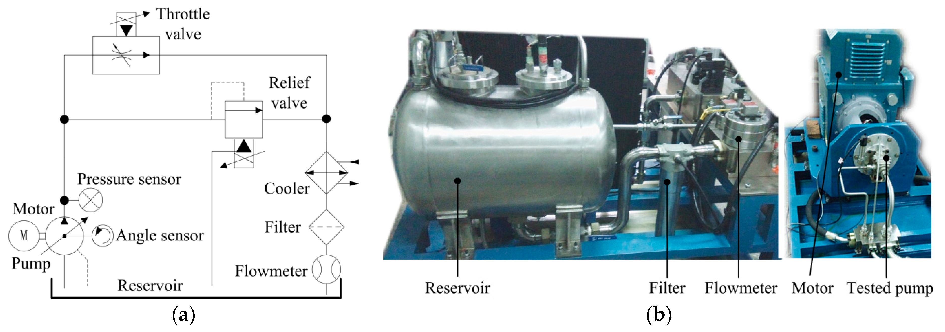
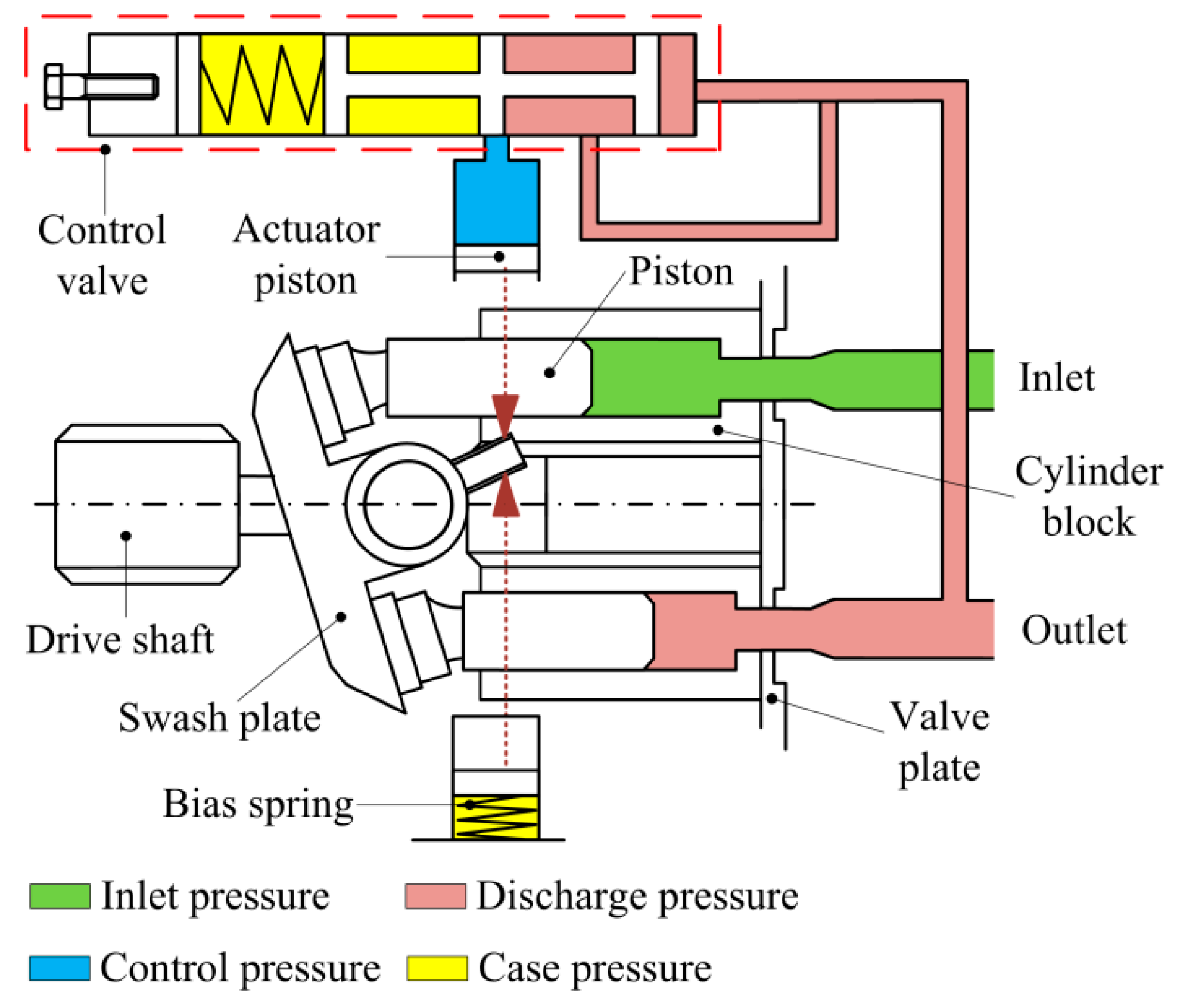
Figure 1 presents the basic principle of the high-speed, pressure-compensated piston pump. The oscillation of the swash plate is defined by the bias spring, the actuator piston, and the piston-slipper units. The swash plate with the bias spring can be treated as a second-order system (with inertia Js, damping coefficient bs, and spring stiffness Ks). Two driving torques act on the swash plate system, namely the torque Tp from the nine piston-slipper units and the torque Ta from the variable displacement mechanism.
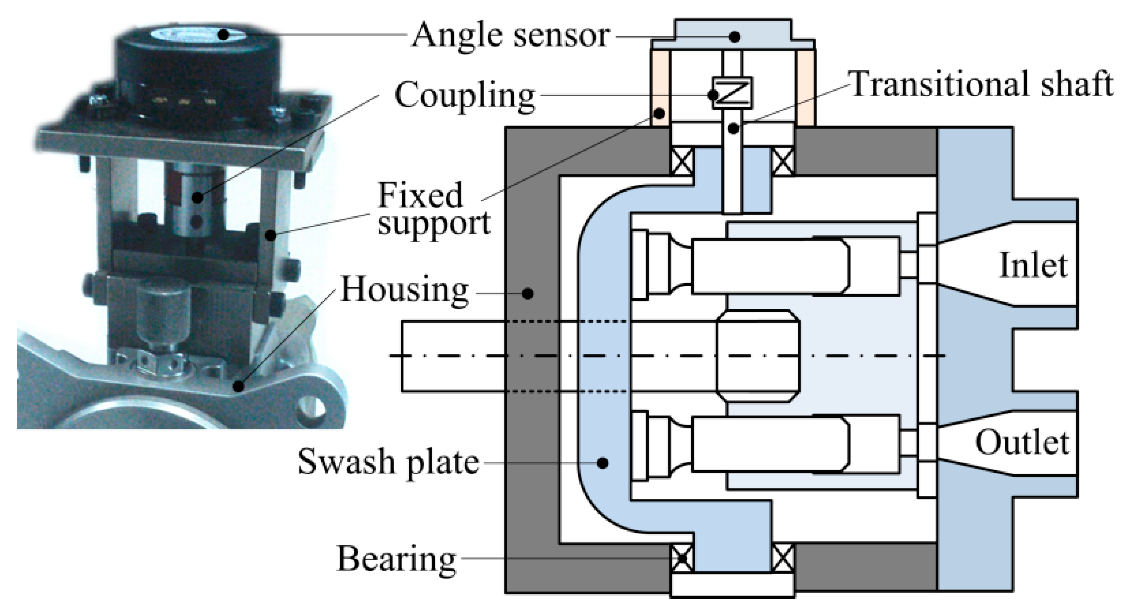
The control mechanism of the swash plate consists of the actuator part, the control valve part, the outlet chamber, the load, and the pipes (shown in Figure 2). The ripple flow input Q0 from the pumping pistons causes a pulsation pressure P0 in the outlet chamber V0. Most of the pressured oil flows to the load valve through a long pipe (with diameter d4, length l4), and the rest goes to the chamber V1 in front of the valve spool through a long, slim pipe (with diameter d1, length l1). The pressure P1 force acting on the valve spool against the spring force drives the valve spool to change the flow rate through the control valve. The oil flowing into or out of the actuator piston chamber V3 through a long slim pipe (with diameter d2, length l2) directly changes the chamber pressure P3, and hence the torque Ta on the swash plate.

2.1. Piston-Slipper Assembly

The torque from the pumping pistons to the swash plate can be given as follows:
T p = i = 1 n l i P i A p / cos φ
In Equation (1), li is identified as the moment arm of the ith slipper shoe relative to the rotation axis of the swash plate, Pi is pressure of the ith pumping piston chamber, and Ap is the action area of the pumping piston.
When the piston completely connects to the pump discharge region, the pumping piston pressure is equal to the discharge pressure (Pd). Similarly, the pumping piston pressure is the intake pressure (Pi) when the pumping piston is in the suction region.

2.2. Outlet Chamber

The flow in the outlet chamber can be divided into three parts: the input flow rate Q0, the flow rate Q01 to the control valve, and the flow rate Q04 to the load valve.
The total flow rate comes from the downward moving pumping pistons in the discharge region. According to the kinematic relationship, the ideal flow of each pumping piston is given as follows:
Q i = ω r p A p tan φ sin θ i
where ω is the angular velocity of the cylinder block, rp is the pitch radius of pumping piston and θi is the angular displacement of the ith pumping piston.
The kinematic flow fluctuation is the superposition of the flow ripples from different pumping pistons connected to the discharge port. Through Laplace transform, the flow rate to the load system can be expressed as follows:
Q 04 ( s ) = 1 Z 04 P 0 ( s )
where Z04 is the equivalent impedance of the load valve and the pipe between the outlet chamber and load valve.
Finally, the continuity equation of flow in the outlet chamber is given by the following:
Q 0 ( s ) Q 01 ( s ) Q 04 ( s ) = V 0 K o i l s P 0 ( s )
Equation (4) is also can be written as a four-pole pattern as follows:
[ P 0 ( s ) Q 0 ( s ) ] = A 0 [ P 0 ( s ) Q 01 ( s ) ] , where A 0 = [ 1 0 V 0 K o i l s + 1 Z 04 1 ]

2.3. Pipes

There are two long, slim pipes in the variable displacement mechanism and one pipe before the load valve. The series impedance Z(s) and parallel admittance Y(s) of a pipe (with diameter d, sectional area A, length l) can be given as follows:
Z ( s ) = ρ 0 A s + 8 π ρ 0 υ 0 A 2
Y ( s ) = C 0 s = A ρ 0 a 0 2 s
where v0 is the kinematic viscosity of the hydraulic oil, ρ0 is the density of the hydraulic oil, and a0 is the velocity of the pressure wave.
The characteristic impedance Zc(s) and propagator Γ(s) of a pipe can be expressed as follows:
Z c ( s ) = Z ( s ) / Y ( s ) = ρ 0 a 0 A 1 + 8 π υ 0 A s
Γ ( s ) = l Z ( s ) Y ( s ) = l s a 0 1 + 8 π υ 0 A s
Hence, the transfer function of the pipe behind the control valve can be expressed as a four-pole pattern as below:
[ P 2 ( s ) Q 2 ( s ) ] = A p 2 [ P 3 ( s ) Q 3 ( s ) ]
where the transfer matrix Ap2 is given by the following:
A p 2 = [ cosh Γ ( s ) Z c ( s ) sinh Γ ( s ) Z c 1 ( s ) sinh Γ ( s ) cosh Γ ( s ) ]
Similarly, the transfer function of the pipe before the control valve in the variable displacement mechanism and the pipe before the load valve can be expressed as follows:
[ P 0 ( s ) Q 01 ( s ) ] = A p 1 [ P 1 ( s ) Q 1 ( s ) ]
[ P 0 ( s ) Q 04 ( s ) ] = A p 4 [ P 4 ( s ) Q 4 ( s ) ]
where Ap1 and Ap4 are the transfer matrices of the two pipes.

2.4. Pressure Control Valve

The three-way control valve is the key component that regulates the pressure of the outlet chamber near the preset pressure. For small perturbations at the initial working point, the flow of the control valve can be linearized by means of an incremental method as below:
Δ q v = q v x v | 0 Δ x v + q v p l | 0 Δ p l = K q Δ x v + K c Δ p l
where Kq is the flow gain of the valve and Kc is the flow pressure coefficient.
Hence, the transfer function of the valve flow can be given by the following:
Q v ( s ) = K q X v ( s ) K c P 2 ( s )
For the moving spool of the control valve, the transfer function can be derived as follows:
P 1 ( s ) A v = m v s 2 X v ( s ) + b v s X v ( s ) + K v X v ( s )
The continuity equation of flow in the chamber between the spool and the pipe:
Q 1 ( s ) Q v ( s ) = A v s X v ( s ) + V 1 K o i l s P 1 ( s )
To summarize the dynamics of the control valve, Equations (15)–(17) are solved simultaneously to give the following result as a four-pole form:
[ P 1 ( s ) Q 1 ( s ) ] = G 1 ( s ) [ K c 1 G 2 ( s ) G 3 ( s ) ] [ P 2 ( s ) Q v ( s ) ] = A 1 v [ P 2 ( s ) Q v ( s ) ]
where G1(s), G2(s), and G3(s) can be given as follows:
G 1 ( s ) = m v s 2 + b v s + K v K q A v
G 2 ( s ) = K c s ( A v 2 m v s 2 + b v s + K v + V 1 K o i l )
G 3 ( s ) = K q A v + A v 2 s m v s 2 + b v s + K v + V 1 s K o i l
The flow of the chamber behind the valve spool V2 consists of the flow from the valve and the flow to the pipe and actuator piston chamber. The continuity equation of flow in this chamber is given as follows:
[ P 2 ( s ) Q v ( s ) ] = [ 1 0 V 2 K o i l s 1 ] [ P 2 ( s ) Q 2 ( s ) ] = A v 2 [ P 2 ( s ) Q 2 ( s ) ]

2.5. Actuator Piston

The pressure of the fluid in the actuator piston chamber is affected by the flow from the pipe Q3, the position of the actuator piston xa, and the leakage flow Ql3. Hence, the continuity equation of flow can be expressed as follows:
Q 3 ( s ) = A a s X a ( s ) + C 3 P 3 ( s ) + V 3 K o i l s P 3 ( s )
where C3 is the leakage flow coefficient.
Equation (23) can also be written as a four-pole form as below:
[ P 3 ( s ) Q 3 ( s ) ] = [ 1 0 C 3 + V 3 K o i l s A a s ] [ P 3 ( s ) X a ( s ) ] = A 3 a [ P 3 ( s ) X a ( s ) ]
The torque Ta from the actuator piston can be expressed as below:
T a ( s ) = l s [ P 3 ( s ) A a m a s 2 X a ( s ) b a s X a ( s ) ]
P 3 ( s ) X a ( s ) = 1 A a ( Z s l s 2 + m a s 2 + b a s ) = G 4 ( s )
where the equivalent impedance Zs can be expressed as follows:
Z s = T a ( s ) φ ( s ) = J s s 2 + b s s + K s l s 2
In Equation (27), ls is the moment arm length of the bias spring force and φ is the swash plate oscillation angle.

2.6. Load System

The load consists of a long pipe and a load valve. The transfer function of the load pipe is already given in Equation (13). The load valve is considered as a constant orifice (with the flow coefficient K4). Hence, the linear flow equation can be expressed as follows:
Q 4 ( s ) = 1 Z 4 P 4 ( s )
where Z4 is the equivalent impedance, and can be expressed as below:
Z 4 = K 4 1
Substituting Equation (28) into Equation (13), the equivalent impedance of the load system can be obtained as follows:
Z 04 = A p 4 ( 1 , 1 ) + A p 4 ( 1 , 2 ) A p 4 ( 2 , 1 ) + A p 4 ( 2 , 2 ) Z 4
where Ap4(i,j) is the element of the ith row and the jth column of the transfer matrix Ap4.

2.7. Whole Model

In summary, the improved model of the swash plate vibration containing the whole part of the variable displacement mechanism is given below.
[ P 0 ( s ) Q 0 ( s ) ] = A 0 A p 1 A 1 v A v 2 A p 2 A 3 a [ P 3 ( s ) X a ( s ) ] = A t o t [ P 3 ( s ) X a ( s ) ]
X a ( s ) = Q 0 ( s ) A t o t ( 2 , 1 ) G 4 ( s ) + A t o t ( 2 , 2 ) = P 0 ( s ) A t o t ( 1 , 1 ) G 4 ( s ) + A t o t ( 1 , 2 )
Similarly, the common model for the displacement controller design and evaluation of the piston pump system [15,16,17,18,19] can be modeled as follows:
[ P 0 ( s ) Q 0 ( s ) ] = A 00 A 3 a [ P 3 ( s ) X a ( s ) ] = A 0 t o t [ P 3 ( s ) X a ( s ) ]
where A00 is a simplified form of A0, which does not consider the influence of the load pipe (without Z04).
It can be seen from Equation (33) that the effects of the pipes before and after the control valve, the load pipe, and the chambers before and after the control valve are not included in the common model.

3. Model Validation

3.1. Test Rig

In order to evaluate the model of the swash plate of the piston pump, a test rig was built. The pump is driven by a variable-frequency motor, and its rotation speed can be varied from 0 to 8000 r/min. The specific parameter values used in this investigation are presented in Table 1.
Figure 3 shows the test principle. The flow load of the test rig is controlled by a throttle valve and the pressure load is controlled by a relief valve. A high-frequency pressure transducer is located at the pump outlet to measure the pressure fluctuation, its accuracy is more than 0.1%. The measurement schematic diagram of the swash plate angle is presented in Figure 4. The oscillation of the swash plate is transmitted to an angle transducer through two shafts and a coupling. The angle transducer is a resistance precision potentiometer, and has a high resolution of 0.007°. The detail photos of the test rig are in the Supplementary Materials.

3.2. Model Validation

The experimental results at 4000 rpm are presented in Figure 5a,b. The peak-to-peak value of the swash plate oscillation are 0.9°, 0.7°, and 0.6° at the three load flow rates, 1.5 L/min, 4.5 L/min, and 11.0 L/min, respectively. The average swash plate angles of the three sets of results are 2.7°, 4.6°, and 12.3°, respectively. It can be observed, through the structure of the variable displacement mechanism, that a higher load flow rate leads to a larger average angle of the swash plate, which also leads to a smaller average volume of the actuator piston chamber. To evaluate the variable displacement mechanism dynamic response, the oscillation ratio is defined as the ratio of angle oscillation amplitude per pressure pulsation amplitude, as in Equation (34). The fast Fourier transform (FFT) results of the oscillation ratio at 4000 rpm are presented in Figure 5c for comparison with the simulation results. The ratios of the three sets of experiments are approximately 7.5, 5.5, and 4.0, respectively. The result can be interpreted as confirmation that the larger the volume of the actuator piston chamber is, the larger the resulting oscillation ratio of the variable displacement mechanism.
ε = Φ φ min ( Φ φ ) max ( Φ φ ) min ( Φ φ ) / Φ p t min ( Φ p t ) max ( Φ p t ) min ( Φ p t )
where Φφ is the amplitude of the swash plate oscillation angle, Φpt is the amplitude of the outlet chamber pressure pulsation, and ε is the oscillation ratio.
As the rated working speed range of this high-speed pump is from 3500 rpm to 4500 rpm, the simulation and experiments are carried out in the frequency interval from 500 Hz to 700 Hz, which is equivalent to 3340 rpm to 4670 rpm. Figure 6a shows the comparison of the improved model results and the common model results at the flow rate 1.5 L/min. The common model is based on previous research on the piston pump system [20,21,22,23,24,25,26,27]. There are significant differences between the two results. To further validate the accuracy of the improved model, the results of three sets of experiments and simulations are shown in Figure 6b. The load flow rates of the three sets are 1.5 L/min, 4.5 L/min, and 11.0 L/min, and the average volume of the actuator piston chamber of the three series of experiments is less than 5 × 10⁻⁷ m3. The results coincide with each other well, and demonstrate that the higher the load flow rate, the smaller the oscillation ratio, which is also consistent with the following simulation results, as shown in Figure 7b. Furthermore, the oscillation ratio decreases rapidly with the increasing rotation speed, which means that the improved model results have far more similarities with the experimental results than the common model results.

4. Discussion

In order to demonstrate the influences of the variable displacement mechanism on the swash plate oscillation, the major parameters of the variable displacement mechanism are analyzed here. As the effects of the parameters inside the pump are difficult to measure directly, simulation analysis is a reasonably good method for this purpose. The simulation results of the amplitude and phase of the swash plate oscillation at the rotation speed 4000 r/min (600 Hz) are provided and discussed below.

4.1. The Volume of the Chambers

There are two oil chambers, as shown in Figure 2: the outlet chamber (V0) and the actuator piston chamber (V3). In Figure 7a,b, the amplitude and phase of the swash plate oscillation change dramatically with the volume of the outlet chamber and the actuator piston chamber. Conversely, the chambers before or behind the valve spool (V1 and V2) have little influence on oscillation, because of the narrow intervals of the changing volumes. When V0 is near 6 × 10⁻⁶ m3 or V3 is near 5 × 10⁻⁷ m3, the amplitude of the oscillation reaches the maximum, and the phase drops remarkably; approximately 170 degrees and 130 degrees, respectively.
Hence, a reasonable interval of the volume of the outlet chamber V0 and the actuator piston chamber V3 will minimize the oscillation amplitude of the swash plate. For the outlet chamber, it should be larger than 3 × 10⁻⁵ m3. It should not be too large, otherwise it can involve large bulk and heavy weight of the pump assembly. When the volume exceeds 6 × 10⁻⁵ m3, the effect of a larger volume on the reduction of vibration is not obvious. The volume V3 of the actuator piston chamber should be set between 3 × 10⁻⁷ m3 and 7 × 10⁻⁷ m3. However, a large volume may slow down the response speed of the swash plate, which also needs to be taken into consideration.

4.2. The Length and Diameter of the Pipes

In addition to the load pipe, there are two long, slim pipes in the variable displacement mechanism affecting the oscillation of the swash plate. There are severe resonance points when the pipe’s length increases in Figure 8a, which coincide with the pressure response of a typical pipe. Hence, resonance points of the swash plate oscillation are due to the length of the pipe when it equals the integral multiples of the pressure wavelength in the pipe. Increasing the load pipe diameter can significantly increase the amplitude of the oscillation, as shown in Figure 8b. The oscillation reaches its maximum at a diameter of 16 mm. Once the diameter of the load pipe exceeds 16 mm, the larger the diameter, the lower the oscillation amplitude. This is because the large diameter of the pipe can be considered as additional volume of the outlet chamber. The amplitude increases as the length of the pipe increases before the control valve in Figure 8c, and similar trends can be observed in Figure 8e. The changing amplitude range of the pipe behind the control valve is about 0.04, which is almost twice as large as the pipe before the control valve. The diameters of the two pipes have an almost converse influence on each other. The large diameter of the pipe before the control valve shows stronger capacitive characteristics than an additional volume of the outlet chamber. Meanwhile, the influence of the pipe diameter behind the control valve and the volume V3 of the actuator piston chamber show similar performance.
A short length and large diameter pipe before the control valve, and a short length and small diameter pipe behind the control valve, are a reasonable design choice to reduce the amplitude of the swash plate oscillation.

4.3. The Stiffness of the Springs

The influence of the spring stiffness on the swash plate oscillation is shown in Figure 9. The amplitude decreases by approximately 80% in the stiffness range of the control valve spring. Hence, choosing a stiff spring for the control valve can be a method to reduce the amplitude of the swash plate oscillation. It is also known from the simulation results that the stiffness of the swash plate spring has less influence on the swash plate oscillation than the control valve spring.

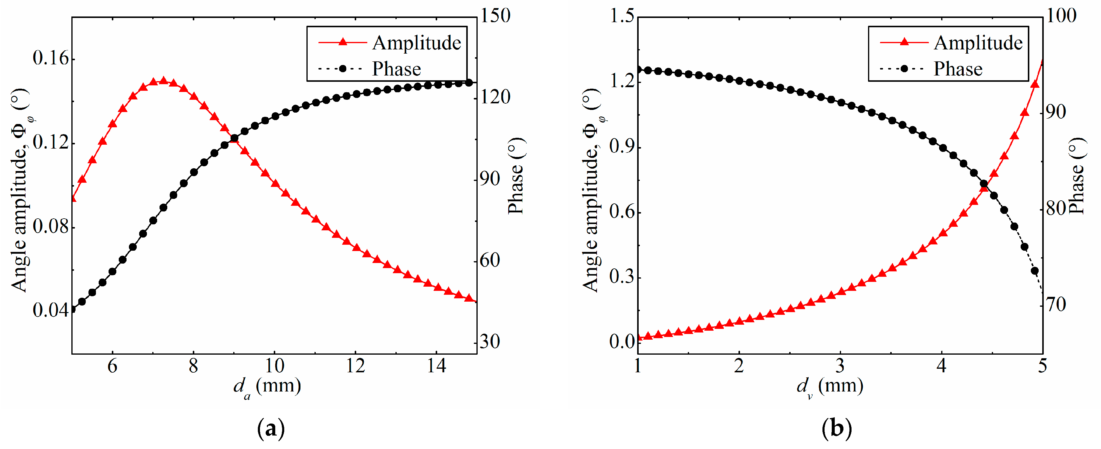
4.4. The Action Diameters

The action area of the actuator piston can dramatically affect the oscillation. There is a resonance point when the diameter of the actuator piston is near 7 mm in Figure 10a. Unlike the chambers in Figure 7, the phase of the swash plate oscillation increases rapidly near the resonance point. As shown in Figure 10b, the amplitude increases to about 1.3 in the changing range 1–5 mm.
In order to reduce the oscillation amplitude, the diameter of the actuator piston should keep away from the peak range. A reasonably large diameter should be considered in the design process, because a small action area may lead to slow response of the swash plate and a much larger action area may introduce additional weight on the pump. A reasonably small control valve spool may also be a good design, because a much smaller diameter may cause a much slower response speed of the swash plate.

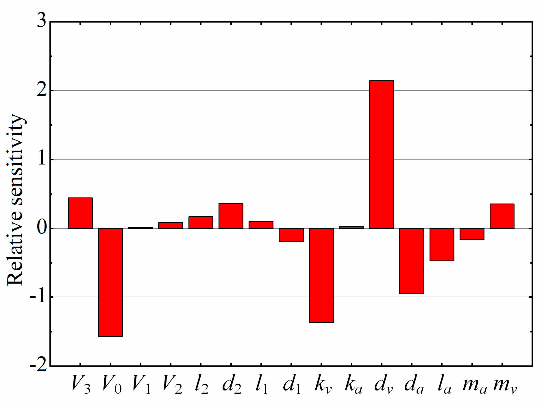
4.5. The Sensitivity of the Parameters

In order to characterize the influence of every structural parameter on the oscillation of the swash plate, the local relative sensitivity, based on the differential method, is given in Figure 11. We can see that the volume V0 of the outlet chamber, the stiffness kv of the control valve spring, the action area of the actuator piston, and offset distance la of the actuator piston are the four key parameters that have a large effect on the swash plate dynamic response. Reducing the values of the four parameters results in a significant increase in the amplitude of the swash plate oscillation and may even cause resonance. Hence, these four values need to be further increased to the appropriate sizes. On the other hand, the diameter dv of the control valve spool and the dead volume V3 of the actuator piston chamber also have a large effect on the swash plate dynamic response. A reasonable decrease in the values of the two parameters can further reduce the oscillation amplitude of the swash plate.

5. Conclusions

In this study, an improved model of a high-speed piston pump is proposed to investigate the influence of the variable displacement mechanism on the swash plate oscillation. A test rig has been built for validating the model. Similarities between the experiment results and simulation results have proven that the improved model can effectively predict the dynamics of the swash plate. Among the parameters, the outlet chamber volume, the control valve spring stiffness, the action area, and the offset distance of the actuator piston are the four major parameters that have a greater effect on the swash plate dynamic response. Furthermore, some feasible ways of reducing the oscillation of the swash plate have been discussed. Slightly reducing the values of the diameter of the control valve spool and the dead volume of the actuator piston chamber can significantly reduce the oscillation amplitude of the swash plate. Increasing the values of the volume of the outlet chamber, the stiffness of the control valve spring, the action area of the actuator piston, and the offset distance of the actuator piston also has a positive effect on the oscillation amplitude reduction.

Supplementary Materials

The following are available online at https://www.mdpi.com/2076-3417/8/5/658/s1, Figure S1: The photo of the drive module of the test rig, Figure S2: The photo of the oil source module of the test rig, Figure S3: The photo of the angle measurement module.

Author Contributions

Huayong Yang and Xiaoping Ouyang provided directional guidance to the research. Xiaoping Ouyang and Xu Fang conceived and designed the experiments; Xu Fang performed the experiments, analyzed the data and wrote the paper. Xiaoping Ouyang revised the paper.

Acknowledgments

This work was supported by the National Natural Science Foundation of China (Grant No. 51675473), the Fundamental Research Funds for the Central Universities (Grant No. 2017FZA4004), and Science Fund for Creative Research Groups of National Natural Science Foundation of China (Grant No. 51521064).

Conflicts of Interest

The authors declare no conflict of interest.

References

  1. Zeiger, G.; Akers, A. Dynamic analysis of an axial piston pump swashplate control. Proc. Inst. Mech. Eng. Part C 1986, 200, 49–58. [Google Scholar] [CrossRef]
  2. Manring, N.D. The control and containment forces on the swash plate of an axial-piston pump. J. Dyn. Syst. Meas. Control ASME 1999, 121, 599–605. [Google Scholar] [CrossRef]
  3. Zhang, X.; Cho, J.; Nair, S.; Manring, N. New swash plate damping model for hydraulic axial-piston pump. J. Dyn. Syst. Meas. Control ASME 2001, 123, 463–470. [Google Scholar] [CrossRef]
  4. Manring, N.D.; Damtew, F.A. The control torque on the swash plate of an axial-piston pump utilizing piston-bore springs. J. Dyn. Syst. Meas. Control ASME 2001, 123, 471–478. [Google Scholar] [CrossRef]
  5. Ericson, L. Swash plate oscillations due to piston forces in variable in-line pumps. In Proceedings of the 9th International Fluid Power Conference (9. IFK), Aachen, Germany, 24–26 March 2014. [Google Scholar]
  6. Miller, A.C. Assessment of Alternate Viscoelastic Contact Models for a Bearing Interface between an Axial Piston Pump Swash Plate and Housing. Ph.D. Thesis, The Ohio State University, Columbus, OH, USA, 2014. [Google Scholar]
  7. Fornarelli, F.; Lippolis, A.; Oresta, P.; Posa, A. A computational model of axial piston swashplate pumps. Energy Procedia 2017, 126, 1147–1154. [Google Scholar] [CrossRef]
  8. Liu, G.; Zhou, Z.; Qian, X.; Wu, X.; Pang, W. Multidisciplinary design optimization of a swash-plate axial piston pump. Appl. Sci. 2016, 6, 399. [Google Scholar] [CrossRef]
  9. Pan, Y.; Li, Y.; Huang, M.; Liao, Y.; Liang, D. Noise source identification and transmission path optimisation for noise reduction of an axial piston pump. Appl. Acoust. 2018, 130, 283–292. [Google Scholar] [CrossRef]
  10. Kim, S.D.; Cho, H.S.; Lee, C.O. A parameter sensitivity analysis for the dynamic-model of a variable displacement axial piston pump. Proc. Inst. Mech. Eng. Part C 1987, 201, 235–243. [Google Scholar] [CrossRef]
  11. Norhirni, M.; Hamdi, M.; Musa, S.N.; Saw, L.; Mardi, N.; Hilman, N. Load and stress analysis for the swash plate of an axial piston pump/motor. J. Dyn. Syst. Meas. Control ASME 2011, 133, 064505. [Google Scholar] [CrossRef]
  12. Ericson, L. Movement of the swash plate in variable in-line pumps at decreased displacement setting angle. In Proceedings of the 22nd International Congress of Mechanical Engineering (COBEM 2013), Ribeirão Preto, SP, Brazil, 3–7 November 2013. [Google Scholar]
  13. Achten, P.; Eggenkamp, S.; Potma, H. Swash plate oscillation in a variable displacement floating cup pump. In Proceedings of the 13th Scandinavian International Conference on Fluid Power, Linköping, Sweden, 3–5 June 2013; Linköping University Electronic Press: Linköping, Sweden, 2013; pp. 163–176. [Google Scholar] [CrossRef]
  14. Maiti, R.; Narayan, P. An experimental investigation on swash plate control torque of a pressure compensated variable displacement inline piston pump. In Proceedings of the 8th JFPS (Japan Fluid Power System Society) International Symposium on Fluid Power, Okinawa, Japan, 25–28 October 2011. [Google Scholar]
  15. Milind, T.; Mitra, M. A study on the dynamics and vibration behavior of an axial piston pump using combined MBD/FE approach. Procedia Eng. 2016, 144, 452–460. [Google Scholar] [CrossRef]
  16. Milind, T.; Mitra, M. A study on the flexible multibody dynamic modeling of an axial piston pump considering housing flexibility. Procedia Eng. 2016, 144, 1234–1241. [Google Scholar] [CrossRef]
  17. Krus, P. On Load Sensing Fluid Power Systems; Division of Fluid Power Control Department of Mechanical Engineering, Linkoping University: Linkoping, Sweden, 1988. [Google Scholar]
  18. Kim, S.D.; Cho, H.S.; Lee, C.O. Stability analysis of a load-sensing hydraulic system. Proc. Inst. Mech. Eng. Part A 1988, 202, 79–88. [Google Scholar] [CrossRef]
  19. Sakurai, Y.; Nakada, T.; Tanaka, K.; Ieee, I. Design method of an intelligent oil-hydraulic system (load sensing oil-hydraulic system). In Proceedings of the 2002 IEEE International Symposium on Intelligent Control, Vancouver, BC, Canada, 30 October 2002; pp. 626–630. [Google Scholar] [CrossRef]
  20. Kim, T.; Ivantysynova, M. Active vibration control of swash plate-type axial piston machines with two-weight notch least mean square/filtered-x least mean square (LMS/FxLMS) filters. Energies 2017, 10, 645. [Google Scholar] [CrossRef]
  21. Kemmetmueller, W.; Fuchshumer, F.; Kugi, A. Nonlinear pressure control of self-supplied variable displacement axial piston pumps. Control Eng. Pract. 2010, 18, 84–93. [Google Scholar] [CrossRef]
  22. Wei, J.; Guo, K.; Fang, J.; Tian, Q. Nonlinear supply pressure control for a variable displacement axial piston pump. Proc. Inst. Mech. Eng. Part I 2015, 229, 614–624. [Google Scholar] [CrossRef]
  23. Koivumaki, J.; Mattila, J. Adaptive and nonlinear control of discharge pressure for variable displacement axial piston pumps. J. Dyn. Syst. Meas. Control ASME 2017, 139. [Google Scholar] [CrossRef]
  24. Gao, Y.; Cheng, J.; Huang, J.; Quan, L. Simulation analysis and experiment of variable-displacement asymmetric axial piston pump. Appl. Sci. 2017, 7, 328. [Google Scholar] [CrossRef]
  25. Larsson, L.V.; Krus, P. Modelling of the swash plate control actuator in an axial piston pump for a hardware-in-the-loop simulation test rig. In Proceedings of the 9th FPNI Ph.D. Symposium on Fluid Power, Florianópolis, Brazil, 26–28 October 2016; American Society of Mechanical Engineers: New York, NY, USA, 2016; p. V001T001A044. [Google Scholar] [CrossRef]
  26. Larsson, L.V.; Krus, P. Displacement control strategies of an in-line axial-piston unit. In Proceedings of the 15th Scandinavian International Conference on Fluid Power, Linköping, Sweden, 7–9 June 2017; Linköping University Electronic Press: Linköping, Sweden, 2017; pp. 244–253. [Google Scholar] [CrossRef]
  27. Ma, Z.; Wang, S.; Shi, J.; Li, T.; Wang, X. Fault diagnosis of an intelligent hydraulic pump based on a nonlinear unknown input observer. Chin. J. Aeronaut. 2017, 31, 385–394. [Google Scholar] [CrossRef]
Figure 1. Pump structure diagram.
Applsci 08 00658 g001
Figure 2. Variable displacement mechanism. P0: the pressure of the discharge chamber; V0: the volume of the discharge chamber; Q0: the input flow rate; Q01: the flow rate to the control valve; Q04: the flow rate to the load valve; P1: the pressure of the chamber before the valve spool; V1: the volume of the chamber before the valve spool; P2: the pressure of the chamber behind the valve spool; V2: the volume of the chamber behind the valve spool; Qv: the flow rate of the control valve; Q2: the flow rate of the 2th pipe inlet; P3: the pressure of the actuator chamber; V3: the volume of the actuator chamber; Q3: the flow rate of the 2th pipe outlet; P4: the load pressure; Q4: the load flow rate; di: the diameter of the ith pipe; li: the length of the ith pipe; Av: the action area of the valve spool; Aa: the action area of the actuator piston; mv: the mass of the valve spool; xv: the displacement of the valve spool; xa: the displacement of the actuator piston; kv: the stiffness of the valve spring; Ta: the torque of the actuator piston. φ: the swash plate angle.
Applsci 08 00658 g002
Figure 3. The test rig. (a) Schematic sketch of the test rig and (b) structure of the test rig.
Applsci 08 00658 g003
Figure 4. Measurement schematic of the swash plate angle.
Applsci 08 00658 g004
Figure 5. Experimental results. (a) Swash plate angle; (b) outlet discharge pressure; and (c) fast Fourier transform (FFT) results of the ratio of angle oscillation to pressure pulsation.
Applsci 08 00658 g005
Figure 6. Comparison of simulated and experimental results. (a) Comparison of the improved and common model and (b) comparison of the improved model and experimental results.
Applsci 08 00658 g006
Figure 7. The influence of the volume of the chambers. (a) The outlet chamber (V0) and (b) the actuator piston chamber (V3).
Applsci 08 00658 g007
Figure 8. The influence of the pipes. (a) Length of the load pipe (l4); (b) diameter of the load pipe (d4); (c) length of the pipe before the control valve (l1); (d) diameter of the pipe before the control valve (d1); (e) length of the pipe behind the control valve (l2); and (f) diameter of the pipe behind the control valve (d2).
Applsci 08 00658 g008aApplsci 08 00658 g008b
Figure 9. The influence of the springs. (a) Stiffness of the control valve spring (kv) and (b) stiffness of the swash plate spring (ka).
Applsci 08 00658 g009
Figure 10. The influence of the action area of the chamber pressure. (a) Diameter of the actuator piston (da) and (b) diameter of the control valve spool (dv).
Applsci 08 00658 g010
Figure 11. The parametric sensitivity on the oscillation of the variable displacement mechanism.
Applsci 08 00658 g011
Table 1. Parameters of test rig.
ParameterValue
Pump:
 Discharge pressure, Po (MPa)21
 Rated speed range (r/min)3500~4500
 Pumping piston diameter, dp (mm)7.7
 Piston rotation radius, rpc (mm)27
 Outlet chamber, V0 (m3)3 × 10⁻⁵
 Chamber before valve spool, V1 (m3)1.9 × 10⁻⁷
 Chamber behind valve spool, V2 (m3)3.9 × 10⁻⁸
 Actuator piston chamber, V3 (m3)2 × 10⁻⁷
 Actuator piston diameter, da (mm)8
 Valve diameter, dv (mm)2.4
 Valve spring stiffness, kv (N mm−1)50
 Valve spool mass, mv (g)0.9
 Bias spring stiffness, ka (N·mm−1)22
 Swash plate moment of inertia, Js (Kg·m2)4.2 × 10⁻⁵
 Maximum swash plate angle, φmax (°)15.3
Test rig:
 Inlet pressure (MPa)0.5
 Oil density, ρ (Kg·m−3)833
 Oil bulk modulus, K (MPa)1000
 Oil temperature (°C)20~30
 Oil Dynamic viscosity, μ (Pa·s)8.33 × 10⁻³
 Sampling frequency (Hz)10240

