Power System Voltage Correction Scheme Based on Adaptive Horizon Model Predictive Control


Abstract
1. Introduction
2. Voltage Control Model Based on MPC
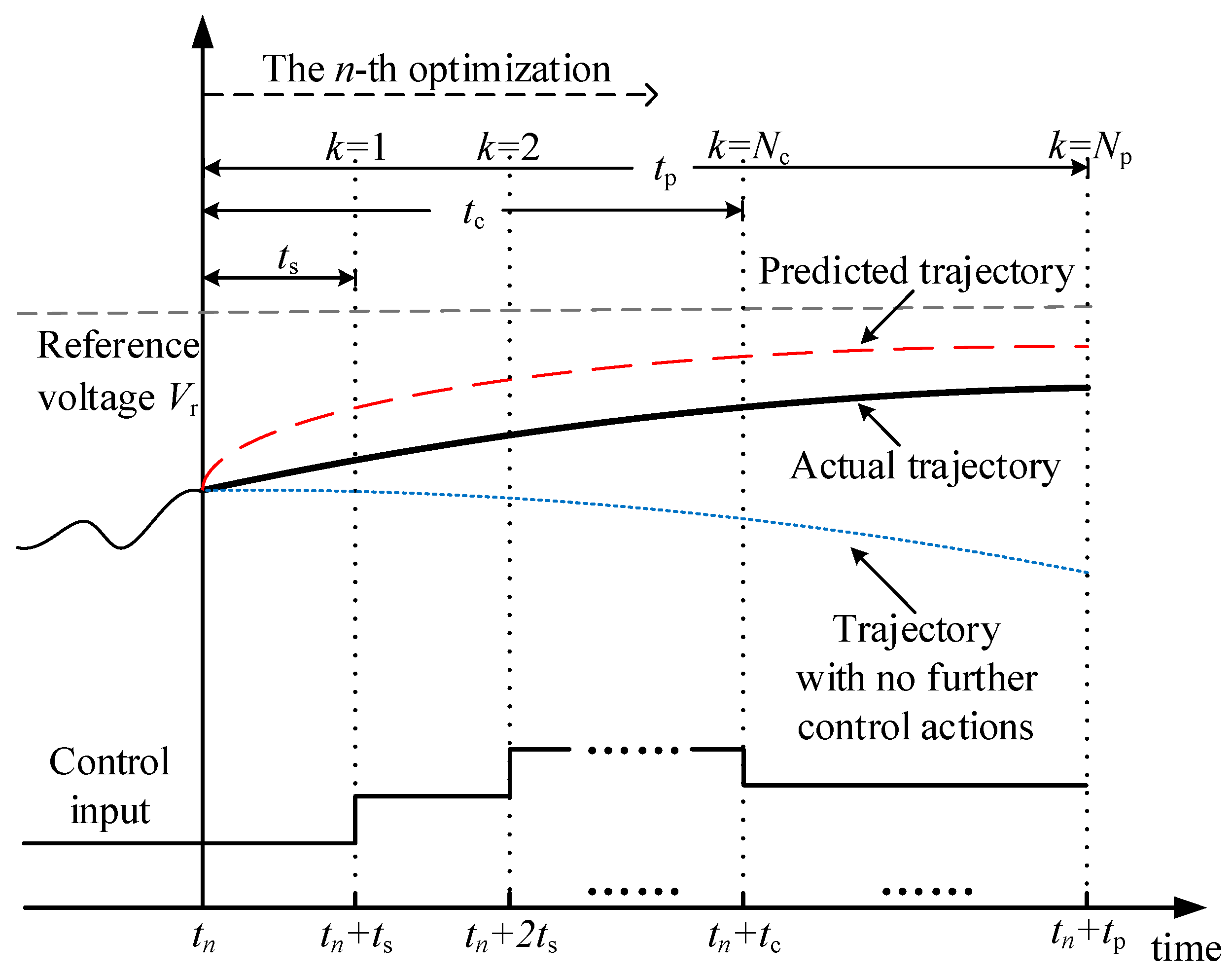
2.1. Voltage Prediction
2.2. Optimization Model
3. Adaptive Horizon Parameters
3.1. Principles for the Horizon Parameter Settings
- Sampling interval ts. The length of sampling interval ts should fulfill the requirements of measurement collection, data processing and optimization, which change little during the entire receding horizon optimization process. A constant value ts = 10 s is applied in the proposed scheme, which also matches the value used in the coordinated secondary voltage control in operation in practical systems [22].
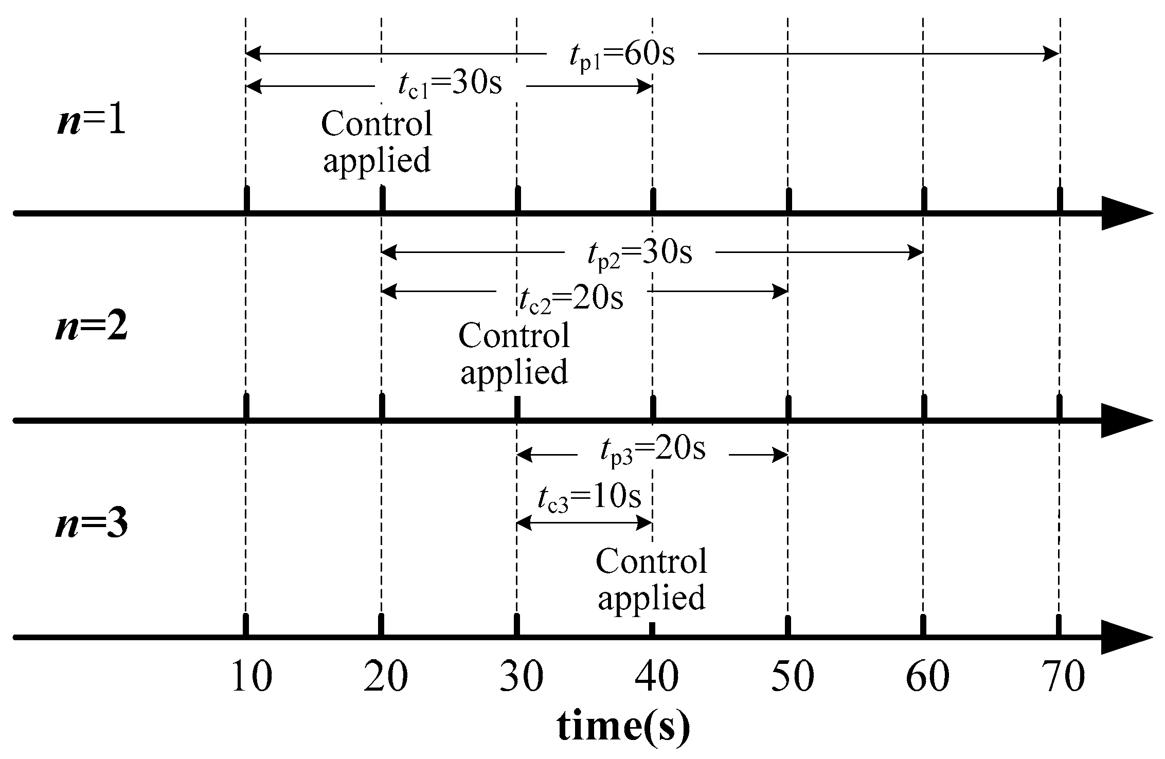
- Control horizon tc. With a constant sampling interval, the optimal length of the control horizon is related to the voltage evolution and response feature, which varies over the receding horizon optimization process. In this paper, the system voltage is predicted using a linear model as is introduced in Section 2. The sensitivity feature changes little if no disturbances occur during the optimization process [21], and the solved control variation is proportional to the detected voltage deviation. When severe voltage deviation is detected, the length of the control horizons should be short enough to meet the requirement of the voltage recovery speed and online computation time, and should be long enough to deal with modeling inaccuracies and measurement noise. As the receding horizon optimization progressed, the controlled voltages are gradually closer to its desired range, and smaller control variations are needed to accomplish the control objective. In this situation, shorter control horizon parameters could reduce settling times of the optimization process and computational effort.
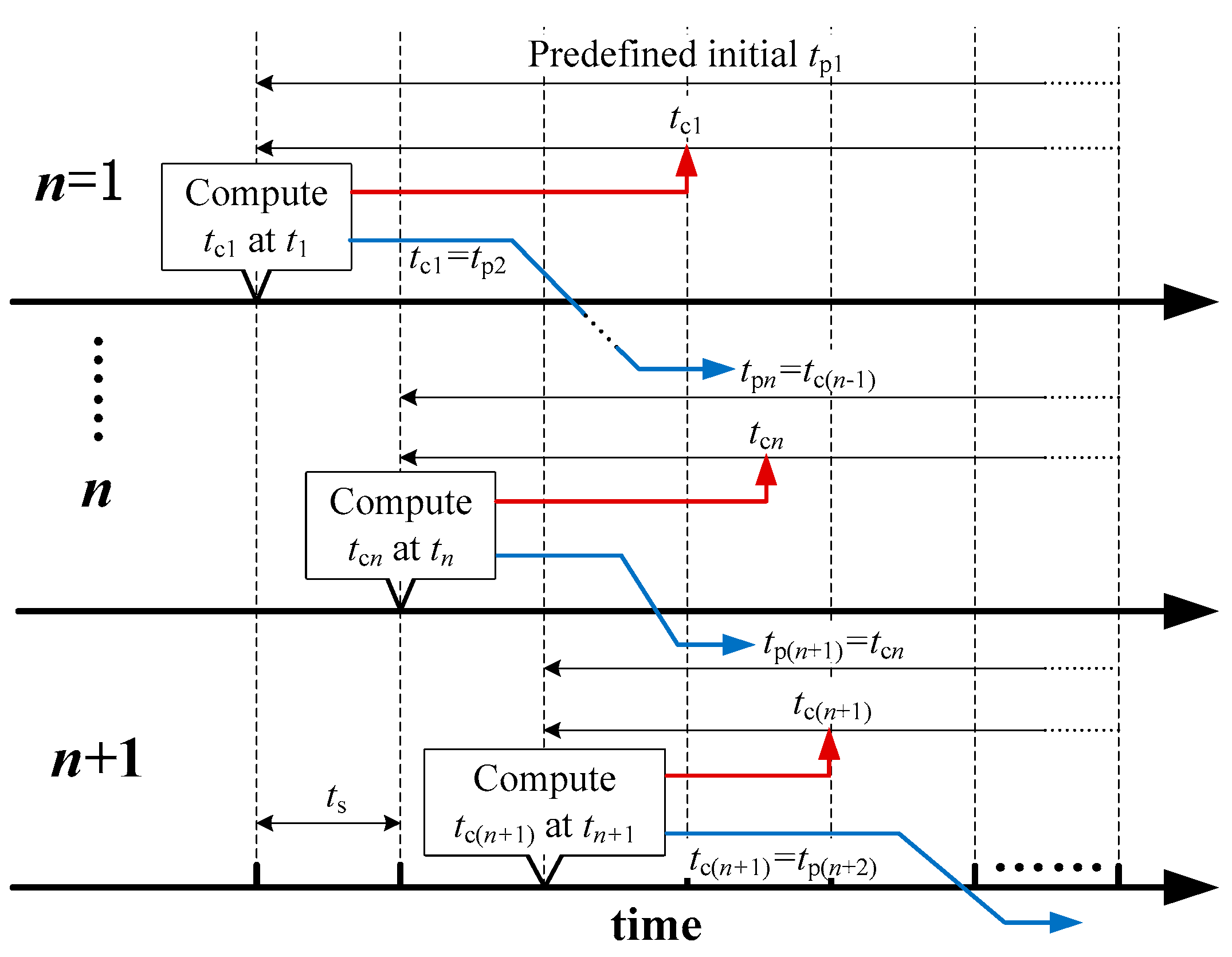
- Prediction horizon tp. The system response caused by the control actions are predicted within the prediction horizon, thus the length of the prediction horizon should be greater or equal to the length of the control horizon. When the controlled voltages are gradually stabilized to the steady state values, the necessity to consider changes happening beyond the control horizon is reduced from a computational viewpoint. Therefore, at the beginning of the MPC implementation, the length of the prediction horizon is set longer than the length of control horizon. As the receding horizon optimization progressed, the length of the prediction horizon gradually approaches the length of the control horizon, which could also save unnecessary computation time
3.2. Voltage Regulation Ability Evaluation
- (1)
- At tn, the voltage evolution trajectories are predicted within a predetermined prediction horizon [tn, tn + tpn] based on the trapezoidal numerical simulation. tpn is the length of prediction horizon applied in the n-th optimization. If the predicted voltage deviation of load bus i satisfies the inequality constraint (11) at the initial time instant t1, the voltage magnitude of bus i is determined as the evaluation target.where is the voltage magnitude of bus i without control at the prediction time instant (t1 + tp1) obtained by numerical simulation. DB is the control deadband. Vmax and Vmin initially presented in Equation (8) are subject to: Vmax = Vr + DB/2, Vmin = Vr − DB/2.
- (2)
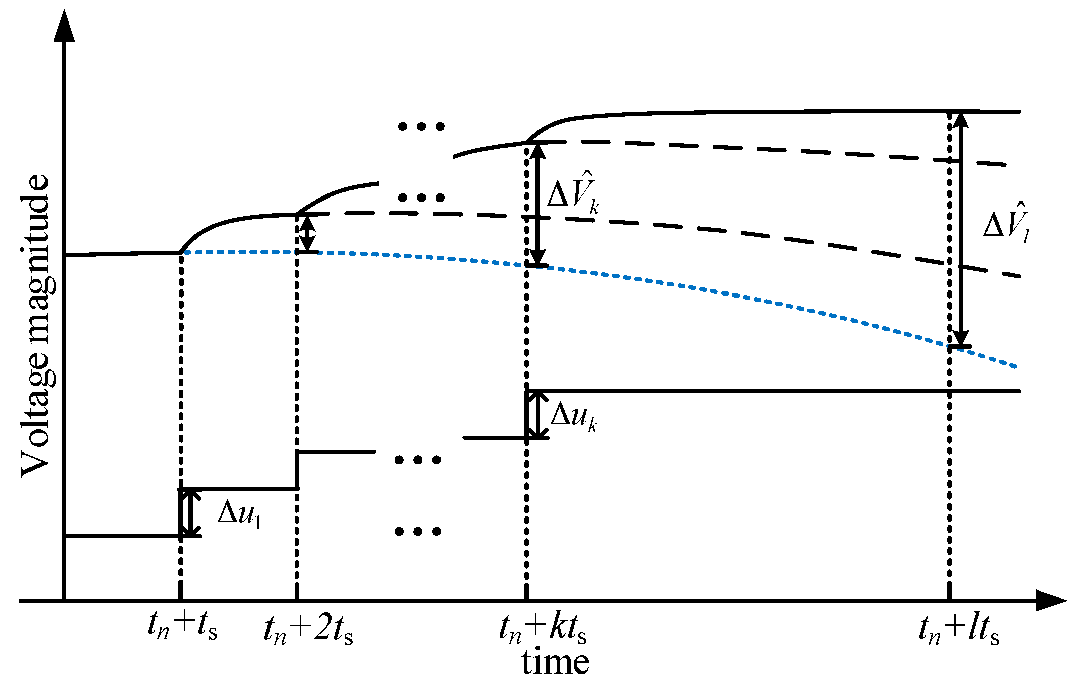
- The trajectory sensitivity matrix of the evaluation targets at time instant tn + tpn with respect to the control action of each step can be expressed as:where Sk(i, j) represents the trajectory sensitivity of the i-th evaluation target with respect to the j-th candidate control in the k-th control step. Ni and Nj are the total number of evaluation targets and available control actions respectively.
- (3)
- Based on the voltage prediction and trajectory sensitivity analysis, the maximum control target variation caused by controls applied at sampling point k is evaluated as follows.When , the optimization tends to increase the j-th control in order to raise (when and ) or reduce (when and ) the voltage magnitude of bus i towards its desired value. Under the inequality constraints (9) and (10), the predicted voltage magnitude variation of bus i reaches its maximum value when the variation of control j equals its maximum positive value:where is the predicted maximum variation of the evaluation target i at a future time instant tn + tpn, which is caused by the j-th control action applied at the sampling point k. is the j-th element in vector , representing the maximum value of the corresponding control variation. is the j-th element in vector umax.Similarly, when , the optimization tends to reduce the j-th control in order to reduce (when and ) or raise (when and ) the voltage magnitude of bus i towards its desired value. The maximum voltage variation value of bus i:where is the j-th element in vector umin.The maximum voltage variation of the i-th evaluation target considering all candidate control actions applied at sampling point k can be expressed as:
- (4)
- Considering multi control steps applied at the first m sampling points, The maximum voltage regulation ability at time instant tn + tpn caused by the control sequence (,, …, ) is evaluated as follows:where Va(i)m is the evaluated voltage regulation ability of the i-th evaluation target when the length of control horizon is mts.
3.3. Determination of the Horizon Parameters
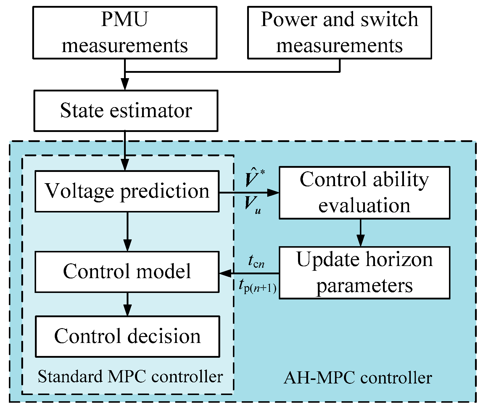
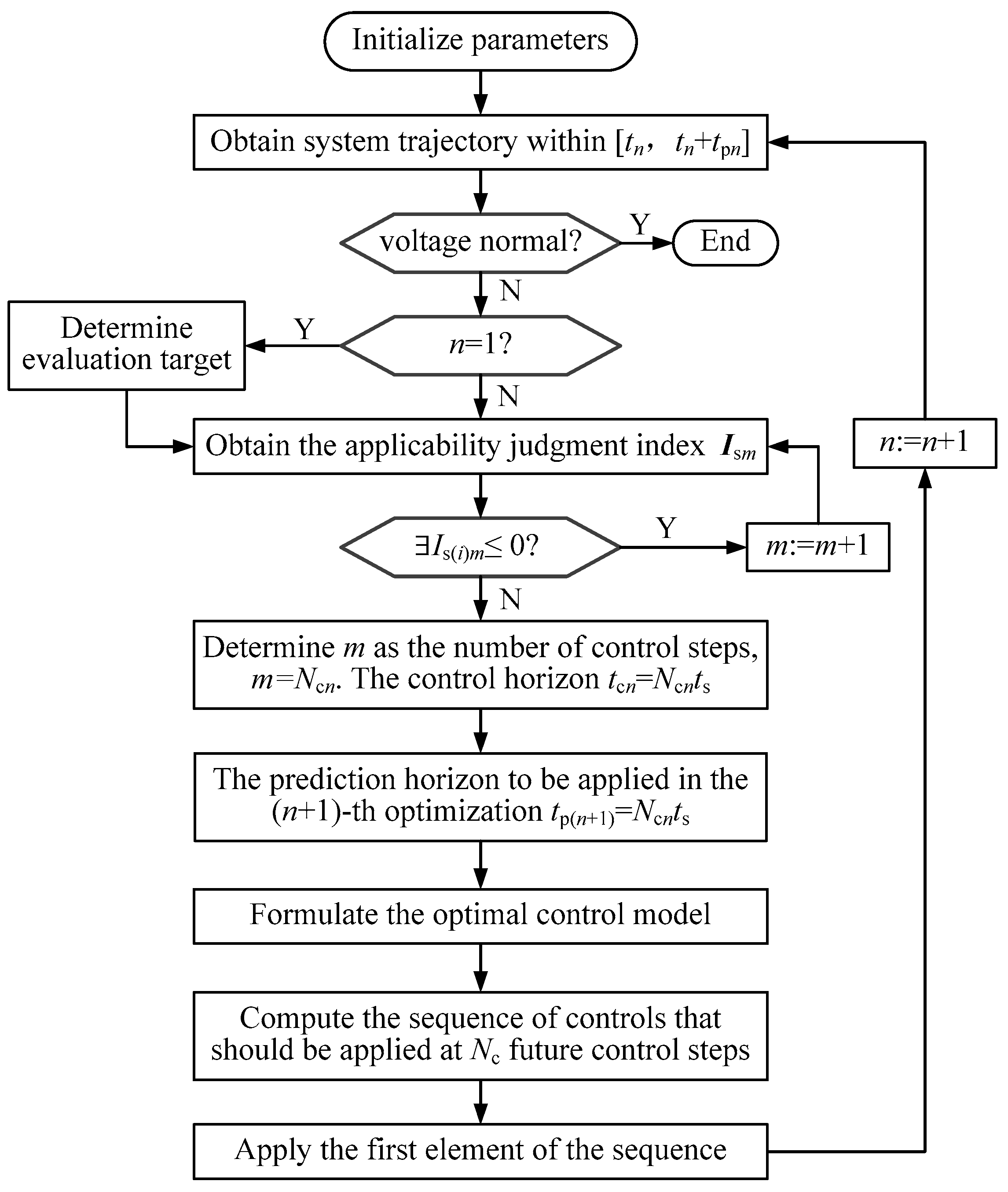
4. Voltage Correction Scheme Based on AH-MPC
- At a sampling point tn, trapezoidal numerical simulation is used to obtain the predicted system trajectory within the prediction horizon [tn, tn + tpn].
- The trajectory sensitivity is obtained as a by-product of the first step.
- Based on the predicted system trajectory and the trajectory sensitivity results, the adaptive horizon parameters are determined as is introduced in Section 3.
- The optimal control model is formulated according to Equations (7), (9), (10), (20), (21) and (22).
- By solving the optimal control model, the first step of the so computed control sequence is applied in the system at tn + ts.
- The above procedure is repeated at the initial time of the (n + 1)-th optimization.
5. Simulations
5.1. Case A: Nine-Bus Test System
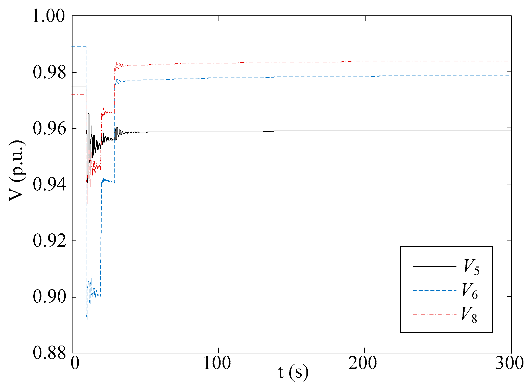
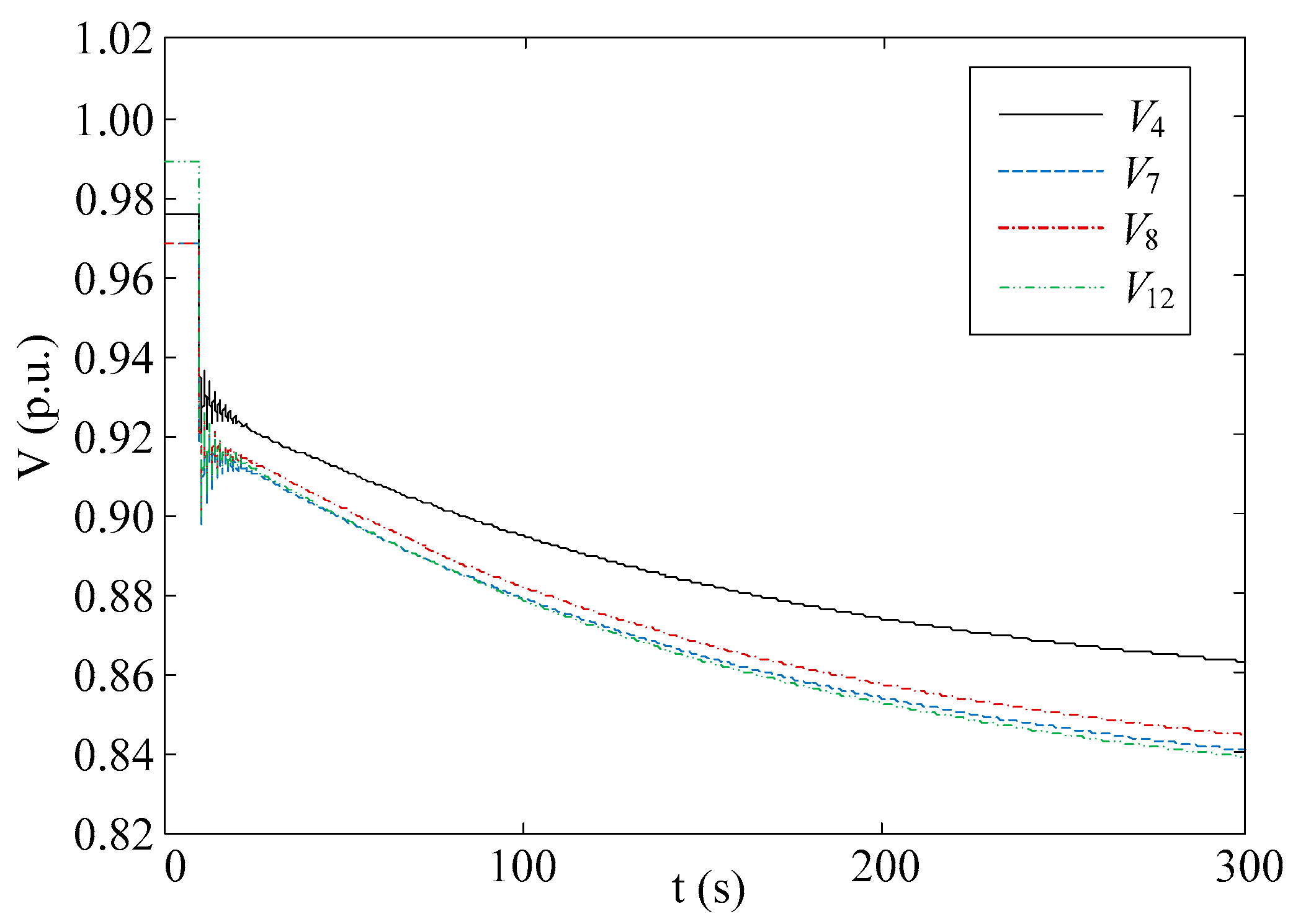
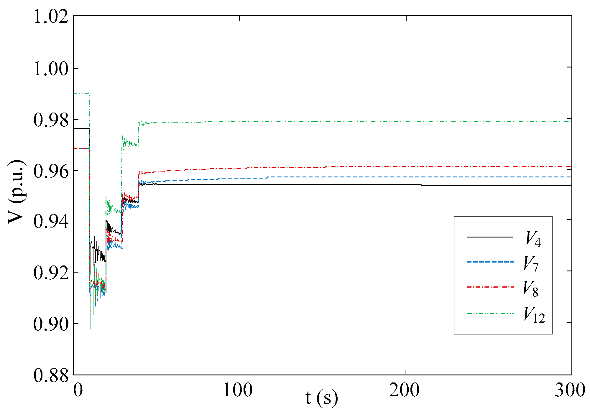
5.2. Case B: New England Test System
5.3. Simulating Modeling Inaccuracies
5.4. Control Performance Comparison
5.5. Discussion
- The simulations were carried out on a personal computer with the Matlab/Simulink-based tool. Both the hardware and software configuration can be significantly improved in a real-life application [27].
- The optimization problem can be solved concentrating on areas close to the disturbance with a simple representation used for other areas [21].
6. Conclusions
Author Contributions
Conflicts of Interest
References
- Van Cutsem, T.; Vournas, C. Voltage Stability of Electric Power Systems; Springer: Boston, MA, USA, 1998; pp. 193–210. [Google Scholar]
- Rawlings, J.B. Tutorial overview of model predictive control. IEEE Control Syst. Mag. 2000, 20, 38–52. [Google Scholar] [CrossRef]
- Larsson, M.; Hill, D.J.; Olsson, G. Emergency voltage control using search and predictive control. Int. J. Electr. Power Energy Syst. 2002, 24, 121–130. [Google Scholar] [CrossRef]
- Larsson, M.; Karlsson, D. Coordinated system protection scheme against voltage collapse using heuristic search and predictive control. IEEE Trans. Power Syst. 2003, 18, 1001–1006. [Google Scholar] [CrossRef]
- Jin, L.; Kumar, R.; Elia, N. Model predictive control-based real-time power system protection schemes. IEEE Trans. Power Syst. 2010, 25, 988–998. [Google Scholar] [CrossRef]
- Hiskens, I.A.; Gong, B. Voltage stability enhancement via model predictive control of load. Intell. Autom. Soft Comput. 2006, 12, 117–124. [Google Scholar] [CrossRef]
- Zhang, Y.; Zhang, W.; Chu, X.; Liu, Y. Real-time optimal voltage control using measurement-based aggregate load model. Electr. Power Syst. Res. 2014, 116, 293–300. [Google Scholar] [CrossRef]
- Ma, H.; Hill, D.J. Adaptive coordinated voltage control-Part I: Basic scheme. IEEE Trans. Power Syst. 2014, 29, 1546–1553. [Google Scholar] [CrossRef]
- Ma, H.; Hill, D.J. Adaptive coordinated voltage control—Part II: Use of learning for rapid response. IEEE Trans. Power Syst. 2014, 29, 1554–1561. [Google Scholar] [CrossRef]
- Moradzadeh, M.; Boel, R.; Vandevelde, L. Anticipating and coordinating voltage control for interconnected power systems. Energies 2014, 7, 1027–1047. [Google Scholar] [CrossRef]
- Martin, J.A.; Hiskens, I.A. Corrective model-predictive control in large electric power systems. IEEE Trans. Power Syst. 2017, 32, 1651–1662. [Google Scholar]
- Tang, Z.; Hill, D.J.; Liu, T.; Ma, H. Hierarchical voltage control of weak subtransmission networks with high penetration of wind power. IEEE Trans. Power Syst. 2018, 33, 187–197. [Google Scholar] [CrossRef]
- Zhao, H.; Wu, Q.; Wang, J.; Liu, Z.; Shahidehpour, M.; Xue, Y. Combined active and reactive power control of wind farms based on model predictive control. IEEE Trans. Energy Convers. 2017, 32, 1177–1186. [Google Scholar] [CrossRef]
- Zhao, H.; Wu, Q.; Guo, Q.; Sun, H.; Huang, S.; Xue, Y. Coordinated Voltage Control of a Wind Farm Based on Model Predictive Control. IEEE Trans. Sustain. Energy. 2016, 7, 1440–1451. [Google Scholar] [CrossRef]
- Guo, Y.; Gao, H.; Wu, Q.; Zhao, H.; Østergaard, J. Coordinated voltage control scheme for VSC-HVDC connected wind power plants. IET Renew. Power Gener. 2018, 12, 198–206. [Google Scholar] [CrossRef]
- Valverde, G.; Van Cutsem, T. Model predictive control of voltages in active distribution networks. IEEE Trans. Smart Grid. 2013, 4, 2152–2161. [Google Scholar] [CrossRef]
- Aristidou, T.; Valverde, G.; Van Cutsem, T. Contribution of distribution network control to voltage stability: A case study. IEEE Trans. Smart Grid. 2017, 8, 106–116. [Google Scholar] [CrossRef]
- Soleimani Bidgoli, H.; Van Cutsem, T. Combined Local and Centralized Voltage Control in Active Distribution Networks. IEEE Trans. Power Syst. 2018, 33, 1374–1384. [Google Scholar] [CrossRef]
- Balram, P.; Carlson, O.; Tuan, L.A. Demonstration of voltage control in a real distribution system using model predictive control. IET Gener. Transm. Distrib. 2017, 11, 3922–3929. [Google Scholar] [CrossRef]
- Hiskens, I.A.; Pai, M. Trajectory sensitivity analysis of hybrid systems. IEEE Trans. Power Syst. 2000, 47, 204–220. [Google Scholar] [CrossRef]
- Glavic, M.; Hajian, M.; Rosehart, W.; Van Cutsem, T. Receding-horizon multi-step optimization to correct nonviable or unstable transmission voltages. IEEE Trans. Power Syst. 2011, 26, 1641–1650. [Google Scholar] [CrossRef]
- Vu, H.; Pruvot, P.; Launay, C.; Harmand, Y. An improved voltage control on large-scale power system. IEEE Trans. Power Syst. 1996, 11, 1295–1303. [Google Scholar] [CrossRef]
- Hill, D.J. Nonlinear dynamic load models with recovery for voltage stability studies. IEEE Trans. Power Syst. 1993, 8, 166–176. [Google Scholar] [CrossRef]
- Karlsson, D.; Hill, D.J. Modelling and identification of nonlinear dynamic loads in power systems. IEEE Trans. Power Syst. 1994, 9, 157–166. [Google Scholar] [CrossRef]
- Rosenthal, R.E. GAMS—A User’s Guide; GAMS Development Corporation: Washington, DC, USA, 2010; pp. 1–3. [Google Scholar]
- Power System Test Case Archive. Available online: http://www.ee.washington.edu/research/pstca/ (accessed on 20 April 2018).
- Wen, J.; Wu, Q.; Turner, D.; Cheng, S.; Fitch, J. Optimal coordinated voltage control for power system voltage stability. IEEE Trans. Power Syst. 2004, 19, 1115–1122. [Google Scholar] [CrossRef]


| n | Is1 (p.u.) | Is2 (p.u.) | Control Horizon (s) | Prediction Horizon (s) |
|---|---|---|---|---|
| 1 | (−0.0195, 0.0128) | (0.0298, 0.0483) | 20 | 60 |
| 2 | (0.0285, 0.0429) | 10 | 20 |
| Time (s) | Control |
|---|---|
| 20 | Uref,G2 = 1.042 p.u., Uref,G3 = 1.033 p.u., C6 = 0.1 p.u., nt(12-11) = 1.0167 |
| 30 | Uref,G2 = 1.064, C6 = 0.2 p.u. |
| Time (s) | Control |
|---|---|
| 20 | Uref,G1 = 1.062 p.u., Uref,G2 = 1.025 p.u., Uref,G4 = 1.007 p.u., Uref,G5 = 1.036 p.u., Uref,G6 = 1.051 p.u., Uref,G7 = 1.069 p.u., Uref,G8 = 1.017 p.u., Uref,G9 = 1.025p.u., Uref,G10 = 1.023 p.u., C8 = 0.1 p.u., nt(12-11) = 1.0227, nt(12-13) = 1.0227, nt(19-20) = 1.0767 |
| 30 | Uref,G1 = 1.102 p.u., Uref,G2 = 1.065 p.u., Uref,G4 = 1.001 p.u., Uref,G5 = 1.017 p.u., Uref,G6 = 1.029 p.u., Uref,G7 = 1.061 p.u., Uref,G8 = 1.021 p.u., Uref,G9 = 1.002 p.u., Uref,G10 = 1.055 p.u., C8 = 0.2 p.u., nt(12-11) = 1.0394, nt(12-13) = 1.0227, nt(19-20) = 1.0934 |
| 40 | Uref,G1 = 1.128 p.u., Uref,G2 = 1.084 p.u., Uref,G4 = 0.998 p.u., Uref,G5 = 1.010 p.u., Uref,G6 = 1.004 p.u., Uref,G7 = 1.054 p.u., Uref,G8 = 1.031 p.u., Uref,G9 = 0.989 p.u., Uref,G10 = 1.079 p.u., C8 = 0.3 p.u., nt(12-11) = 1.0394, nt(12-11) = 1.0227, nt(12-11) = 1.1101 |
| n | Is1 (p.u.) | Is2 (p.u.) | Is3 (p.u.) | Control Horizon (s) | Prediction Horizon (s) |
|---|---|---|---|---|---|
| 1 | (−0.0211, −0.0301, −0.0275, −0.0198) | (0.0013, −0.0045, −0.0019, 0.0201) | (0.0196, 0.0152, 0.0177, 0.0510) | 30 | 60 |
| 2 | (0.0019, −0.0028, −0.0012, 0.0225) | (0.0201, 0.0169, 0.0184, 0.0534) | 20 | 30 | |
| 3 | (0.0148, 0.0144, 0.0177,0.0496) | 10 | 20 |
| Control Method | n | Time Consuming per Optimization (s) | tcn (s) | tpn (s) | Total Time Consuming (s) | ΔVoffset (p.u.) |
|---|---|---|---|---|---|---|
| AH-MPC | 1 | 1.919 | 30 | 60 | 3.567 | 3.4210 × 10⁻² |
| 2 | 1.079 | 20 | 30 | |||
| 3 | 0.569 | 10 | 20 | |||
| MPC | 1 | 1.914 | 30 | 60 | 7.525 | 3.6610 × 10⁻² |
| 2 | 1.876 | |||||
| 3 | 1.902 | |||||
| 4 | 1.833 |
© 2018 by the authors. Licensee MDPI, Basel, Switzerland. This article is an open access article distributed under the terms and conditions of the Creative Commons Attribution (CC BY) license (http://creativecommons.org/licenses/by/4.0/).
Share and Cite
Zhang, Y.; Liu, M.; Zhang, W.; Sun, W.; Hu, X.; Kong, G. Power System Voltage Correction Scheme Based on Adaptive Horizon Model Predictive Control. Appl. Sci. 2018, 8, 641. https://doi.org/10.3390/app8040641
Zhang Y, Liu M, Zhang W, Sun W, Hu X, Kong G. Power System Voltage Correction Scheme Based on Adaptive Horizon Model Predictive Control. Applied Sciences. 2018; 8(4):641. https://doi.org/10.3390/app8040641
Chicago/Turabian StyleZhang, Yan, Meng Liu, Wen Zhang, Wenchuan Sun, Xingwang Hu, and Gang Kong. 2018. "Power System Voltage Correction Scheme Based on Adaptive Horizon Model Predictive Control" Applied Sciences 8, no. 4: 641. https://doi.org/10.3390/app8040641
APA StyleZhang, Y., Liu, M., Zhang, W., Sun, W., Hu, X., & Kong, G. (2018). Power System Voltage Correction Scheme Based on Adaptive Horizon Model Predictive Control. Applied Sciences, 8(4), 641. https://doi.org/10.3390/app8040641