Article

Development of a High-Pressure Pneumatic On/Off Valve with High Transient Performances Direct-Driven by Voice Coil Motor
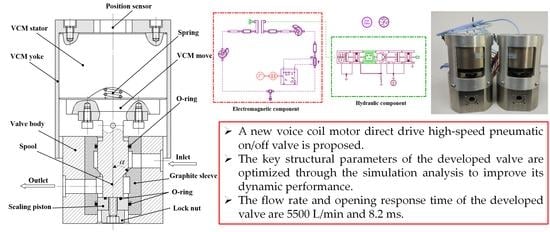
Beijing Key Laboratory of Advanced Manufacturing Technology, Beijing University of Technology, Beijing 100124, China
*
Author to whom correspondence should be addressed.
Appl. Sci. 2018, 8(4), 611; https://doi.org/10.3390/app8040611
Submission received: 12 February 2018 / Revised: 3 April 2018 / Accepted: 3 April 2018 / Published: 12 April 2018
(This article belongs to the Special Issue Power Transmission and Control in Power and Vehicle Machineries)

Abstract

:
The high-speed pneumatic on/off valve is one of the critical components in pneumatic systems, which has been widely investigated in the last decades. In this research, a new voice coil motor direct drive high-speed pneumatic on/off valve (VCM-DHPV) is proposed, and the mathematical model of VCM-DHPV, which consists of the fluid subsystem and electro-mechanical subsystem, is established. In addition, the key structural parameters of VCM-DHPV are optimized through the simulation analysis to improve its dynamic performance. The experiment results show that the developed VCM-DHPV has a good sealing performance by adopting the face-seal type in the valve port, and a large flow rate up to 5500 L/min, and its opening response time is 8.2 ms under the gas supply pressure of 8 MPa and exiting voltage of 240 V. With the supply pressure and the exciting voltage rising, the opening response time of VCM-DHPV is gradually increasing, and the variation tendency of the spool displacement curves is in accordance with the simulation results. This research will have significantly effects on raising the performance of the high-speed pneumatic on/off valve and the development of pneumatic precision motion control.

Graphical Abstract

1. Introduction

A pneumatic high-speed on/off valve working in high pressure is one of the critical components in high-pressure pneumatic systems, which has been widely used in many applications, such as aviation, aerospace, underwater tools, drilling platform, and air-powered vehicle [1,2,3,4,5]. Therefore, it has gained more attention and has been investigated widely in recent years. The opening or closing of a spool orifice can control the volume flow of conventional hydraulic control valves. Compared with servo or proportional valves having complex structures and high cost, a certain number of simple on/off valves, which are known as digital hydraulic valves, have advantages of easy digital control, low power loss and compact structure, and the volume flow is controlled by on/off fluid [6,7,8,9]. However, there are some challenging issues associated with the development of pneumatic high-speed on/off valve working in high pressure, which is mainly due to the frequency response and thrust demand of the driving elements.
Recently, the research on the high-speed on/off valves concentrates upon improving the dynamic performance of the high-speed electro-mechanical actuator, developing the new structural pilot high-speed on/off valve. It has been confirmed that the conventional driving elements such as solenoid, torque motor and piezoelectric transducer are difficult to meet the requirements of high frequency response, larger thrust and low cost of the direct drive high-speed on/off valves simultaneously [10,11,12]. Wang et al. [13] studied the control performance of two-stage pilot high-speed switching valve driven by high-speed solenoid. It is found that the control signal, the operating frequency of high-speed switching valve, and the control chamber pressure could directly affect the response time of the main stage. However, because of the limitations of the valve stroke and magnetic force, it is difficult to achieve high pressure and large flow simultaneously. Therefore, the high-speed switching valve driven by high-speed solenoid was used as pilot valve, and the rated pressure and rated flow of the developed pilot valve are 2 MPa and 2 L/min, respectively.
Due to the limitations of the pilot valve response time, it is hard to increase dynamic response performance of the main valves. Besides, the two-stage on/off valves also have some disadvantages, for example, the machine of the nozzle is difficult and easy to be polluted, and has a high energy losses through pilot stage. Consequently, the single stage valves driven by the linear electro-mechanical actuator directly is a research hotspot at present. Voice coil motor (VCM) characterized by its fast dynamic response, ease of control, good repeatability, large thrust and compact structure is employed to direct drive the spool of high-pressure hydraulic and pneumatic direct drive valves. Li et al. [14,15] numerically and experimentally investigated a high pressure pneumatic VCM direct drive servo valve. The hybrid control scheme consisting of the disturbance observer and the proportion integration differentiation (PID) controller was established, which includes the velocity/acceleration feed-forward. The experimental results showed that the improved spool position control system has a good disturbance rejection capability and strong robustness. Guo et al. [16] designed a new voice coil motor with high acceleration by the electromagnetic finite element method and the magnetic circuit method, and developed a high-frequency response VCM direct drive valve (DDV) system. Then, the VCM-DDV system adopted a nonlinear PID control strategy and a dual closed-loop control structure. The experimental results showed that the designed VCM has an evident improved acceleration, and the static and dynamic performances of the VCM-DDV system are excellent, whose position bandwidth can achieve 350 Hz. Wu et al. [17,18] researched the influence of current–force coefficient and damping length of the VCM on the performance of the hydraulic direct drive valve, and the design parameters of VCM were optimized. The results showed that certain types of VCMs might be more appropriate for application in DDVs. Miyajima et al. [19] presented a VCM direct drive pneumatic three-port spool type servo valve, which has a high natural frequency of 300 Hz and a small leakage through the annular gap between the spool and the sleeve when the inlet pressure was 0.6 MPa.
Although some works have been presented to study the DDVs driven by VCM, very little evidence has been found in development of high pressure pneumatic on/off valve driven by VCM. The objective of this research is to propose a novel pneumatic on/off valve with a high pressure, large flow rate and high dynamic response. In Section 2, the structure of newly developed on/off valve is introduced, and then the mathematical models of electro-mechanical and fluid subsystem for the on/off valve are described. The simulations for the dynamic response of the on/off valve in the AMESim (Siemens, Munich, Germany) are presented in Section 3. In Section 4, the static and dynamic performances of the on/off valve are experimentally investigated, and the results and discussion about the experiments and simulations are analyzed. Conclusions are provided in Section 5.

2. Characterization and Methodology

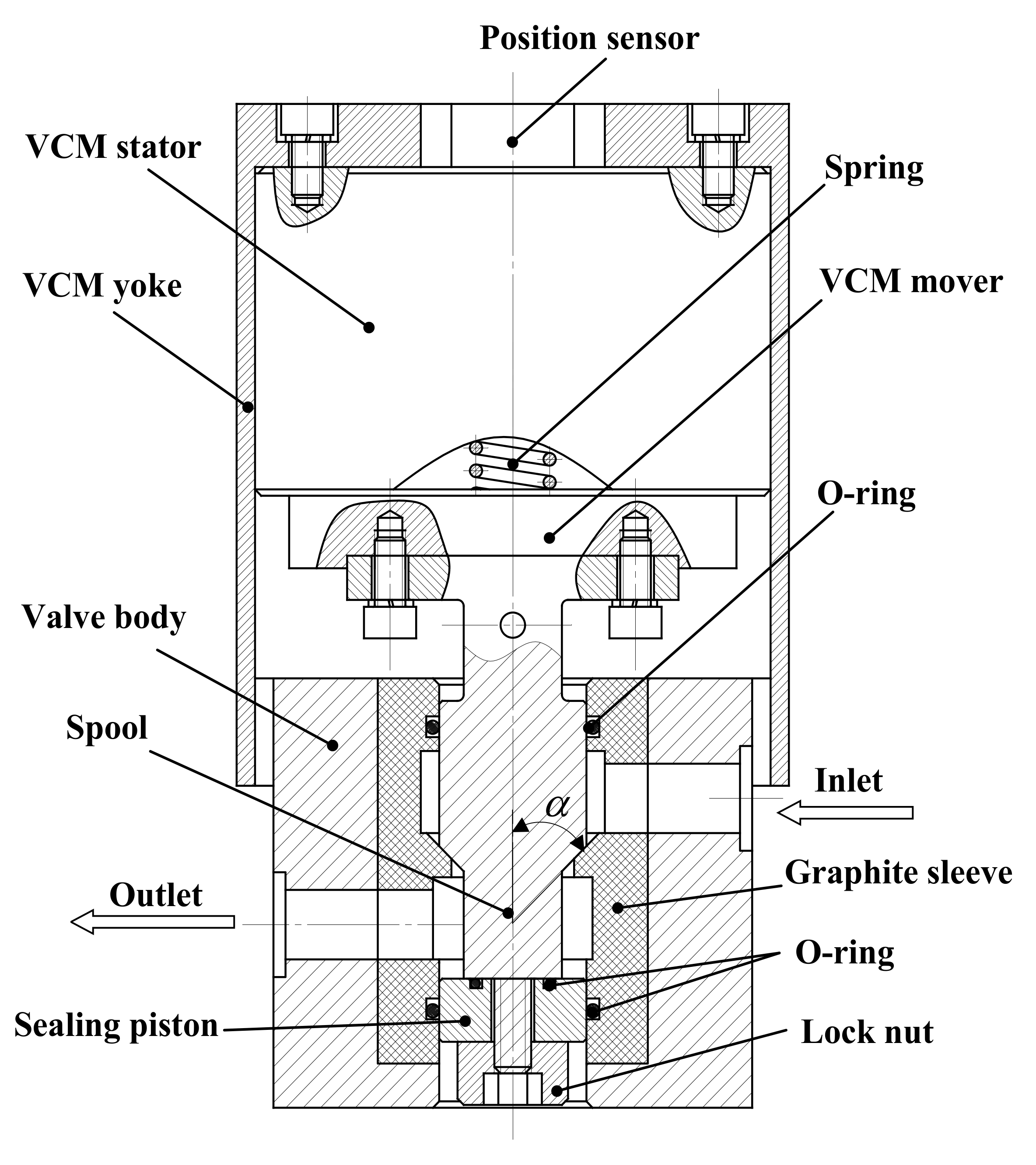
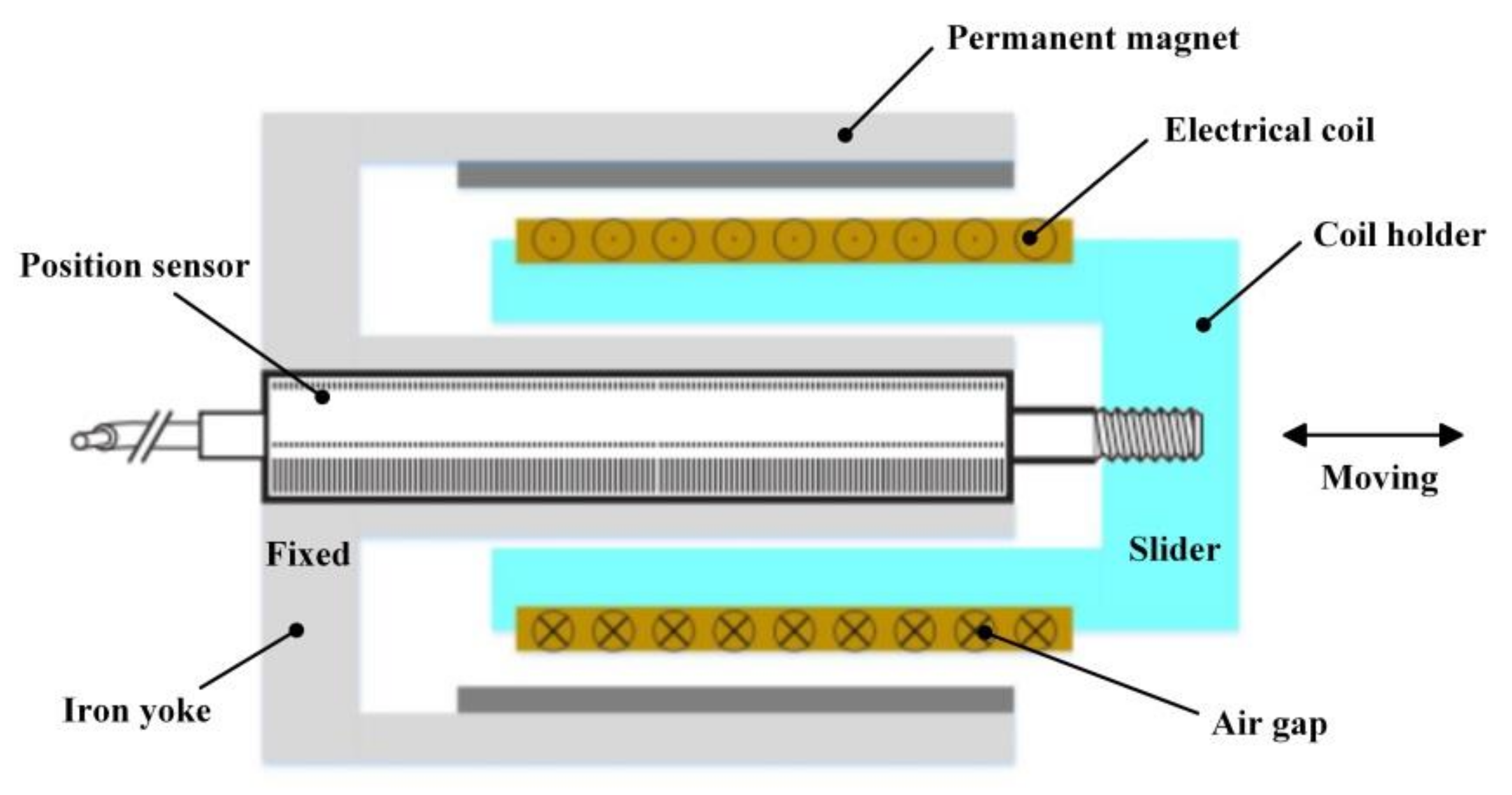
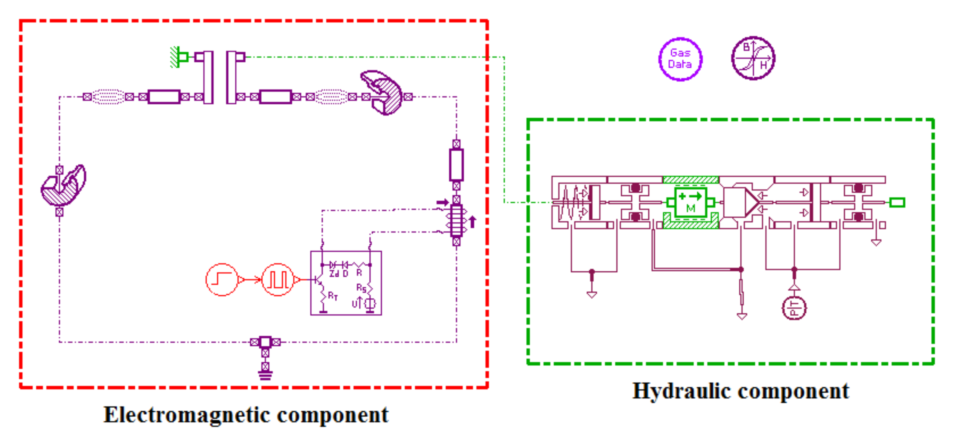
2.1. Description of VCM-DHPV

Figure 1 illustrates the schematic diagram of VCM-DHPV, which consists of two parts: the pneumatic on/off valve and the VCM actuator. The on/off valve is regarded as an electro-pneumatic converter, which has the functions of the power amplified element and the energy conversion [20]. The VCM actuator proposed is shown in Figure 2. The main part of the VCM is composed of an iron yoke and a cylindrical permanent magnet, which can make a radially-oriented magnetic field in the air gap of the VCM. The moving part of the VCM is composed of the plastic bobbin and the wire winding, which can provide an Ampere force in the vertical direction perpendicular to the current flow and the magnetic flux when the coil is energized [21]. The spool connected directly with the slider is driven linearly by the VCM actuator. The permanent magnet of actuator is fixed with the valve body as the stator. To eliminate the excess pneumatic force acting on the spool, the lock nut is designed to balance the area difference of the spool, and then only the flow force and seal friction should be overcome by VCM. Therefore, the electromagnetic force of VCM is decreased and the dynamic characteristic of VCM-DHPV is improved. A high-accuracy position sensor mounted on the VCM is used to measure the displacement of the valve spool, and the position signal is fed back to the system controller, which generates the coil current. The poppet valve face-seal type is used in the valve port to reduce the leakage of VCM-DHPV when working under high-pressure condition. In addition, the face-seal in the valve port is made of graphite sleeve dipped with the phenolic resin, so the graphite valve port is softer than the valve cone made of ceramic, which is sprayed at the surface of titanium alloy spool. This kind of soft–hard contact sealing can archive zero leakage of the valve port. As a control component, the VCM-DHPV is designed to control gas flows through the pipelines and the chambers in the pneumatic actuator. Therefore, based on the position control system, the displacement of the valve spool is regulated accurately, so that it can control the gas quickly through the valve port from inlet to outlet.
When there is no exciting voltage signal, the spool is compressed tightly on the graphite sleeve by the spring, and then the VCM-DHPV is closed. As positive exciting voltage signal is given, the spool moves upward under the action of the electromagnetic force by VCM, and then the valve is opened. As a result, the inlet port and outlet port are interlinked. The high-pressure air flows from the inlet port into atmosphere through the outlet port. As negative exciting voltage signal is given, the spool moves downward under the action of the electromagnetic force by VCM, and then the VCM-DHPV is closed, and the inlet port and outlet port are disconnected.
The dynamic characteristic of VCM-DHPV is one of the main research focuses. According to ISO 5598-2008, the dynamic response time of fluid power components can be described as the elapsed time between the action initiation and the resulting reaction, which is tested under stated conditions. In this research, the opening response time is considered as the elapsed time between the initiation point when the exciting voltage is given and the point when the on/off valve is fully opened.

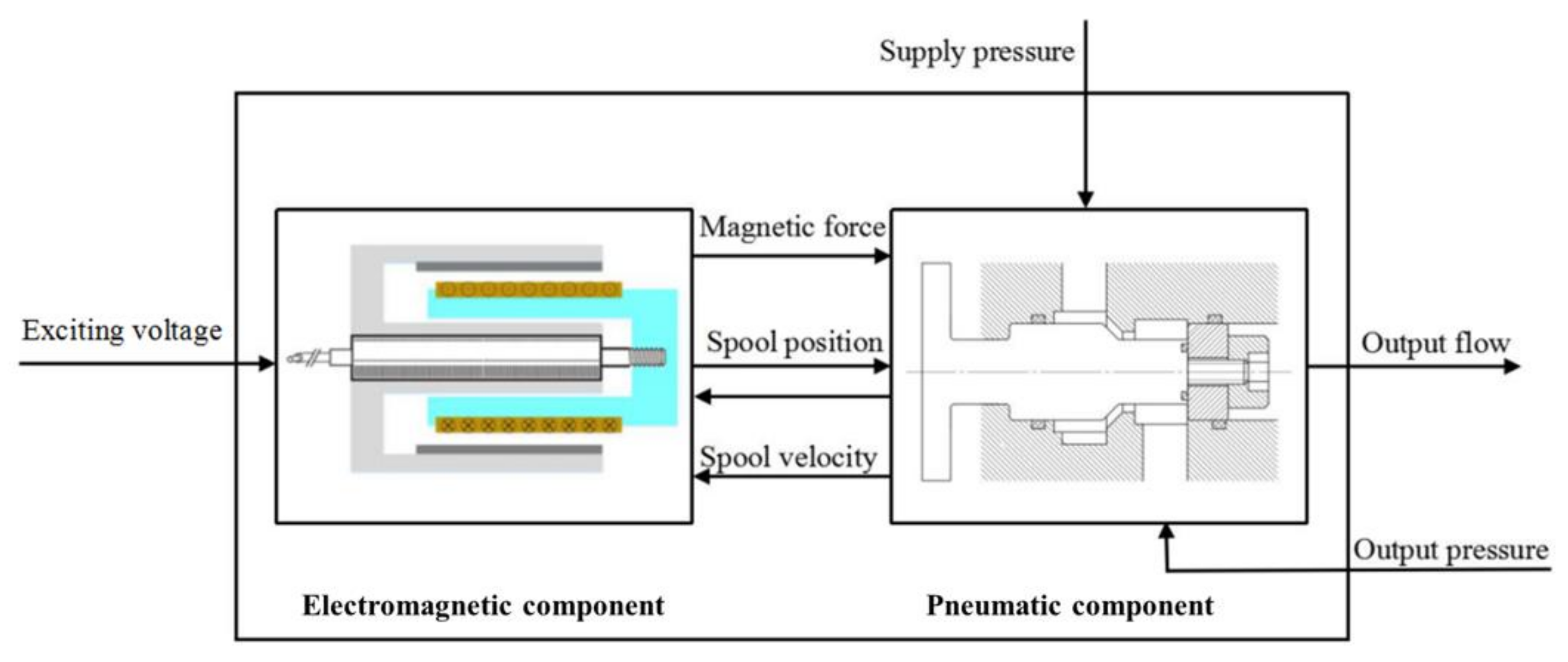
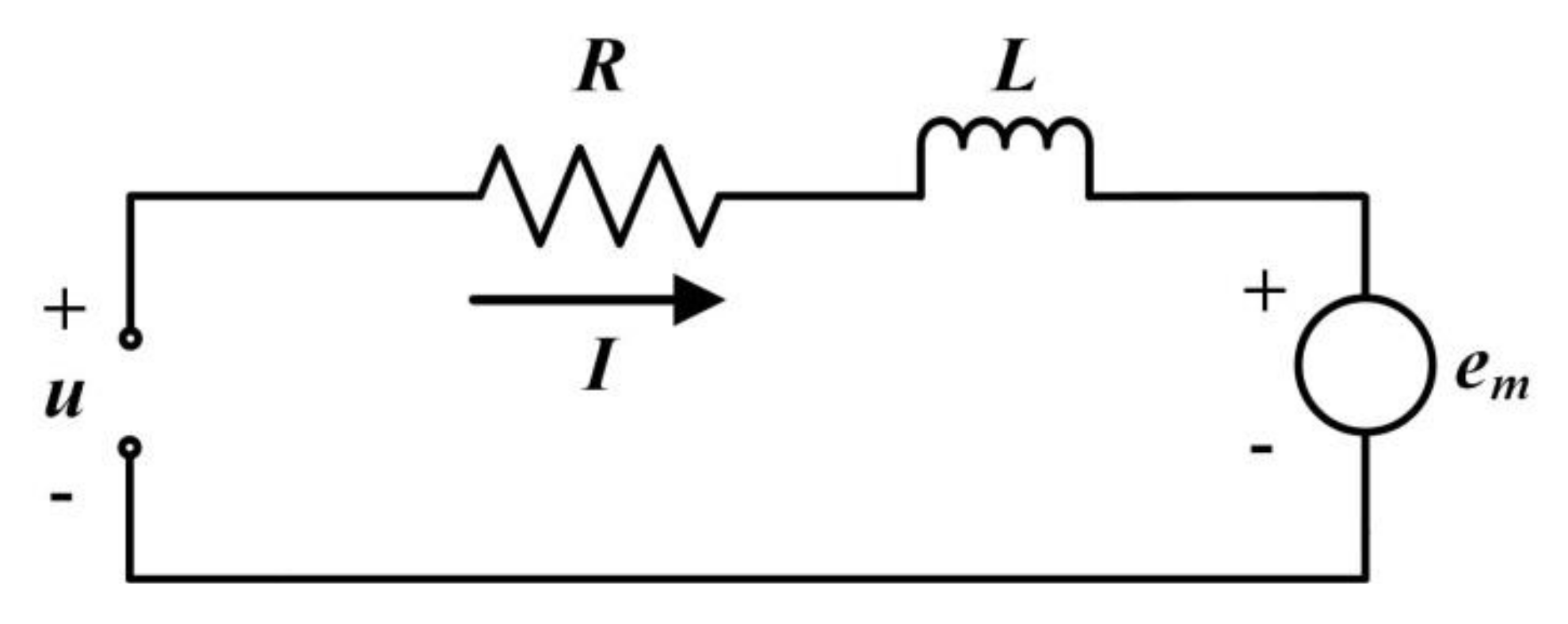
2.2. Mathematical Model

As a pneumatic control component, the on/off valve was designed to provide rapid gas-flow through the cavities inside the pneumatic actuator. The characteristics of the on/off valve depends on the flow and electro-mechanical equations, whose relationships are intensively coupled with each other. Therefore, the on/off valve can be regarded as a converter between the electric and the pneumatic. Figure 3 describes the block diagram of VCM-DHPV, which illustrates the signal flow of the on/off valve model from the input voltage of the VCM to the output flow of the valve, including the intermediate interactions. As shown in Figure 3, the VCM-DHPV can be divided into pneumatic component and electromagnetic component. Then, the characteristic equations of VCM-DHPV could be obtained.
In the single degree of freedom (DOF) mass–spring–damper system for the moving part of VCM-DHPV, which consists of the VCM mover and the spool, Newton’s second law of motion is given by:
m d 2 x ( t ) d t 2 + b d x ( t ) d t + k s ( x ( t ) + x 0 ) + F s + F f + F t = F e
where x(t) is the displacement of the VCM mover and the spool (mm), m is the mass of the coil of VCM and spool of the on/off valve assembly (kg), b is damping coefficient (N/(m/s)), ks is spring constant (N/m), x0 is spring pre-tension (mm), Fs is steady gas flow force (N), Ff is Coulomb’s friction force (N), Ft is transient gas flow force (N), Fe is electromagnetic force of the VCM (N), and Ff is Coulomb’s friction force (N), which is very small compared to the electromagnetic force and can be ignored. Because the friction force and gas flow force are uncertainty, nonlinearity and time variation, the forces Fs and Ft can be considered as the disturbances for the valve spool position control system of VCM-DHPV [15], which will be presented as follows.
The electromagnetic component consists of a magnetic circuit and an electrical circuit [16]. According to the Lorentz force principle, the electro-mechanical conversion of the voice coil motor can be obtained. Therefore, the electromagnetic force of VCM is expressed as:
F e = K e i = B l N i
where Ke is current–force coefficient, so Fe is proportional to the current of the coil.
Figure 4 depicts the equivalent circuit of the voice coil motor, and its voltage balance equation can be written as:
R i + L s d i d t + e m = u
where R is resistance of the coil, Ls is inductance of the coil, and em is back EMF, which can be expressed as:
e m = B l N d x d t = K e d x d t
The air-flow is a complex thermodynamic process, where it is a variable mass system in VCM-DHPV. According to the energy equation, continuity equation and dynamic equation, the mathematical model of the air-flow can be established. It should be noted that the gas supply pressure of the developed VCM-DHPV varies in the range of 0.1–8 MPa. As the pressure of the air is less than 20 MPa, the gas compressibility factor has little deviation from 1% (less than 5%), therefore the high-pressure air could be simplified to the ideal gas [14,15,22]. Because the start up process of VCM-DHPV is very short, the exhaust process of the control chamber can be simplified to an adiabatic process. The following assumptions are given as follows [23]:
  • A constant stable gas supply is considered.
  • Flowing process of gas through valve port of VCM-DHPV is isentropic.
  • The pressure and thermal fields are uniformly distributed inside every cavity of VCM-DHPV.
  • The spring of VCM-DHPV is assumed to be linear. In addition, the masses of spool, piston, and spring are integrated into one inertial parameter.
  • Dynamic flow forces, gas inertia and pressure loss in tubes can be neglected.
  • Steady state flow forces are considered only.
The electromagnetic component can be used to control gas flow through adjusting spool position of the on/off valve. For turbulent flow, the spool orifice equation can be used to represent the gas flow through VCM-DHPV, which includes the subsonic and choked flow regimes. Because the high-pressure air in pneumatic components and pneumatic system is compressible, as the ratio of the upstream pressure pu to the downstream pressure pd is larger than the critical value σcr, the flow regime can be regarded subsonic and the mass flow depends nonlinearly on both pressures. However, when the ratio is smaller than the critical value σcr, the flow achieves sonic velocity (choked flow) and depends linearly on the upstream pressure pu [8,22]. In these two cases, the air mass flow depends linearly on the spool position of the on/off valve. The standard equation for the mass flow rate through the spool orifice can be modeled as:
m ˙ t = α S p u k R T ϕ ( p u , p d )
where α is the coefficient of contraction, S is the passage area of the spool orifice, S = 4CdDx(t), Cd is discharge coefficient, D is the orifice diameter of the valve, x(t) is opening of the on/off valve, k is specific heat ratio of air, R is gas constant of air, and T is absolute temperature. φ(pu,pd) is given by [24,25]:
ϕ ( p u , p d ) = { ( 2 k + 1 ) k + 1 k 1 w h e n ( p d p u σ c r ) 2 k 1 ( ( p d p u ) 2 k ( p d p u ) k + 1 k ) w h e n ( p d p u > σ c r )
where σcr is critical pressure ratio, which is equal to 0.5283 and can be defined as:
σ c r = ( 2 k + 1 ) k k 1
Based on the momentum conservation principle, the steady gas flow force on valve spool can be calculated as:
F s = m ˙ t ( x ( t ) ) v cos θ
Besides, the transient gas flow force acting on the valve spool can be written by:
F t = ± L v d m ˙ t d t = ± L v α d S d t p u k R T ϕ ( p u , p d ) = ± 4 L v α C d D p u k R T ϕ ( p u , p d ) d x ( t ) d t
where Lv is damping length of the on/off valve, θ is gas flow jet angle, and v is gas flow velocity.
Therefore, after adopting the Laplace transform for Equations (1) and (3) under the boundary condition X(0) = 0 and the initial condition X’(0) = 0, they can be represented as follows:
m s 2 X ( s ) + b s X ( s ) + k s X ( s ) + F f + F t + F s = K e I ( s )
( R + L s ) I ( s ) + K e s X ( s ) = U ( s )
Consequently, with Equations (10) and (11), the transfer function between the X(s) and the U(s) for the on/off valve driven by the VCM directly can be derived as:
G p ( s ) = X ( s ) U ( s ) = K e / ( R + L s ) m s 2 + [ K e 2 / ( R + L s ) + b ] s + k s

3. Simulation Analysis

The start up process of VCM-DHPV, which has nonlinear relation to the displacement of on/off valve spool in the case of the constant inlet pressure, is not constant stable. It is very difficult to calculate the mathematical model of pressure. To determine the dynamic and static characteristics of VCM-DHPV, the equations of the mathematical model could be solved numerically by the AMESim software, in which the relationship between supply pressure Ps and x could be expressed numerically. The simulation diagram was established by AMESim, as shown in Figure 5. A physical diagram was made in AMESim based on the mathematical model. The design parameters of VCM-DHPV are shown in Table 1. Then, the dynamic response curves of VCM-DHPV under different exciting voltage u, supply pressures Ps and half cone angle α of the spool (as illustrated in Figure 1) can be obtained through the simulation, as shown in Figure 6, Figure 7 and Figure 8.

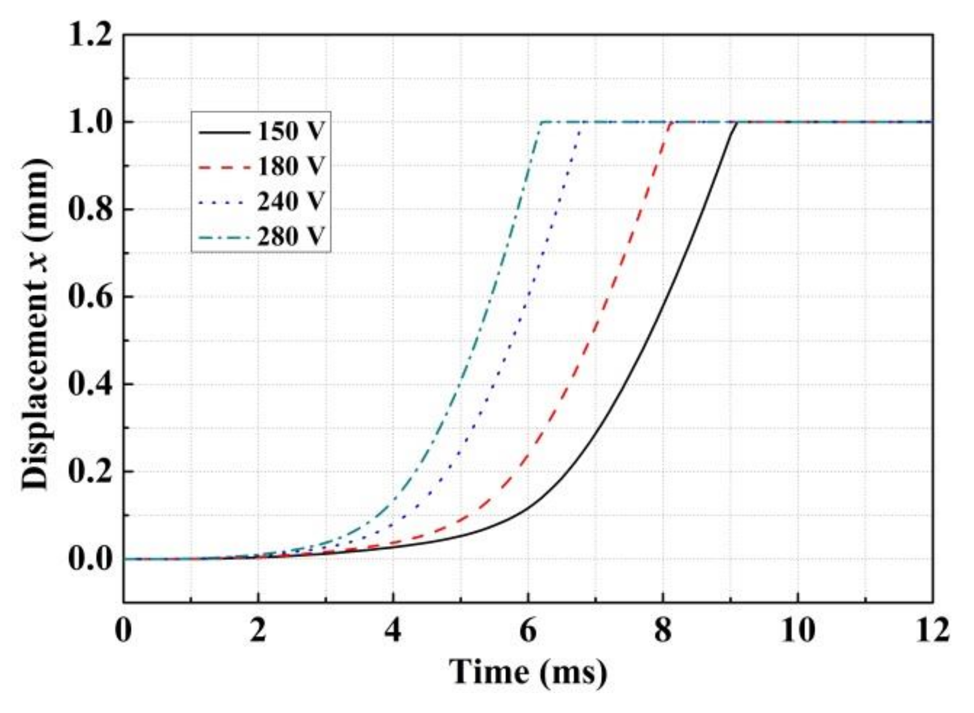
3.1. Influence of the Exciting Voltage

To investigate the sensitivity of dynamic response characteristic of VCM-DHPV to the different exciting voltage, the simulations are performed at the exciting voltage of 150, 180, 240 and 280 V (with the supply pressure of 8 MPa). It can be seen in Figure 6 that the opening response time of VCM-DHPV decreases while the exciting voltage u gets bigger. This is because the bigger exciting voltage of the VCM coil could rapidly increase the current. Thus, the opening response time of the VCM becomes shorter. The opening response times of the on/off valve at the exciting voltage u of 150, 180, 240 and 280 V are 9.1, 8.2, 6.8 and 6.2 ms, respectively. Therefore, from the increase of the dynamic characteristic purpose point of view, the exciting voltage should be appropriately improved during the process of switching for VCM-DHPV.

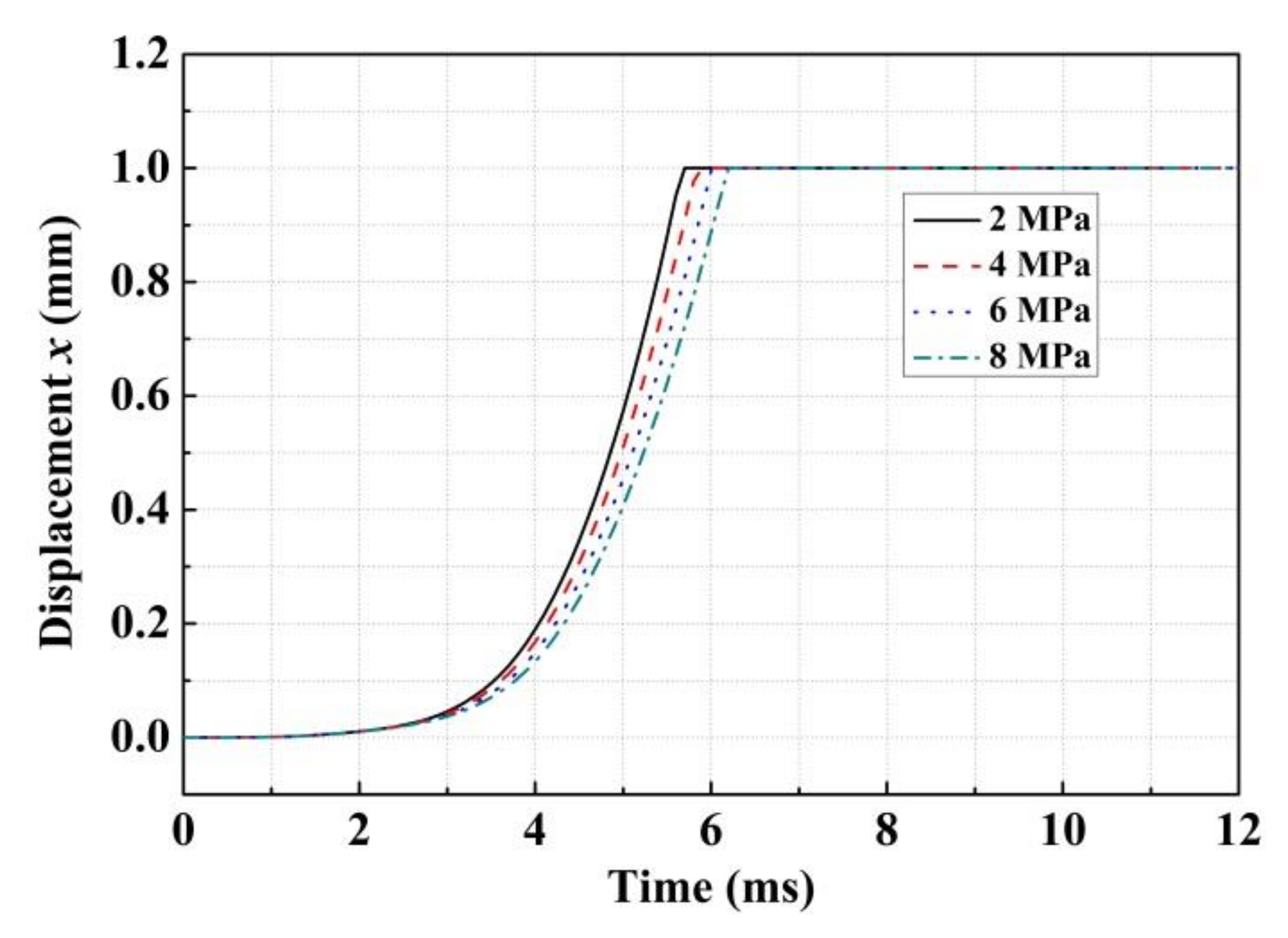
3.2. Influence of the Supply Pressure

Because the maximum working pressure of the developed VCM-DHPV is 8 MPa, the numerical simulation was conducted under different supply pressures which are less than 8 MPa (2, 4, 6 and 8 MPa) to investigate its dynamic characteristics. Figure 7 illustrates the displacement of spool versus simulation time of VCM-DHPV under different supply pressures (with the exciting voltage of 240 V). When only the supply pressure of VCM-DHPV is changed in the simulation, it can be seen in Figure 7 that the opening response time increased with the rise of the supply pressure. Here, the opening response times are 5.7, 5.9, 6.1 and 6.2 ms under the supply pressures of 2, 4, 6 and 8 MPa, respectively. This is attributed to the fact that the transient and steady gas flow forces gradually increased with the rise of supply pressure.

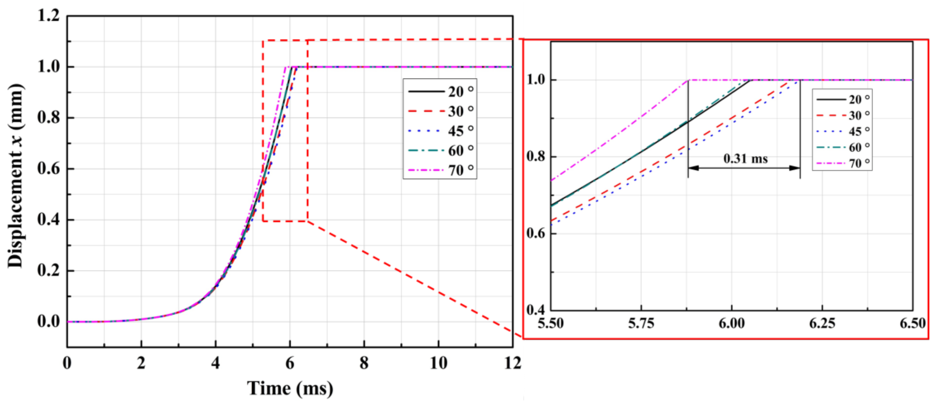
3.3. Influence of the Half Cone Angle

Based on Equations (5) and (6), the key structural parameters of the on/off valve would also affect the dynamic response characteristics. Taking the half cone angle α of on/off valve spool as an example, when changing the value of the half cone angle α from 20° to 70° (u = 240 V and Ps = 8 MPa), it is achieved in Figure 8 that the bigger half cone angle α could slightly increase the opening response time of VCM-DHPV. The explanation of this is that as the half cone angle of the spool enlarged, the transient and steady gas flow forces would be gradually increased. However, it is also shown in Figure 8 that the maximum difference of VCM-DHPV opening response time under different half cone angle is very small (0.31 ms). This indicated that increasing the half cone angle cannot effectively improve the dynamic response of VCM-DHPV. In addition, the 45° angle is convenient for manufacturing and obtaining an appropriate sealing ability. Therefore, the half cone angle of 45° should be applied to the design of VCM-DHPV prototype.

4. Experiment Verification

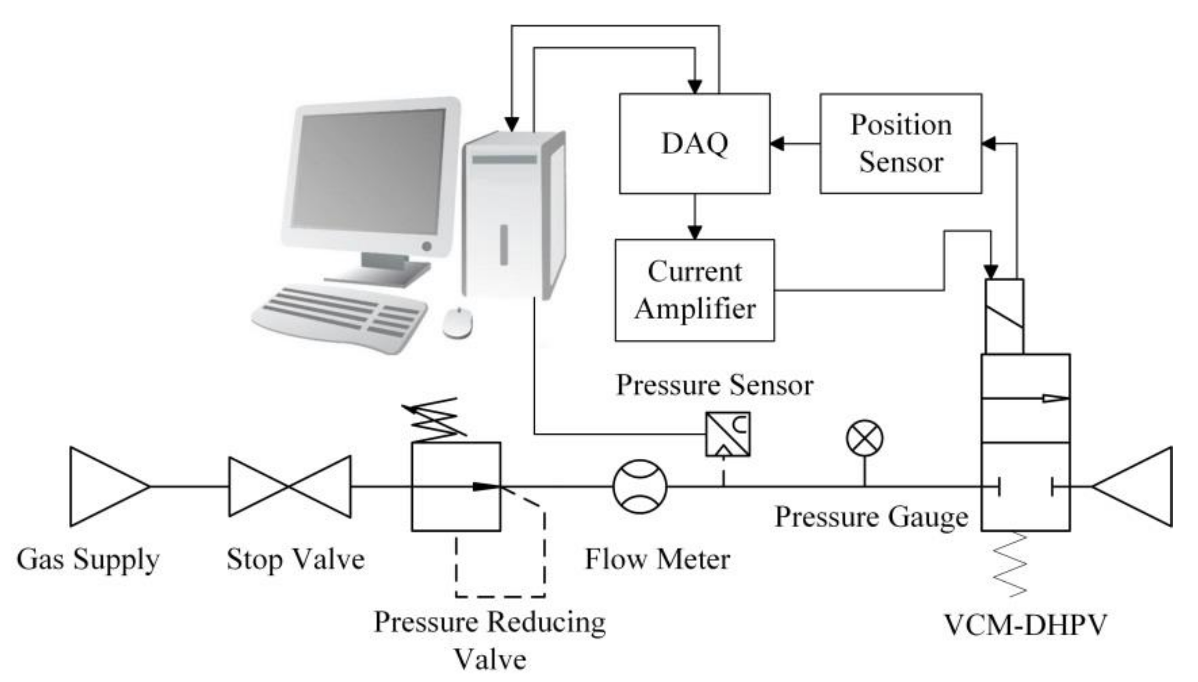
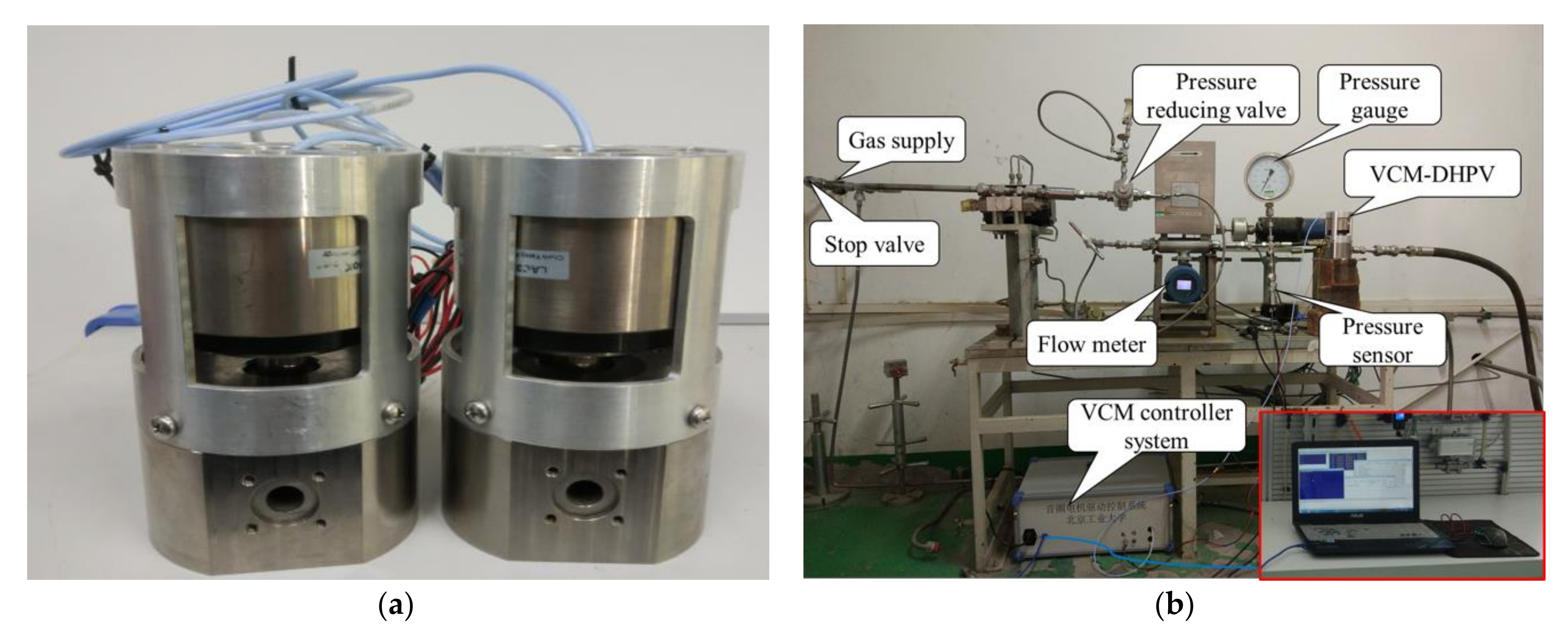
4.1. Experiment Apparatus

To verify the feasibility of VCM-DHPV structure and the validity of the mathematical model, the experimental investigation was carried out. Experimental pneumatic circuit is shown in Figure 9, which is composed of a gas supply, stop valve, pressure reducing valve, flow meter, pressure sensor, pressure gauge, the on/off valve, current amplifier, position sensor, data acquisition (DAQ) and the controller. The control scheme of the on/off valve is realized by a programmable multi-axis controller (PMAC). The VCM and the position sensor were linked to a personal computer with Pewin32 Pro2 software through a DAQ, which was used to acquire position signal and control the input voltage of the VCM [26]. The rated current and rated force of the VCM used in this experiment are 8.4 A and 376 N, respectively. Therefore, a current amplifier could be adopted to amplify the current and supply to VCM. The voltage command is supplied from the computer through the DAQ, and the output voltages from the position sensor are fed back to the computer by the DAQ. Then, the spool of VCM-DHPV is actuated toward two directions. The test software is developed on the LabVIEW platform (version 11.0, National Instruments, Austin, TX, USA, 2011).
A linear variable differential transformer (LVDT) is used to detect the displacement of spool, which is transferred by a push rod connected with the spool. When the spool is promoted, it will push the rod detected by the position sensor. The developed VCM-DHPV prototype and the test bench are shown in Figure 10, and the characteristic parameters of the prototype are listed in Table 2. The experiment processes are as follows:
  • Open the stop valve and regulate the pressure reducing valve to make the compressed air as a certain pressure.
  • Use the computer to collect the pressure signal, flow signal and displacement signal when opening the on/off valve.
  • Set a new pressure and repeat Steps (1) and (2).

4.2. Experiment Results and Discussion

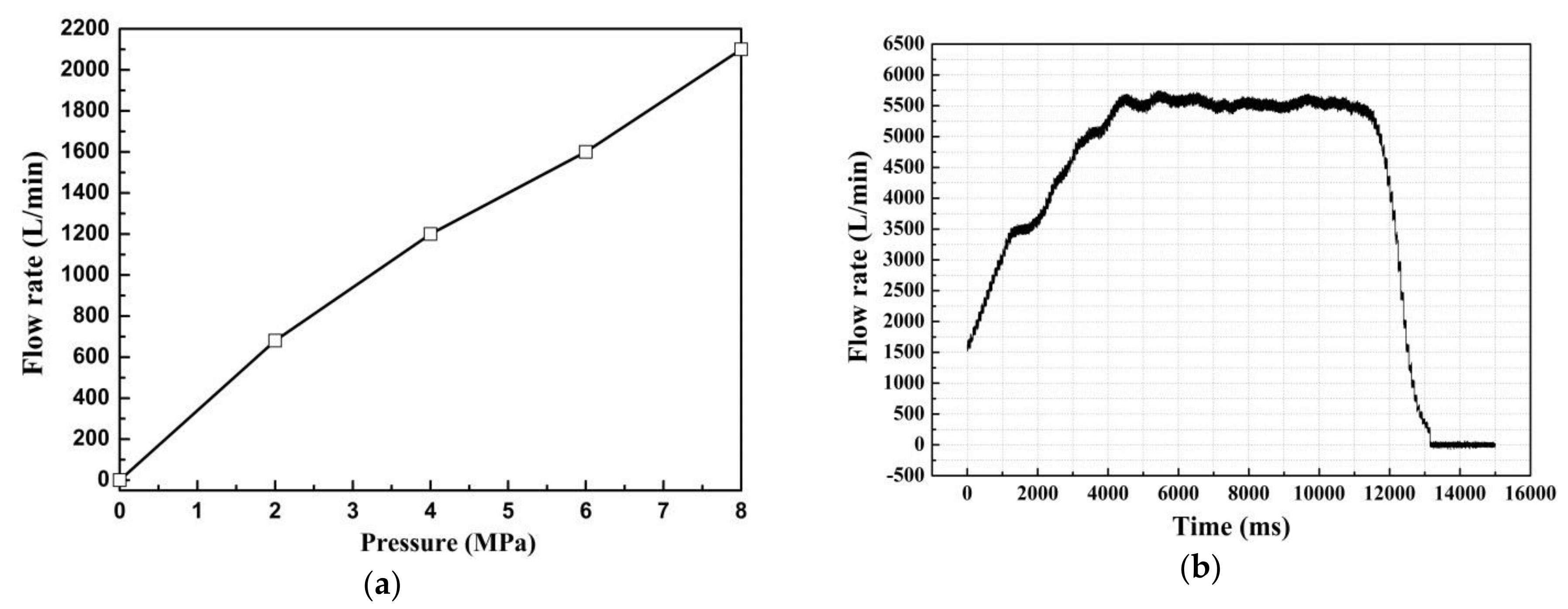
4.2.1. Static Characteristics Experiments

To verify the sealing and flow characteristics of VCM-DHPV, the static characteristics of the valve is examined. Firstly, VCM-DHPV is closed by the VCM reverse power, and the supply pressures of the valve are set to 2, 4, 6 and 8 MPa, respectively. Then, the pressure sealing performance of the on/off valve is checked under the pressure holding time of 2 min. The experimental results show that the pressure sealing performances of VCM-DHPV are very good under the different supply pressures. The flow rate of VCM-DHPV under different supply pressures and is illustrated in Figure 11a. It can be seen that, with the gradual increase of supply pressure, the flow begins to increase rapidly. As the supply pressure continues to be increased to a certain value, the flow rate of VCM-DHPV could reach a stable value of about 5500 L/min, as shown in Figure 11b.

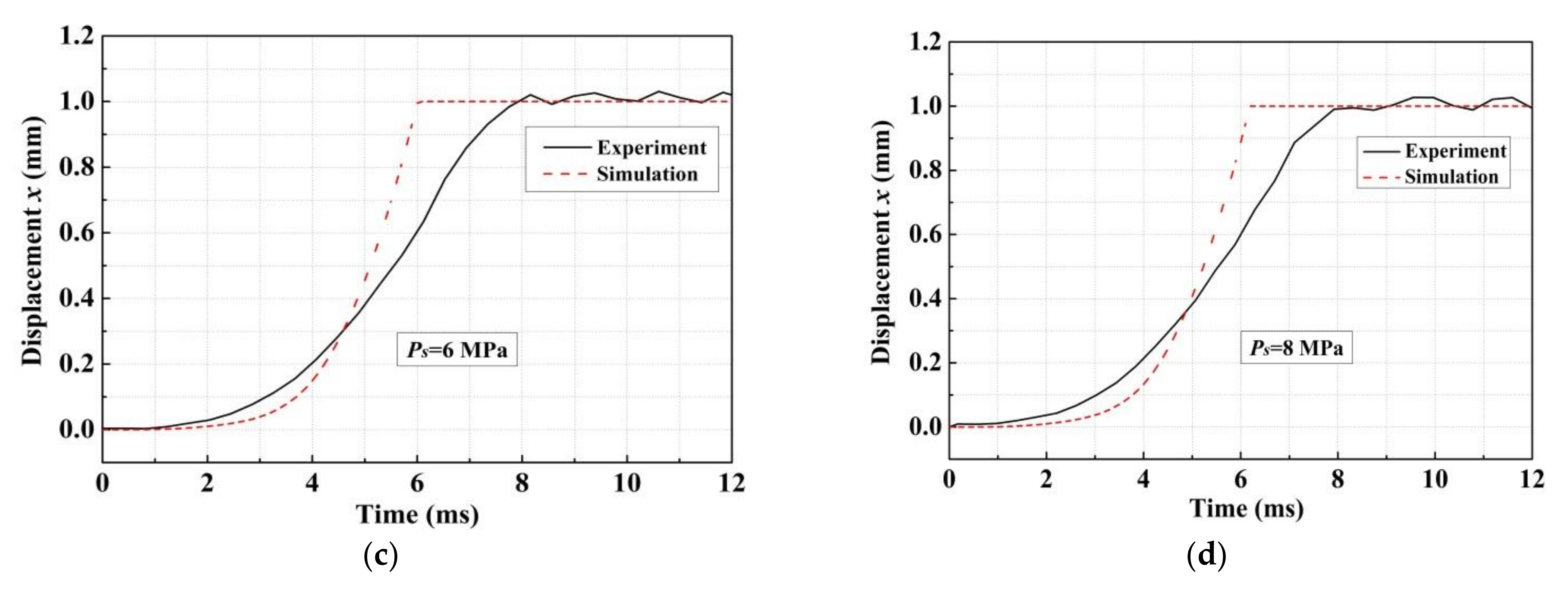
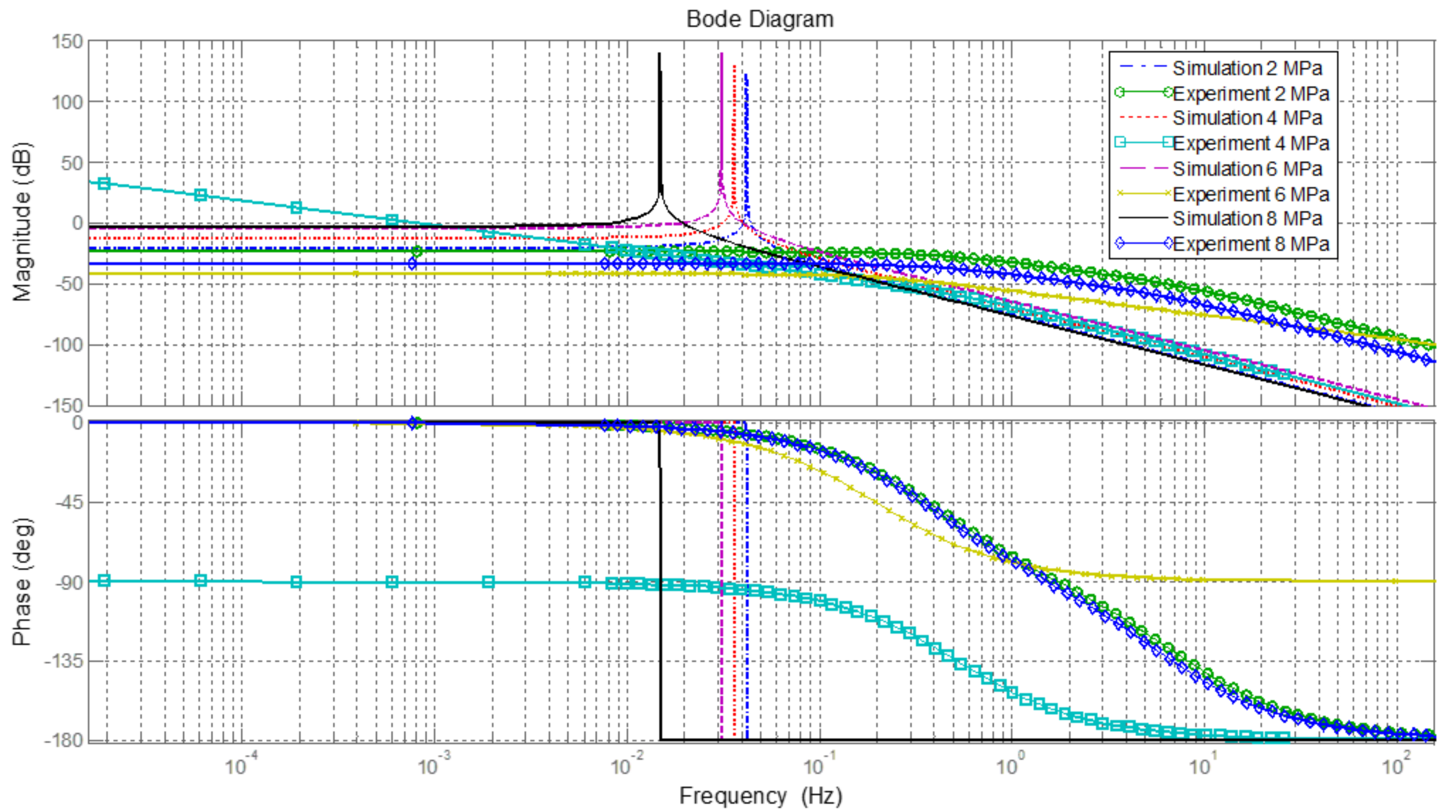
4.2.2. Dynamic Characteristics Experiments

The dynamic characteristics experiment is conducted to obtain the displacement of spool versus test time of VCM-DHPV under different supply pressures. Figure 12 shows the comparisons of the step response between the simulation results and measurements of the developed VCM-DHPV under different supple pressures. The red dashed lines stand for simulation results and the black solid lines stand for experimental results. It can be seen in Figure 12 that the curve of the simulations changes along with the trend of the experimental results, so the comparisons between the simulation results and measurements resulted in an acceptable agreement. However, as presented in Figure 12, due to the uncertainties of the sensors, some small overshoots can be observed. The opening response times of the on/off valve under different supply pressures by the simulation and experiment are listed in Table 3.
As presented in Table 3, the deviation of the simulated and measured response time under the supply pressures of 2, 4, 6 and 8 MPa is about 1.6, 1.5, 1.8 and 2.0 ms, respectively, and the deviations increase with the increasing supply pressures. This is because the friction force between the valve core and the valve body increases with the increasing supply pressure in the experiment, leading to the long response time of VCM-DHPV. However, the friction force is neglected in the numerical simulation. As a result, the deviations between the simulation and experiment increase with the increasing supply pressure. These results show that the simulated results provided a reasonable agreement within neglect of uncertainties of the sensors and the friction force between the valve core and the valve body. Therefore, it can be concluded that the numerical simulation and experimental results show the same change tendency and the presented AMESim model is acceptable in analyzing the dynamic characteristics of VCM-DHPV.
Meanwhile, the system identification tools in MATLAB (MathWorks, Natick, MA, USA) are employed to identify the system parameters of the developed VCM-DHPV by the simulation and experiment. The transfer function of on/off valve is acquired, and then the dynamic characteristics of the on/off valve via the frequency responses with the full stroke can be drawn in MATLAB. Figure 13 shows the Bode diagram of VCM-DHPV through the simulation and experiment under different supply pressures. The results show that the transfer function of the on/off valve could be simplified to be a second-order oscillating system. Because the damping ratio in the transfer function of the on/off valve are not considered in the simulation (ζ = 0), the bandwidth of the on/off valve is significantly influenced by the supply pressure, and its amplitude frequency characteristics of the simulations have an obvious pulse. However, due to the friction force and hydraulic leakage, the damping ratio could not be equal to zero in the actual working condition. It is worth noting in Figure 13 that the frequency responses of the on/off valve are quite different when the supply pressures are set as 2.0, 4.0, 6.0 and 8.0 MPa, respectively. Besides, it is illustrated in Figure 13 that the gain margin GM and phase margin PM of VCM-DHPV are both greater than zero. As a result, it can be concluded that VCM-DHPV is a stable minimum-phase system.
In addition, it can be seen in Figure 13 that the frequency responses of the simulations and experiments are not identical, and there is a large delay. This is attributed to the delay effect of the position sensor fixed on the spool in experiment process and the friction forces of the two O type rings ignored in the simulation model. Actually, the delay time of position sensor and friction force could disturb the dynamic characteristics of on/off valve in the experiment process, which would affect the push–pull effort of the VCM and cause the dynamic response time slowing. Consequently, further improvement of VCM-DHPV dynamic characteristics by upgrading the accuracy of position sensor and reducing the friction force between valve core and valve sleeve will be the main research concerns in the future.

5. Conclusions

In this research, a new high-pressure large-flow pneumatic on/off valve driven directly by the voice coil motor is presented. The structure and working principle are quite different from the traditional two-stage on/off valve. The mathematical model and transfer function are derived in detail to analyze its response characteristics. The simulation results based on AMESim software show that the exciting voltage, half cone angle and supply pressure could influence the response time of the on/off valve significantly. The opening response time of the developed valve is decreased with the exciting voltage, whereas increased with the supply pressure. Besides, the half cone angle has been optimized to get the shorter opening response time. Then, an experiment is carried out to verify the feasibility of novel structure and validity of the numerical simulation, which shows that the flow rate and opening response time of the on/off valve are 5500 L/min and 8.2 ms under the gas supply pressure of 8 MPa and exiting voltage of 240 V. The experimental results indicate a reasonable match between the simulations and measurements, and both simulation analysis and experimental results exhibit that the on/off valve satisfies the initial design requirements well.

Acknowledgments

The authors would like to thank the National Natural Science Foundation of China (Grant Nos. 51705008 and 11572012), Beijing Natural Science Foundation (Grant Nos. 3182003, 1184012 and 3164039), Beijing Municipal Science and Technology Project (Grant No. KM201810005014), China Postdoctoral Science Foundation funded project (Grant No. 2017M620551) and Beijing Postdoctoral Research Foundation (Grant No. 2017-ZZ020) for their funding for this research. The authors are very grateful to the editors and the anonymous reviewers for their insightful comments and suggestions.

Author Contributions

Songlin Nie and Xiangyang Liu proposed the idea of the high-pressure pneumatic on/off valve direct-driven by voice coil motor for the purpose of increasing the frequency response; Xiangyang Liu and Fanglong Yin conceived and designed the experiments; Songlin Nie and Hui Ji contributed to the mathematical model; Fanglong Yin and Jingxiu Zhang performed the experiments and analyzed the data; Fanglong Yin wrote the Matlab code, established the AMEsim simulation model and conducted the numerical simulations; and Xiangyang Liu wrote the paper.

Conflicts of Interest

The authors declare no conflict of interest.

References

  1. Yang, H.; Pan, M. Engineering research in fluid power: A review. J. Zhejiang Univ. Sci. A 2015, 16, 427–442. [Google Scholar] [CrossRef]
  2. Simic, M.; Herakovic, N. Reduction of the flow forces in a small hydraulic seat valve as alternative approach to improve the valve characteristics. Energy Convers. Manag. 2015, 89, 708–718. [Google Scholar] [CrossRef]
  3. Richer, E.; Hurmuzlu, Y. A High Performance Pneumatic Force Actuator System: Part 1—Nonlinear Mathematical Model. J. Dyn. Syst. Meas. Control 2000, 122, 416–425. [Google Scholar] [CrossRef]
  4. Shi, Y.; Wang, Y.; Cai, M.; Zhang, B.; Zhu, J. Study on the Aviation Oxygen Supply System Based on a Mechanical Ventilation Model. Chin. J. Aeronaut. 2018, 31, 197–204. [Google Scholar] [CrossRef]
  5. Ren, S.; Cai, M.L.; Shi, Y.; Xu, W.Q.; Zhang, X.D. Influence of bronchial diameter change on the airflow dynamics based on a pressure-controlled ventilation system. Int. J. Numer. Methods Biomed. Eng. 2018, 34, e2929. [Google Scholar] [CrossRef] [PubMed]
  6. Taghizadeh, M.; Ghaffari, A.; Najafi, F. Modeling and identification of a solenoid valve for PWM control applications. C. R. Mac. 2009, 337, 131–140. [Google Scholar] [CrossRef]
  7. Heikkil, M.; Linjama, M. Displacement control of a mobile crane using a digital hydraulic power management system. Mechatronics 2013, 23, 452–461. [Google Scholar] [CrossRef]
  8. Topcu, E.E.; Ibrahim, Y.; Kamis, Z. Development of electro-pneumatic fast switching valve and investigation of its characteristics. Mechatronics 2006, 16, 365–378. [Google Scholar] [CrossRef]
  9. Shi, Y.; Zhang, B.L.; Cai, M.L.; Xu, W.Q. Coupling Effect of double lungs on a VCV ventilator with automatic secretion clearance function. IEEE/ACM Trans. Comput. Biol. Bioinform. 2017, 99, 1. [Google Scholar] [CrossRef] [PubMed]
  10. Kamelreiter, M.; Kemmetmüller, W.; Kugi, A. Digitally controlled electrorheological valves and their application in vehicle dampers. Mechatronics 2012, 22, 629–638. [Google Scholar] [CrossRef]
  11. Lee, G.S.; Sung, H.J.; Kim, H.C. Multiphysics analysis of a linear control solenoid valve. J. Fluid Eng. 2013, 135, 011104. [Google Scholar] [CrossRef]
  12. Ahn, K.; Yokota, S. Intelligent switching control of pneumatic actuator using on/off solenoid valves. Mechatronics 2005, 15, 683–702. [Google Scholar] [CrossRef]
  13. Wang, S.; Zhang, B.; Zhong, Q. Study on control performance of pilot high-speed switching valve. Adv. Mech. Eng. 2017, 9, 1–8. [Google Scholar] [CrossRef]
  14. Li, B.R.; Gao, L.L.; Yang, G. Modeling and control of a novel high-pressure pneumatic servo valve direct-driven by voice coil motor. J. Dyn. Syst. 2013, 135, 014507. [Google Scholar]
  15. Li, B.R.; Gao, L.L.; Yang, G. Evaluation and compensation of steady gas flow force on the high-pressure electro-pneumatic servo valve direct-driven by voice coil motor. Energy Convers. Manag. 2013, 67, 92–102. [Google Scholar] [CrossRef]
  16. Guo, H.; Wang, D.Y.; Xu, J.Q. Research on a high-frequency response direct drive valve system based on voice coil motor. IEEE Trans. Power Electron. 2013, 28, 2483–2492. [Google Scholar] [CrossRef]
  17. Wu, S.; Jiao, Z.X.; Yan, L.; Zhang, R.; Yu, J.T.; Chen, C.Y. A fault-tolerant triple-redundant voice coil motor for direct drive valves: Design, optimization, and experiment. Chin. J. Aeronaut. 2013, 26, 1071–1079. [Google Scholar] [CrossRef]
  18. Wu, S.; Jiao, Z.X.; Yan, L.; Yu, J.T.; Chen, C.Y. Development of a direct-drive servo valve with high-frequency voice coil motor and advanced digital controller. IEEE/ASME Trans. Mechatron. 2014, 19, 932–942. [Google Scholar] [CrossRef]
  19. Miyajima, T.; Fujita, T.; Sakaki, K. Development of a digital control system for high-performance pneumatic servo valve. Precis. Eng. 2007, 31, 156–161. [Google Scholar] [CrossRef]
  20. Yao, J.; Zhao, L.; Deng, Q. High precision locating control system based on VCM for Talbot lithography. In Proceedings of the Eighth International Symposium on Advanced Optical Manufacturing and Testing Technology, Suzhou, China, 25 October 2016. [Google Scholar]
  21. Chi, W.; Cao, D.; Wang, D. Design and experimental study of a VCM-based Stewart parallel mechanism used for active vibration isolation. Energies 2015, 8, 8001–8019. [Google Scholar] [CrossRef]
  22. Shi, Y.; Zhang, B.L.; Cai, M.L.; Zhang, X.D. Numerical Simulation of volume-controlled mechanical ventilated respiratory system with two different lungs. Int. J. Numer. Methods Biomed. Eng. 2017, 33, e2852. [Google Scholar] [CrossRef] [PubMed]
  23. Xu, Z.P.; Wang, X.Y. Development of a Novel High Pressure Electronic Pneumatic Pressure Reducing Valve. J. Dyn. Syst. 2011, 133, 011011. [Google Scholar]
  24. Shi, Y.; Wang, Y.X.; Xu, W.Q.; Liang, H.W.; Cai, M.L. Power characteristics of a new kind of air-powered vehicle. Int. J. Energy Res. 2016, 40, 1112–1121. [Google Scholar] [CrossRef]
  25. Shi, Y.; Wu, T.C.; Cai, M.L.; Wang, Y.X.; Xu, W.Q. Energy conversion characteristics of a hydropneumatic transformer in a sustainable-energy vehicle. Appl. Energy 2016, 171, 77–85. [Google Scholar] [CrossRef]
  26. Niu, J.L.; Shi, Y.; Cai, M.L.; Cao, Z.X.; Wang, D.D.; Zhang, Z.Z.; Zhang, X.D. Detection of Sputum by Interpreting the Time-frequency Distribution of respiratory sound signal using image processing techniques. Bioinformatics 2018, 34, 820–827. [Google Scholar] [CrossRef] [PubMed]
Figure 1. Schematic diagram of the developed high-speed pneumatic on/off valve (VCM-DHPV).
Applsci 08 00611 g001
Figure 2. Principle of voice coil motor with position sensor.
Applsci 08 00611 g002
Figure 3. Block diagram for mathematical model of VCM-DHPV.
Applsci 08 00611 g003
Figure 4. Equivalent electrical circuit of VCM.
Applsci 08 00611 g004
Figure 5. AMESim model of VCM-DHPV.
Applsci 08 00611 g005
Figure 6. Dynamic response curves under different exciting voltage (Ps = 8 MPa, α = 45°).
Applsci 08 00611 g006
Figure 7. Dynamic response curves under different supply pressures (u = 240 V, α = 45°).
Applsci 08 00611 g007
Figure 8. Dynamic response curves under different half cone angle (Ps = 8 MPa, u = 240 V).
Applsci 08 00611 g008
Figure 9. Schematic diagram of the pneumatic circuit test bench.
Applsci 08 00611 g009
Figure 10. Pictures of VCM-DHPV prototype and test system: (a) VCM-DHPV prototype; and (b) test bench.
Applsci 08 00611 g010
Figure 11. Flow curve of VCM-DHPV under different supply pressures: (a) VCM-DHPV prototype; and (b) maximum flow rate.
Applsci 08 00611 g011
Figure 12. Step responses of VCM-DHPV under different supply pressures (u = 240 V, α = 45°): (a) Ps = 2 MPa; (b) Ps = 4 MPa; (c) Ps = 6 MPa; and (d) Ps = 8 MPa.
Applsci 08 00611 g012aApplsci 08 00611 g012b
Figure 13. VCM-DHPV frequency response comparison between the simulated and measured results.
Applsci 08 00611 g013
Table 1. Design parameters of VCM-DHPV.
DescriptionNotationValueUnit
Mass of coil and spoolm0.28kg
Maximum stroke of the spool xmax1.0mm
Nominal mass flow rate qtmax0.5g/s
Gain of VCM Ke44.2N/A
Maximum coil current I8.4A
Coil resistance R4.6Ω
Coil inductance Ls220mH/kHz
Viscous friction coefficient kf8 × 10-3N/(m/s)
Spring stiffnessks0.02N/m
Table 2. Parameters of the proposed VCM-DHPV prototype.
DescriptionNotationValueUnit
Orifice diameter of the valveD24mm
Spool diameterdr16mm
Half cone angleα45°
Inlet diameterdi11mm
Outlet diameterdo11mm
VCM electromagnetic forceFe376N
Test pressurePs8MPa
Table 3. Opening response times of VCM-DHPV under different supply pressures.
Supply PressureOpening Response timeDeviation
SimulationExperiment
2 MPa5.7 ms7.3 ms1.6 ms
4 MPa5.9 ms7.4 ms1.5 ms
6 MPa6.1 ms7.9 ms1.8 ms
8 MPa6.2 ms8.2 ms2.0 ms

