Article

A Self-Recovery Fragile Image Watermarking with Variable Watermark Capacity

School of Mechanical, Electrical and Information Engineering, Shandong University, Weihai 264209, China
*
Author to whom correspondence should be addressed.
Appl. Sci. 2018, 8(4), 548; https://doi.org/10.3390/app8040548
Submission received: 14 February 2018 / Revised: 27 March 2018 / Accepted: 29 March 2018 / Published: 2 April 2018

Abstract

:
Currently, the watermark capacity of most self-recovery fragile image watermarking schemes is fixed. That means for smooth regions and texture regions, the length of watermark information is always the same. However, it is impractical since more recovery information is needed for the recovery of texture regions. In this paper, a self-recovery fragile image watermarking with variable watermark capacity is proposed. Based on the characteristic of singular value decomposition (SVD), a new block classification method is introduced. The image blocks are classified into smooth blocks and texture blocks. For smooth blocks, the average pixel values are adopted as the recovery information to recover the tampered blocks, while for texture blocks, the quantized and coded DCT coefficients are adopted as the recovery information. After encrypted by binary pseudo-random sequence, the recovery watermark of each block is embedded into its mapping block. In the detection side, the three-level detection mechanism is applied to detect and locate the tampered regions. The experimental results prove that the proposed method achieves good tamper detection results, and the recovered image has better image quality than other self-recovery fragile watermarking methods.

1. Introduction

With the widespread use of mobile imaging devices like smart phones, people can easily obtain and transmit the digital images at any time. On the other hand, the emergence of a great many image-processing tools makes it more convenient for people to modify the digital images according to their wishes. Once a meaningful image is modified by attackers with an ulterior motive, it will bring a serious damage to the integrity and authenticity of the image. If the tampered image is involved with the judicial administration and news media, it will bring severe threats to the national security and social credibility. To solve this problem, digital image watermarking scheme has been born in the right moment. It exploits the redundancy of digital images and embeds some information, namely watermark, into the images. According to different application situations, digital image watermarking scheme can be divided into three main categories [1]: Robust watermarking [2,3], fragile watermarking, and semi-fragile watermarking. The robust watermarking scheme can resist most attacks including signal processing attacks and some malicious attacks [4,5]. This property makes robust watermarking scheme broadly used in the field of copyright protection [6,7]. By contrast, the fragile watermarking scheme is susceptible to various attacks, which is often applied in image or video content authentication [8]. According to the level of sensitivity, the fragile watermarking scheme can be split into fragile watermarking and semi-fragile watermarking [9]. Compared to the latter, the fragile watermarking is more sensitive to different attacks, which can achieve hard authentication for malicious attacks. The main processes of fragile watermarking are as follow: (i) In the sending side, the sender inserts the authentication watermark to the images in advance; (ii) in the receiving or detection side, the inspector extracts the authentication information from the received images according to the embedding strategy; (iii) the extracted information is compared with the original information to determine and locate the tampered regions. The fragile watermarking can be further divided into two types: fragile watermarking only used for authentication [10] and fragile watermarking with recovery ability [11]. Compared to the former, the fragile watermarking with recovery ability can not only locate the tampered regions, but also restore the tampered image. In the sending side, the sender embeds the authentication watermark and recovery watermark into the host images. In the detection side, the authentication watermark is first extracted and used to identify the authenticity of the received image. If the received image is determined as tampered, the restoration process will be applied to the tampered regions. If the received image is verified as authentic, this image will remain unchanged.
If an image has been tampered, it might be the first choice for the receiver to require retransmission. However, the authenticity of the retransmitted image still cannot be guaranteed. Besides, in some applications, like telemedicine and judicial expertise, the original image might not be easily obtained. Therefore, it becomes essential to restore the tampered image. In addition, the recovered image could be further used for the subsequent image processing. In fragile watermarking scheme with recovery ability, the recovery information for an image block is usually a content representation of the block, like average pixel value [12,13], vector quantization (VQ) index [14], the discrete cosine transform (DCT) coefficients [15,16], etc.
In recent years, a lot of self-recovery fragile watermarking schemes have been developed. However, in most self-recovery watermarking schemes, the watermark capacity is constant for different regions of an image or even all the test images. Obviously, this is impractical, because different images have different texture characteristics. Even in the same image, different regions would have different texture characteristics. Some regions are much smoother, while some regions are much rougher. Compared with the blocks in smooth regions, the texture blocks contain more image information. Therefore, it needs more recovery watermark to restore the tampered texture blocks. Besides, the recovery level for smooth blocks is limited. Too much watermark information for smooth blocks would not increase the image quality too much, but lead to the data redundancy. On the other hand, too little recovery information for texture blocks would cause too much damage for the recovery of texture blocks. To solve this problem, some improved watermarking methods have been presented in the last few years. In [17], Qian et al. presented a self-embedding fragile watermarking method. In the method, the image blocks with size of 8 × 8 are first divided into different types according to their DCT coefficients. Then the direct current (DC) coefficient and different numbers of alternating current (AC) coefficients are selected and coded for different types of blocks. With the help of the reference-sharing mechanism proposed in [18], the watermark is inserted into the 3 least significant bit (LSB) planes of whole image. To improve the flexibility of LSB-based watermarking scheme, Cao et al. [19] proposed a self-recovery fragile watermarking based on hierarchical reference bits. Unlike other methods, the number of the most significant bit (MSB) planes is dynamically selected to generate the reference-sharing recovery watermark. Both these two methods mentioned above have achieved good image recovery results for tampered images. However, the watermark capacity is still constant for different blocks in an image. In [20], Huo et al. introduced a self-recovery watermarking with an alterable capacity. According to the degree of smoothness, the image blocks with size of 8 × 8 are classified into eight types. For different types, the alterable length watermark is produced for each block. To reduce the synchronous tampering problem [21] and increase the quality of restored images, the watermark is embedded twice into different blocks. Unfortunately, the detection precision of this method is limited to 8 × 8 due to its block size. In reference [22], Qin et al. proposed a self-embedding fragile watermarking based on reference-data interleaving and adaptive selection of embedding mode. In their scheme, two different watermarking embedding modes are designed and the alterable numbers of MSB and LSB planes are selected to achieve good recovery performance. Bravo et al. [23] proposed a fast fragile watermarking scheme, where an iterative recovery mechanism was applied in image recovery process. Compared to the reference-sharing embedding strategy, the experimental results indicate that this method can reduce the computation cost efficiently. Chen et al. [24] presented a watermarking method with flexible watermark capacity. Different from other methods, the correlation among the pixels in 2 × 2 block is used to complete the block classification and the generation of variable length recovery watermark. However, there is no authentication watermark in this method, which reduces the detection accuracy in some degree. In [25], Chen et al. further proposed a chaotic-map-based self-embedding fragile watermarking. A chaotic map designed in [26] is applied to produce the authentication watermark and a block mapping sequence. In tamper detection, the block-neighborhood characteristic [27] is used to enhance the detection accuracy. Based on [25], many improved algorithms have been put forward [28,29]. In [28], a new chaotic map and block classification method are designed, which further improve the coding efficiency for variable length watermark. Shi et al. [29] embeds the watermark into the LSBs of each block. The specific embedding locations are determined by a random location matrix, which enhances the security of the watermarking scheme. However, 4 LSBs might be changed by the watermark, which causes great damage to the watermarked images.
To improve the tamper detection precision and the quality of restored images, a new self-recovery fragile image watermarking with variable watermark capacity is presented in this paper. In this method, the host image is firstly split into 2 × 2 blocks. For each block, the trace of singular value matrix after singular value decomposition (SVD) is served as the authentication watermark. The left and right singular vectors are used to classify the image blocks into smooth blocks and texture blocks. For different blocks, different length recovery watermark is produced. That means the watermark capacity is alterable. Before watermark embedding, the watermark is encrypted by the binary pseudo-random sequences, which is adopted to ensure the security of the proposed method. Compared with other recoverable fragile watermarking schemes, the strengths of the proposed method are as follows: (i) Based on the analysis of SVD characteristics, a block classification method is designed, which is used to divide the image blocks into smooth blocks and texture blocks; (ii) a variable recovery watermark generation strategy is developed to produce different recovery watermarking bits for different blocks; (iii) a three-level detection strategy is applied to improve the tamper localization accuracy. The experimental results prove that the presented method achieves good tamper detection results, and the recovered image has better image quality in subjective and objective way.
The remainder of this paper is organized as follows. In Section 2, the SVD transform and its characteristics are analyzed. Based on the characteristics, a new block classification method is introduced. In Section 3, the proposed watermarking method is developed in detail. The experimental results and comparison analysis are presented in Section 4. Section 5 summarizes this paper and gives the possible future task.

2. SVD Transform and Its Characteristics

In this section, the SVD transform and its characteristics are analyzed in detail. Based on the characteristics, a new image block classification method is introduced, which provides a basis for the design of the variable capacity self-recovery watermarking.
In recent years, the SVD transform has been broadly used in digital watermarking scheme [30,31] due to its good properties in image processing. By SVD transform, a matrix could be decomposed into three parts: two orthogonal matrices U and V (also known as left and right singular matrices), and a diagonal matrix S which is also called the singular value matrix. Taking a 4 × 4 matrix A = ( a i j ) 4 × 4 for example, the formula of SVD transform can be expressed as:
A = [ a 11 a 12 a 13 a 14 a 21 a 22 a 23 a 24 a 31 a 32 a 33 a 34 a 41 a 42 a 43 a 44 ] = USV T = [ u 1 u 2 u 3 u 4 ] S [ v 1 v 2 v 3 v 4 ] T = [ u 1 u 2 u 3 u 4 ] [ λ 1 λ 2 λ 3 λ 4 ] [ v 1 v 2 v 3 v 4 ] T = λ 1 u 1 v 1 T + λ 2 u 2 v 2 T + λ 3 u 3 v 3 T + λ 4 u 4 v 4 T ,
where u i and v i   ( i = 1 , 2 , 3 , 4 ) are the column vectors of U and V, respectively; λ i   ( i = 1 , 2 , 3 , 4 ) is the singular values in matrix S, and λ 1 λ 2 λ 3 λ 4 0 . From Equation (1), we can see that the matrix A can be expressed as the sum of four sub-images u i v i T   ( i = 1 , 2 , 3 , 4 ) and the singular values λ i   ( i = 1 , 2 , 3 , 4 ) are their weight coefficients. Besides, the larger the singular values are, the greater the proportion of the sub-image on the matrix decomposition will be. To further analyze the roles of singular values and sub-images in matrix decomposition, we calculate the energy of the matrix by using the square of F-norm, as shown in Equation (2):
A F 2 = [ ( i = 1 4 j = 1 4 | a i j | 2 ) 1 2 ] 2 = tr ( A H A ) = tr ( VSU H USV H ) = tr ( VSSV H ) = i = 1 4 λ i 2 ,
where tr ( ) is used to calculate the trace of a matrix and A H is the conjugate transpose matrix of A. From Equation (2), we can draw a conclusion that the energy information of a matrix is concentrated on the singular values λ i   ( i = 1 , 2 , 3 , 4 ) , while the geometry and texture information are concentrated on its sub-images u i v i T   ( i = 1 , 2 , 3 , 4 ) . To show the contributions of these sub-images for image texture information, Figure 1 gives the residual images formed by these sub-images, which takes image Lena as an example. From Figure 1, it can be observed that the residual image formed by the first sub-image u 1 v 1 T contains the most texture information of image Lena, and only a little information is remained in other residual images. For other test images, the same conclusion can be obtained.
Based on the analysis, in the proposed watermarking scheme, the singular values of each image block are served as the authentication watermark, while the left and right singular vectors are adopted to classify the image blocks into smooth blocks and texture blocks. In [32], Zhang et al. further found that the probability distribution of the values in u 1 v 1 T of all the blocks satisfies normal distribution approximately. Specifically, for smooth blocks, the values in sub-image u 1 v 1 T are approximately equal to the reciprocal of the block size, while for texture blocks, the values in u 1 v 1 T are scattering distributed. For example, when the image block size is 2 × 2, the values in u 1 v 1 T of smooth blocks are approximately equal to 1/2 (0.5). Based on the above analysis and reference [32], a new block classification method based on SVD transform is designed. The detailed steps of this process are described as follows:
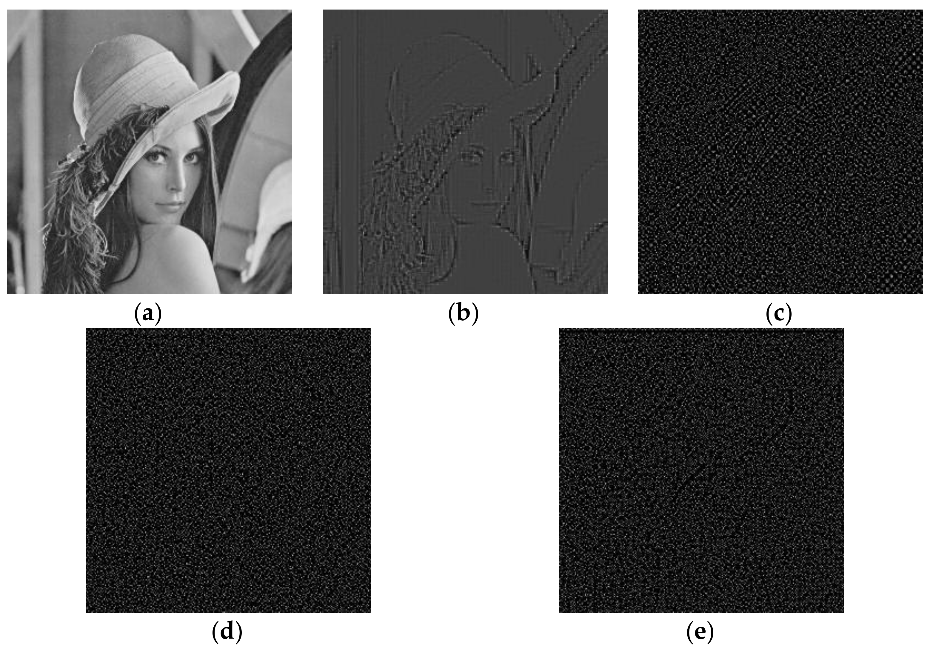
  • Step 1: The host image is firstly divided into 2 × 2 image blocks, and then the SVD transform is conducted on each block.
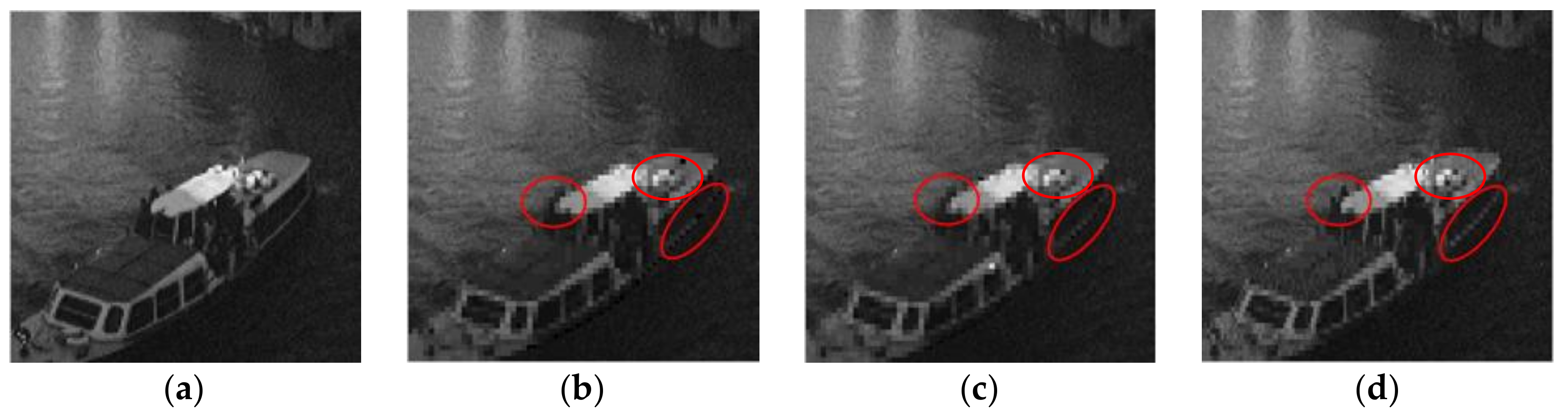
  • Step 2: For each block after SVD, the product of the left and right singular vectors (the first sub-image u 1 v 1 T ) is calculated. For smooth blocks, the values in u 1 v 1 T are approximately equal to 1/2 (0.5). Based on this point, two thresholds around 0.5, T 1 and T 2 are identified to label the pixels in u 1 v 1 T . For a pixel in u 1 v 1 T , if the pixel value falls in the range of T 1 to T 2 , the pixel will be judged as a smooth pixel, else it is judged as a texture pixel.
  • Step 3: Calculating the number of the smooth pixels in 2 × 2 block, if the number is larger than 3, the corresponding image block will be determined as a smooth block, else the block is determined as a texture block.
In this process, the interval between T 1 and T 2 plays an important role for the block classification result. If the interval between these two thresholds is too large, more image blocks would be determined as smooth blocks. On the contrary, if the interval is too small, more texture blocks will be obtained. However, if a texture block is falsely judged as a smooth block, the recovery data of this texture block would be insufficient and cannot adequately reflect the texture feature of this block. Consequently, the restored image will become severely blurred. Conversely, if there are too many texture blocks in the image, it will lead to the data redundancy for original smooth blocks in image recovery process. In this paper, the thresholds, T 1 = 0.48 and T 2 = 0.52 , are manually selected through a large number of testing experiments.

3. The Proposed Scheme

The proposed variable capacity fragile watermarking scheme is developed in this section, which includes three main processes: watermark generation and embedding processes, three-level tamper detection process, and image recovery process.

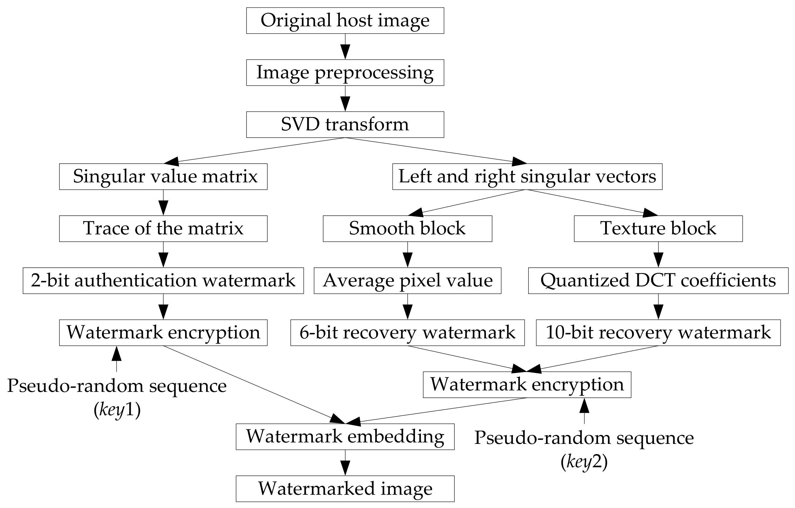
3.1. Watermark Generation and Embedding

The watermark generation and embedding processes are performed in the sending side. Figure 2 shows the block diagram of watermark generation and embedding processes. The proposed watermarking scheme is a block-based algorithm. In other words, the watermark generation and embedding processes are completed based on the image blocks. In addition, the watermarking bits are finally embedded into the LSBs of each block. Therefore, before watermark generation, the original image needs to be preprocessed. The original host image with size of M × M is firstly split into 2 × 2 image blocks. For each block, the three LSBs of each pixel are then removed. After preprocessing, the range of each pixel in the block goes from 0 to 31. For fragile watermarking with self-recovery ability, the watermark information of each block includes two parts: authentication watermark and recovery watermark. The generation processes of these two watermarks are described in the following subsections.

3.1.1. Authentication Watermark

From the analysis in Section 2, we know that the singular values contain the most energy information of a matrix. Therefore, in this paper, the singular values are adopted as the authentication watermark. For each block after preprocessing, the SVD transform is performed. The trace of singular value matrix is calculated and coded into binary from B = ( b 1 , b 2 , , b 8 , b 9 ) . Then two exclusive-or-operations are applied to B, and 2-bit authentication watermark P = ( p 1 , p 2 ) is generated for each block, which can be expressed as:
p 1 = b 1 b 2 b 8 b 9 ,   p 2 = b 2 b 4 b 6 b 8 .
To enhance the security of authentication watermark, a binary pseudo-random sequence S 1 = ( s 1 , s 2 ) with a secret key k e y 1 is produced, where s 1 and s 2 are the elements in S 1 . Then the encrypted authentication watermark P e = ( p e 1 , p e 2 ) is generated by:
p e 1 = p 1 s 1 ,   p e 2 = p 2 s 2 .

3.1.2. Recovery Watermark

To generate the variable capacity recovery watermark, the image blocks are firstly classified into smooth blocks and texture blocks using the classification method mentioned in Section 2. A mark symbol h is used to label the blocks. If the block belongs to the smooth block, then h = 0 , else h = 1 . For different blocks, alterable length recovery watermark is produced.
For smooth block, the average value of its four pixels is served as the recovery watermark, which has a range from 0 to 31. This average value is turned into binary form, and then we get 5 bits recovery watermark for smooth block ( r 1 , r 2 , r 3 , r 4 , r 5 ) .
Compared to smooth block, the texture block contains more image content. Once the texture block is tampered, more watermark information is needed to reconstruct the texture block. The DCT transform has good energy concentration characteristic. Most information of an image is concentrated upon just few low frequency DCT coefficients, while other coefficients are close to 0. In [33], Singh, D. and Singh, S.K. proposed a DCT-based self-recovery fragile watermarking method. In their scheme, the host image is firstly divided into 2 × 2 blocks, and the DCT transform is applied to each block. After analysis of the DCT coefficients in each block, the authors found that, for image block with size of 2 × 2, the DC coefficient and the first AC coefficient accounts for a large component for a block, while the other two coefficients are either 0 or negligible values. Based on this property, they introduced a quantization method for DC and the first AC coefficient and produced 10 bits recovery watermark for each block. Though this method achieves good performance in image recovery, the watermark capacity for each block is constant. Inspired by [33], the generation process of the recovery watermark for texture blocks is developed below:
  • Step 1: To generate appropriate length recovery watermark, the image block C = ( c i j ) 2 × 2 after preprocessing is further adjusted by Equation (5), and then we get the processed image block C = ( c i j ) 2 × 2 .
    c i j = c i j 2 8 ,   i , j = 1 , 2 ,
    where . is the rounding-down operation.
  • Step 2: For each block C , the DCT transform is applied, and then we get the DCT coefficient matrix D = ( d i j ) 2 × 2 :
    D = [ d 11 d 12 d 21 d 22 ] ,
  • Step 3: To generate the recovery watermark, the DC coefficient d 11 is rounded and coded into 5 bits watermark including 1 bit sign flag and 4 bits coefficient encoding result, and the AC coefficient d 12 is coded into 4 bits watermark including 1 bit sign flag and 3 bits coefficient encoding result. It should be noted that if the coefficients are out of the coding range, they need to be modestly adjusted. For example, if the absolute value of d 11 is larger than 15, then it should be adjusted and make it equal to 15.
After the above watermark generation processes, we get different recovery watermarks for different blocks finally: 6 bits for smooth blocks and 10 bits for texture blocks, which can be expressed as:
R = ( h , r 1 , r 2 , , r i ) ,   i = { 5 , h = 0 , 9 , h = 1 .
To ensure the security of recovery watermark, a same encryption method mentioned in Section 3.1.1 is adopted to encrypt the recovery watermark, which can be expressed as:
R e = R S 2 ,
where S 2 is another binary pseudo-random sequence generated by secret key k e y 2 , and R e is the encrypted watermark.

3.1.3. Watermark Embedding

Before watermark embedding, a block mapping sequence is generated by:
X = ( k × X ) mod N + 1 ,
where X is the index of image block, X is the index of the corresponding mapping block, N is the total number of blocks, and k [ 1 , N 1 ] is a prime number. To improve the image recovery ability and reduce the synchronous tampering problem, a push-aside operation proposed in [34] is applied to further disrupt the order of the block mapping sequence.
To complete the watermark embedding process, the encrypted authentication watermark of an image block is embedded into the 2 LSBs of the first pixel in block itself. The encrypted recovery watermark is embedded into the 2 or 3 LSBs of its mapping block. That means the watermark capacity is 2–3 bpp (bit per pixel). Besides, the secret keys ( k , k e y 1 , and k e y 2 ) used in watermark embedding process will be sent to the receiver through a secure communication channel. Generally speaking, it is more convenient and secure to transmit three secret values than to transmit the images. Table 1 lists the parameters used in watermark generation and embedding processes.

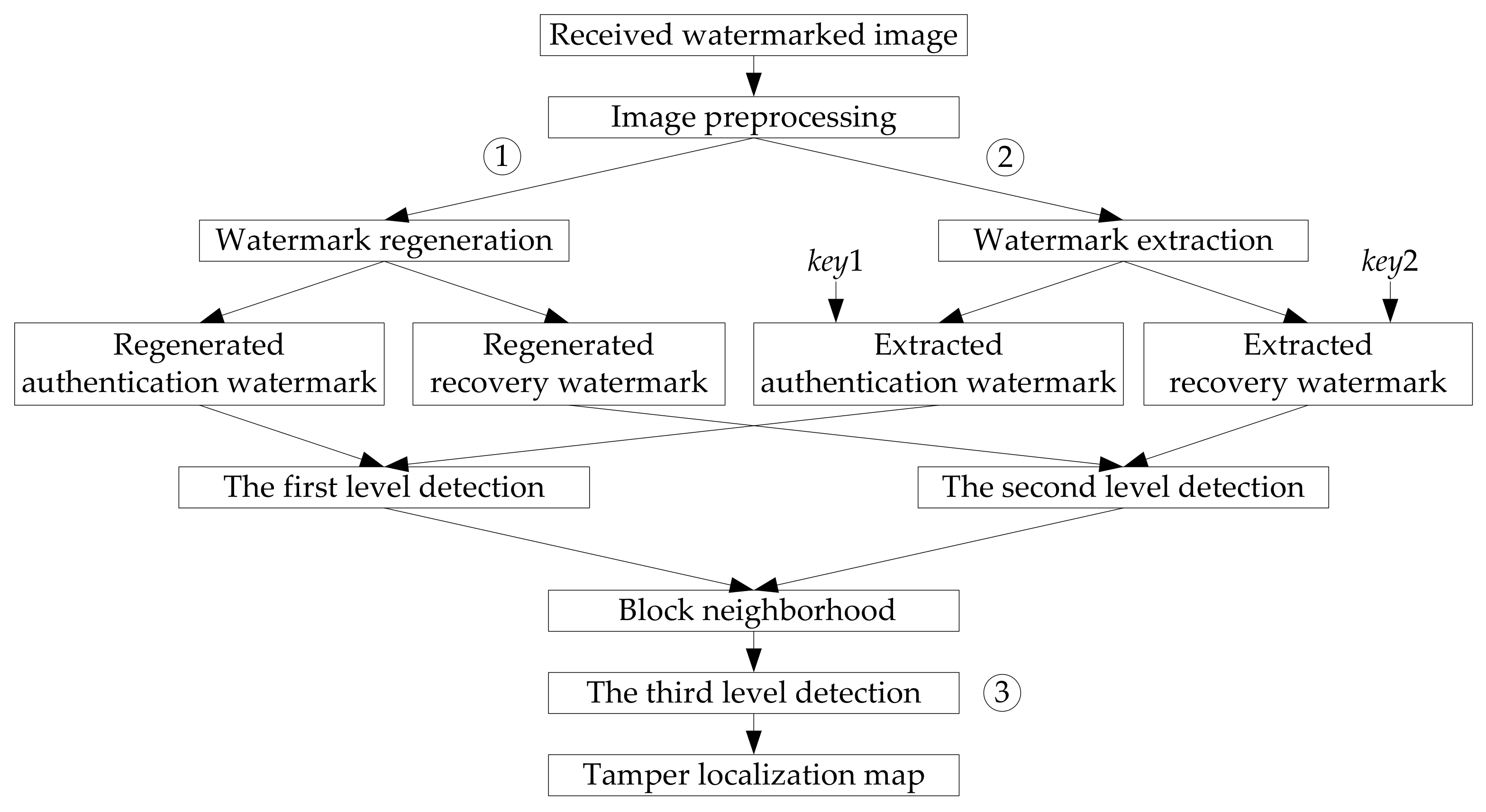
3.2. Three-Level Tamper Detection

In the receiving or detection side, the received image might be tampered by potential attackers. To detect and locate the tampered regions, a three-level tamper detection strategy [25] is applied in the proposed method, which is shown in Figure 3.
(1)
In the first level detection (① in Figure 3), the encrypted authentication watermark is firstly extracted from the image block, which can be expressed as P e = ( p e 1 , p e 2 ) . With the secret key k e y 1 , a corresponding decryption process is conducted to the extracted watermark, and then we get the decrypted authentication watermark P = ( p 1 , p 2 ) . According to the generation process of authentication watermark in Section 3.1.1, a new authentication watermark for this block is regenerated, which is expressed as P = ( p 1 , p 2 ) . If P P , then the detected block is marked as a tampered block, else it is marked as an authentic block.
(2)
In the second level detection (② in Figure 3), the recovery watermark of the block is firstly extracted from its mapping block generated by Equation (9), which is expressed as R e . Then, with the secret key k e y 2 , a decryption process is performed on R e , and the decrypted recovery watermark R is obtained. If the block is a smooth block, the length of R is 6 bits, else the length of R is equal to 10 bits. Accordingly, a new recovery watermark R for the current block is regenerated, which has the same process as Section 3.1.2. At last, a comparison process is applied for the extracted recovery watermark R and the newly created watermark R . If R R , then the detected block is marked as a tampered block, else it is marked as an authentic block.
(3)
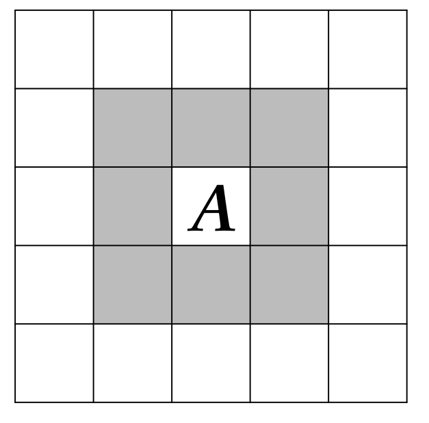
After the first two level detections, we get the preliminary tamper detection result. However, due to the fact that the tamper detection process is based on the image blocks, there might be a probability of misjudgment. In other words, an authentic image block might be falsely detected as a tampered block, and a truly tampered block might be detected as an authentic block. To further improve the tamper detection accuracy, the third level detection is applied (③ in Figure 3). This process is completed by using the block-neighborhood tampering characterization [27]. For a suspicious block A shown in Figure 4, n is used to represent the number of the blocks that are detected as tampered in its block-neighborhood (the blocks in gray in Figure 4). If the central image block A is a valid block while the number of the tampered blocks in its block-neighborhood is more than 7 ( n 7 ), then the block A will also be determined as an invalid block. If the central image block A is a tampered block while the number n is less than 2 ( n < 2 ), then the image block A will be determined as a valid block.
After the three-level detection, we get the tamper localization map, where the pixel values in tampered regions are set as 0.

3.3. Image Recovery

Corresponding to the generation process of recovery watermark in Section 3.1.2, the image recovery process is also divided into two kinds of situations: recovery for smooth blocks and recovery for texture blocks.
(1)
For tampered smooth block, the recovery watermark is the average pixel value of original block. To reconstruct the block, the recovery watermark is first extracted from its mapping block. After decryption and the binary-to-decimal conversion, we get the final recovery data.
(2)
For invalid texture block, the recovery watermark is the quantized DCT coefficients. According to the inverse process of the watermark generation process (Steps 1–3) given in Section 3.1.2, the recovery data for texture block can be obtained.
All the recovery data are in the range from 0 to 31. To restore the block, the 5 MSBs of each pixel are padded with the recovery data, while its 3 LSBs are set as 0.
For the blocks that are unsuccessfully restored, the average values of the valid pixels in its block neighborhood are used to replace the four pixels in the block. After the image recovery process, the tampered image can be restored with a good quality.

4. Experimental Results and Comparison Analysis

In this section, we evaluate and analyze the performance of the proposed method in three aspects: watermark imperceptibility, tamper detection accuracy, and self-recovery ability. Ten standard test images with size of 256 × 256 are adopted as the carrier images, which are presented in Figure 5. All the experiments are performed on a computer with 3.10 GHz Intel Core i3 processor and 6 GB memory. The simulation environment is MATLAB R2012a (the MathWorks, Natick, MA, USA).

4.1. Imperceptibility Analysis

It is known that the quality of watermarked image determines the performance of watermark imperceptibility. The better the quality of watermarked image is, the better the watermark invisibility will be. Accordingly, the watermark information hidden in the watermarked image is more difficult to be perceived by human eyes. In this paper, the peak signal-to-noise ratio (PSNR) is applied to assess the watermarked image’s quality, which is defined as:
PSNR = 10 log 10 255 2 MSE ( dB ) ,
MSE = 1 M × M i = 1 M j = 1 M [ I ( i , j ) I w ( i , j ) ] 2 ,
where MSE is the mean square error between test image I and its watermarked version I w , and M × M denotes the image size.
From the watermark embedding process, we can see that different blocks contain different length of watermark information. The watermark capacity is 2–3 bpp, and the absolute difference between the pixel values before and after watermark embedding is 0–7. Supposing that the probability of the change for each LSB is the same, we calculate the expectation value of PSNR from two cases:
(1)
For the blocks whose 2 LSBs are embedded by 8 bits watermark information, the expectation value of MSE is 1.5 2 , then the PSNR’s expectation can be computed by:
PSNR = 10 log 10 ( 255 2 1.5 2 ) = 44.61   ( dB ) ,
(2)
For the blocks whose 3 LSBs are embedded by 12 bits watermark information, the expectation value of MSE is 3.5 2 , then the PSNR’s expectation is calculated by:
PSNR = 10 log 10 ( 255 2 3.5 2 ) = 37.25   ( dB ) ,
In practical application, if the PSNR value of a processed image is larger than 35 dB, people cannot tell the difference between the original image and its processed version.
Table 2 gives the analysis of watermark imperceptibility for the test images shown in Figure 5. From the table, it can be observed that the more the texture blocks in host image are, the greater the watermark capacity will be. Accordingly, the PSNR values of the watermarked images will be decreased. However, from the final column of the table, we can see that the PSNR values of the ten watermarked images are all larger than 38 dB, which proves that the proposed variable capacity fragile watermarking achieves good watermark imperceptibility.

4.2. Performance of Tamper Detection and Self-Recovery

To evaluate the tamper detection precision of the presented method, the false negative ratio (FNR) and false positive ratio (FPR) [35] are employed in this paper. The definitions of FPR and FNR can be expressed as:
FNR = N tu N t ,   FPR = N ut N u ,
where N t refers to the number of truly tampered blocks, N u is the number of untampered blocks, N tu is the number of tampered blocks that are regarded as untampered, and N ut denotes the number of untampered blocks that are regarded as tampered. As the formula implies, the FNR is used to measure the proportion of the invalid blocks that are mistakenly determined as authentic blocks, while the FPR is used to measure the proportion of the authentic blocks that are falsely judged as invalid blocks. The lower FNR and FPR indicate a better tamper detection accuracy. The recovery ability is evaluated by the PSNR between the original watermarked image and the restored image.
To test the performance of the presented method in tamper detection and self-recovery, various attacks are performed on the watermarked images. Besides, we compare the presented method with other two self-recovery fragile watermarking methods in [13,25]. Reference [13] is a watermarking scheme with a fixed watermark capacity, and reference [25] is variable capacity watermarking scheme.

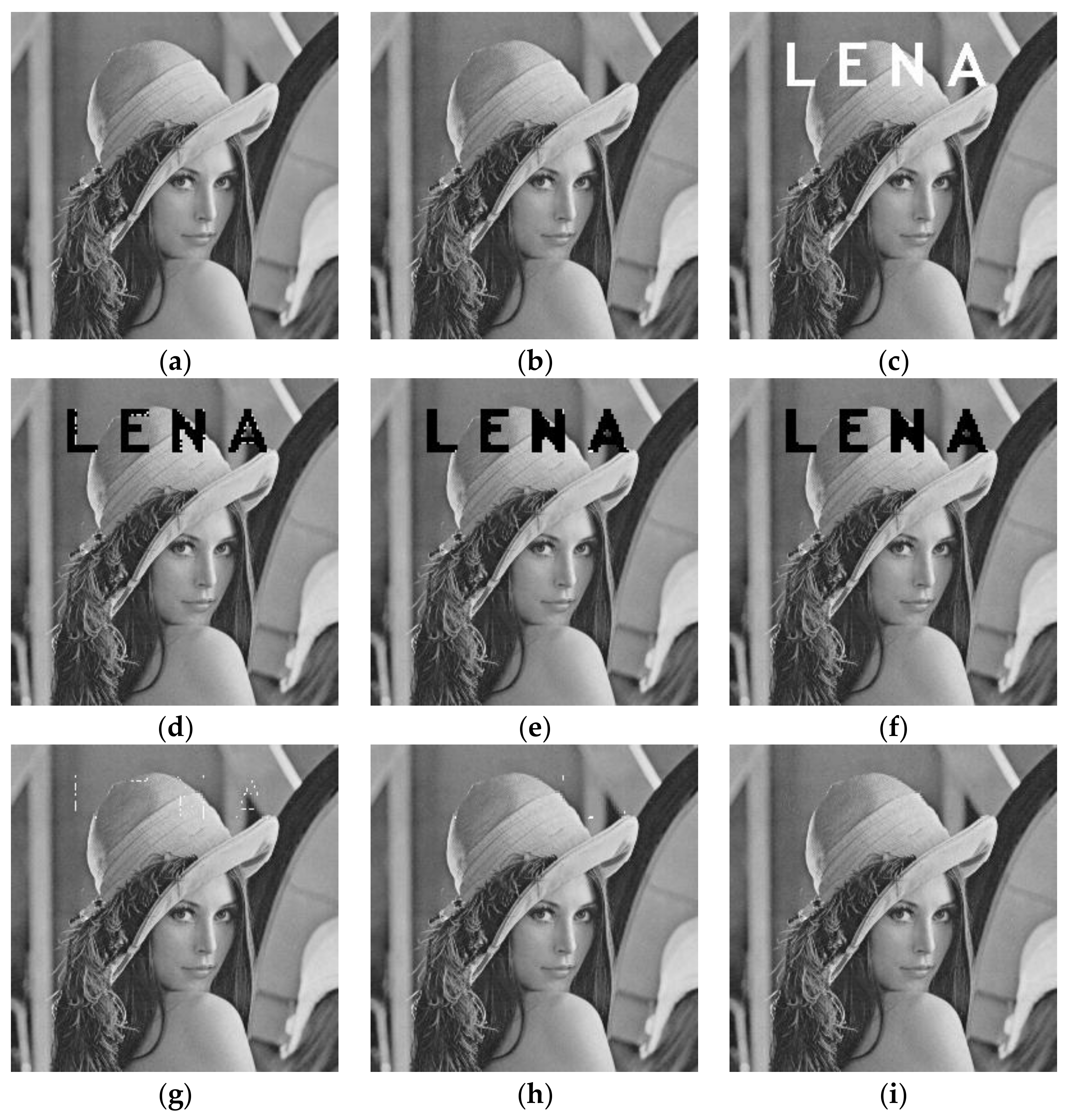
4.2.1. Text Addition Attack

Figure 6 shows the performance of tamper detection and recovery for text addition attacks. A text logo “LENA” is added to the watermarked Lena image, which is shown in Figure 6c. The tamper localization maps of these three methods are presented in Figure 6d–f. From the detection results, it can be seen that the detection results in [13,25] have obvious missed detection problem around the tampered regions, especially in [13]. This is because it only has one-level detection in [13], which cannot provide a reliable detection result. Figure 6g–i gives the corresponding reconstructed images. From the figures, we can learn that there leaves some tampering traces on the images restored by [13,25], which are caused by the poor tamper localization result. These traces cannot be restored during image recovery process. Compared to references [13,25], the recovered Lena image in the proposed method has good subjective effect. It is almost the same as the original watermarked image. To make a better comparison, Table 3 lists the FPR, FNR, and the PSNR of recovered images. Due to the use of the three-level detection strategy, the FPR of the proposed method is slightly higher that [13,25]. However, the proposed method has the lowest FNR among these three methods. This good tamper detection result also contributes a better image quality for the restored image. The PSNR value of the restored image in the proposed method is more than 45 dB.

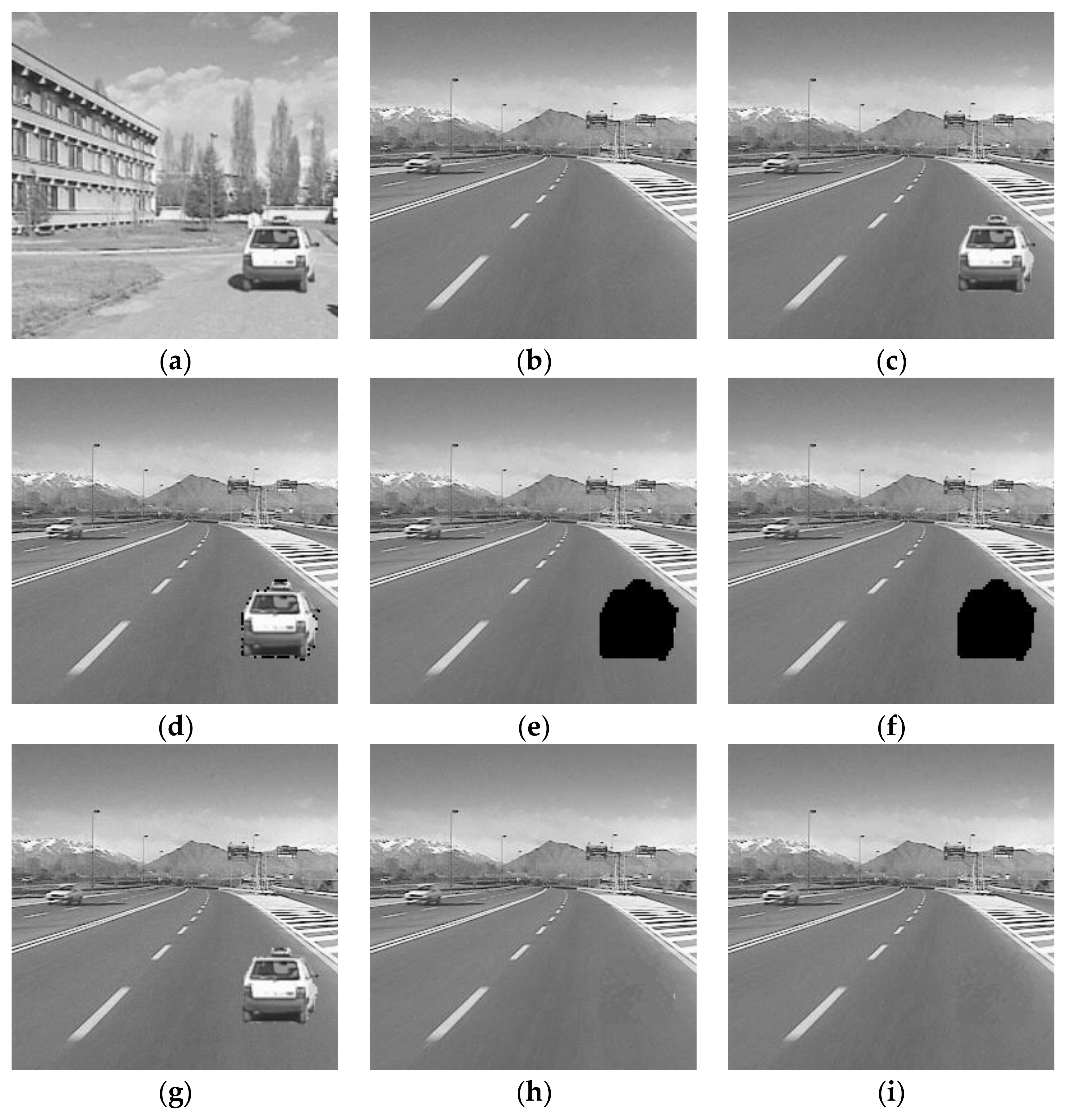
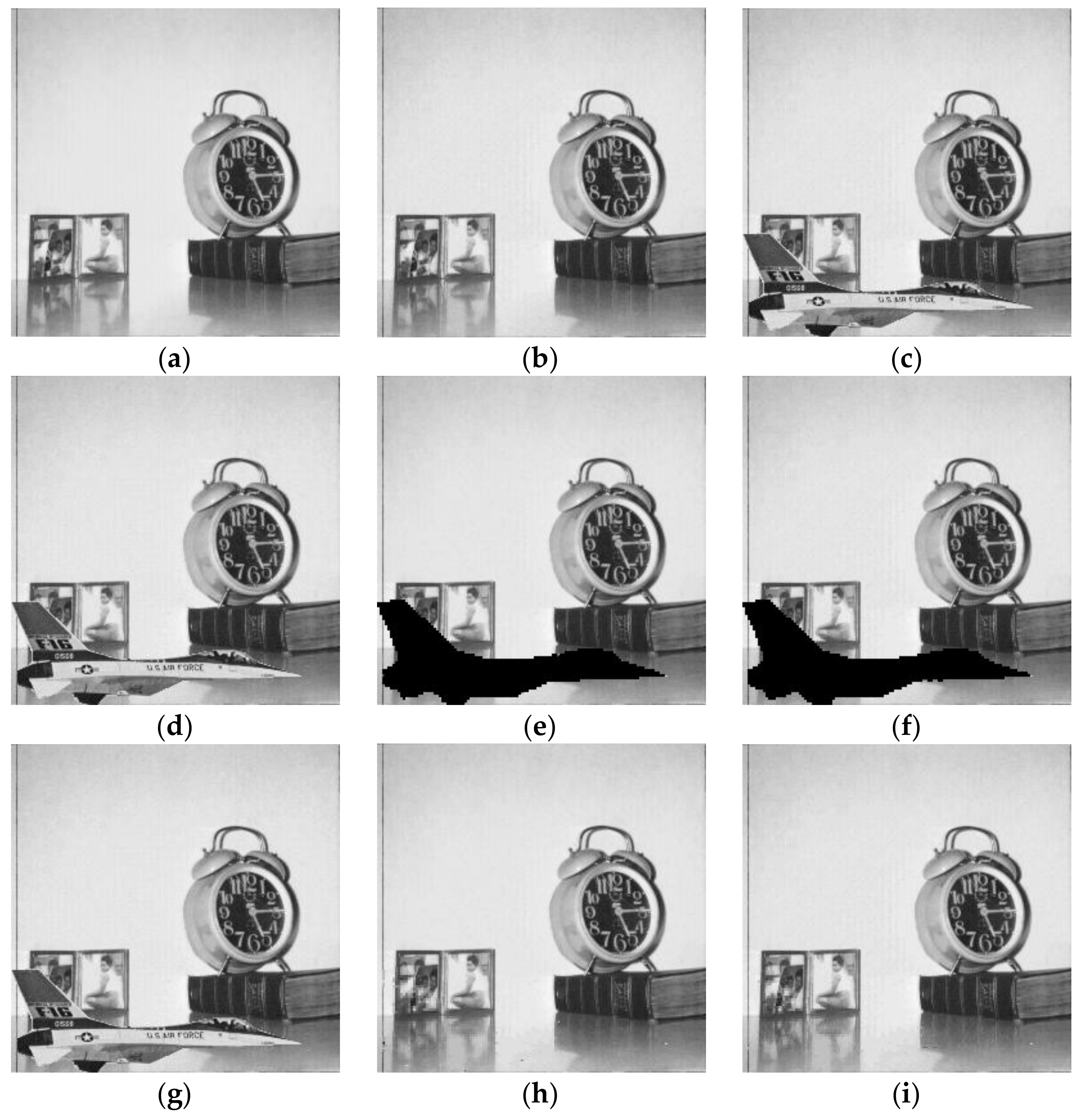
4.2.2. Copy-Move Attack

In Figure 7, a sky region from another image is copied and pasted into watermarked Goldhill image. If the attackers choose tampered region premeditatedly, it will be difficult for the receiver to find the trace of tampering. From the detection results shown in Figure 7d–f, it can be observed that the detection results of references [13,25] have serious missed detection problem, while the proposed method can locate the tampered region precisely. These image blocks that are falsely detected in the former two algorithms make the restored images having a serious trace of tampering, which are shown in Figure 7g,h, respectively. Table 4 gives the performance comparisons of these three methods in FPR, FNR, and PSNR of recovered images. The FNR of the proposed method is much lower than the other two methods, which is only about 0.4%. From the restored image shown in Figure 7i and its PSNR value given in Table 4, it can be proved that the recovered image has a good image quality subjectively and objectively.

4.2.3. Collage Attack

Collage attack introduced in [36] is a special attack for the watermarking method based on block-independent. Figure 8 gives the tamper detection and recovery performance for collage attack. A car from watermarked Car1 image (Figure 8a) is copied and inserted into watermarked Car2 image (Figure 8b) without changing its relative location. The detection results in Figure 8d–f indicate that the proposed method and [25] can resist the collage attack and locate the splicing area successfully. Only the border of the tampered area is detected in Figure 8d. The reason is that the method proposed in [13] does not break the block-independent characteristic during watermark generation and embedding processes. From the restored images shown in Figure 8g–i, it can be observed that both the proposed method and [25] can restore the tampered image with good subjective quality. The watermarking method in [13] cannot reconstruct the tampered regions due to the fact that the collage attack has been survived from the detection process. From Table 5, we can see the recovered images obtained by the proposed method and [25] have similar PSNR values. However, compared to [25], the FNR of the proposed method is much lower, which suggests a better tamper localization result.

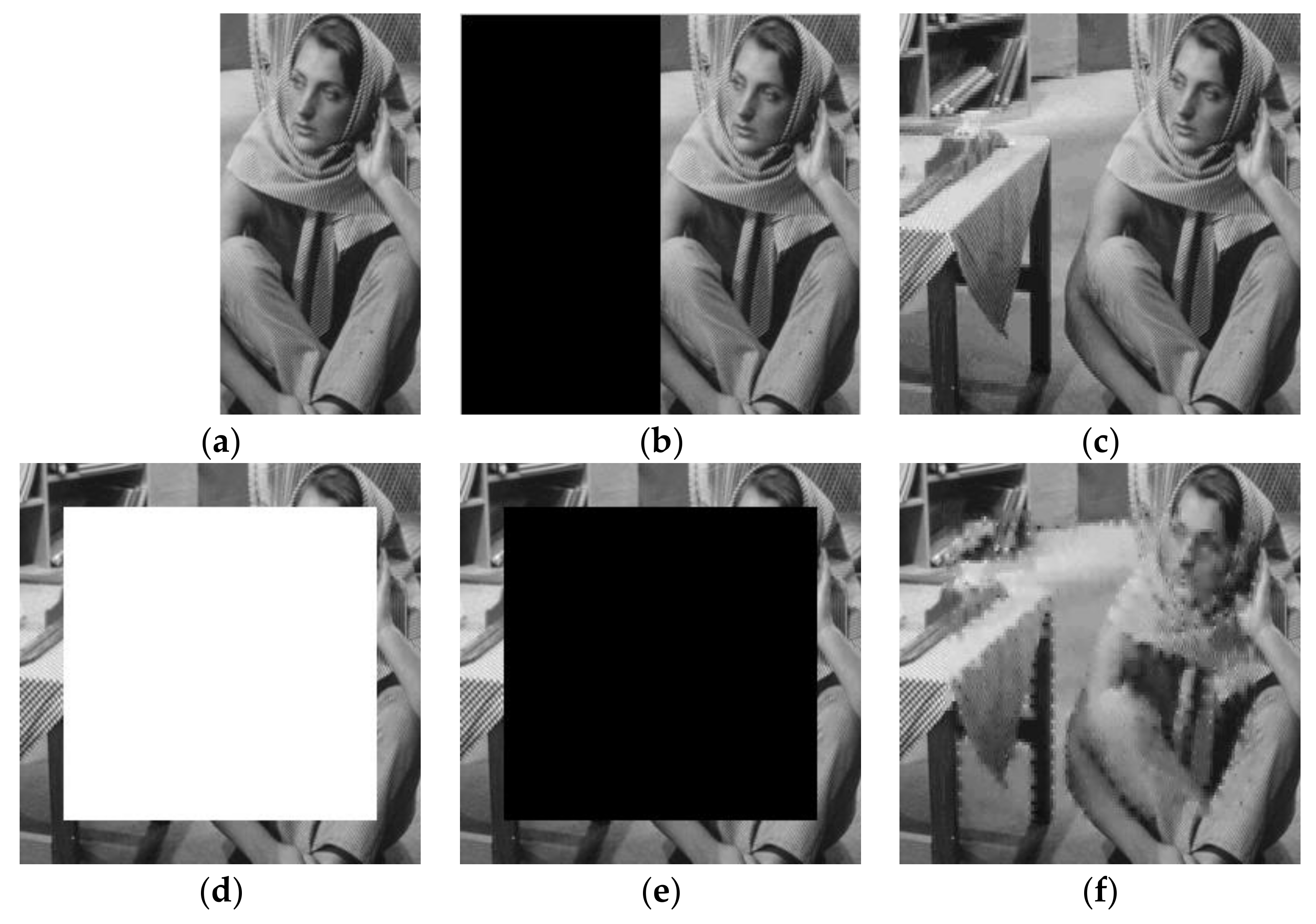
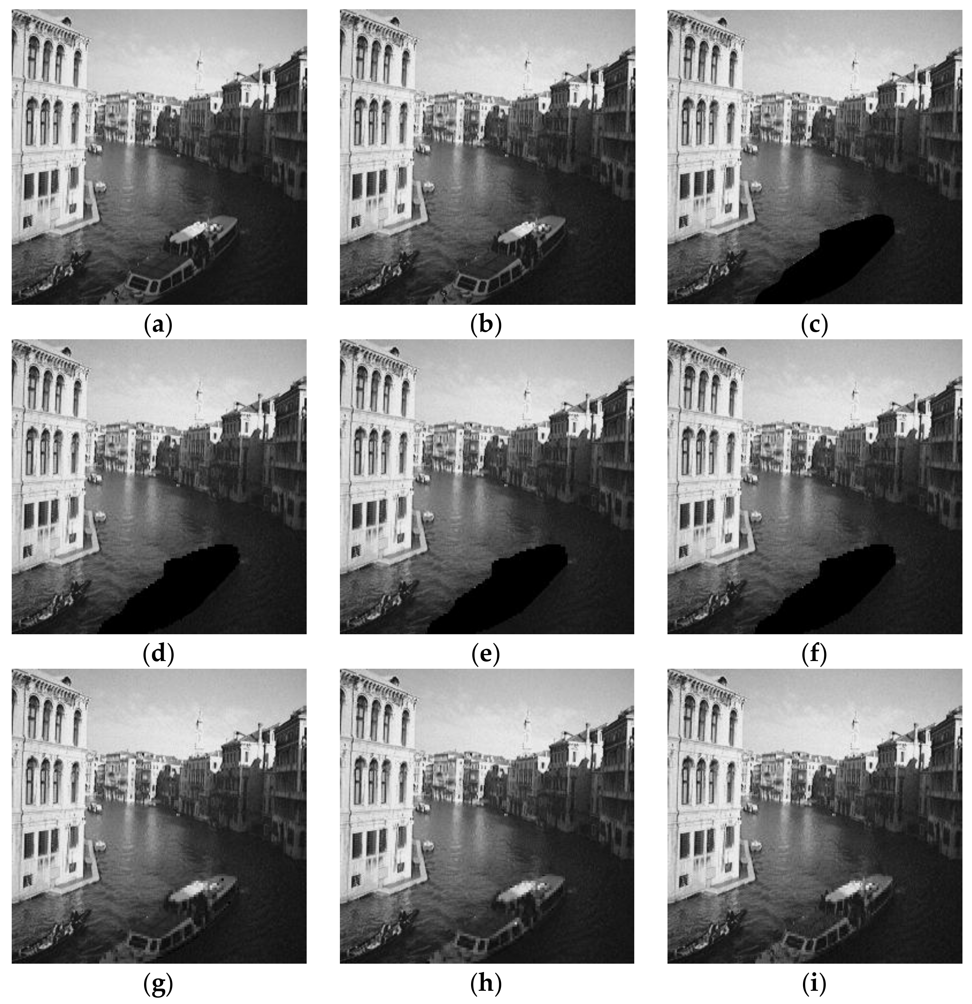
4.2.4. Image Deletion Attack

To test the performance of the proposed method under deletion attack, Figure 9 exhibits the comparison results of these three methods in tamper detection and recovery. The ship in watermarked Venice image is directly deleted from the image. From the detection results given in Figure 9d–f, we can see that all these three methods can find the tampered regions precisely, and the restored images presented in Figure 9g–i have almost the same subjective image quality. However, due to the different recovery strategies, there is still a difference for the restoration of image details. In order to show the restoration effect more intuitively, Figure 10 gives the partial enlarged details of the restored images in Figure 9g–i. It can be observed that all the restored images have become blurred because of the block-wise recovery method. However, compared to the restored images in [13,25], the restored image by the proposed scheme is relatively smooth, and it is much closer to the original ship image in Figure 10a, especially in the places that have been circled in red. From the objective data listed in Table 6, we can draw the same conclusion that these three methods achieve similar tamper detection performance. Though the FPR of the proposed scheme are slightly higher than the other methods, the PSNR value of the restored image by the proposed scheme has been improved by 2 dB. This conclusion further proves that the recovery strategy designed in the proposed scheme has an advantage over references [13,25].

4.2.5. Content-Only Attack

Content-only attack [37] is another special attack that is commonly used in fragile watermarking. In some watermarking schemes with recovery ability, the authentication bits of a block are completely irrelevant to the image content. The content-only attack exploits this flaw and alters the image content while keeping their watermarking bits untouched. In this way, the image content has been tampered, but the watermarking bits used for tamper detection remain unchanged, which would lead to the authentication failure in the detection side. The proposed scheme has avoided this drawback. The feature of the singular values in each block is adopted as the authentication watermark. Besides, the use of three-level detection strategy can also protect the watermarked image from the content-only attack effectively.
Figure 11 shows the algorithm performance comparisons for content-only attack. The airplane is inserted into the watermarked Clock image without changing its watermarking bits. From the detection results presented in Figure 11d–f, we can observe that reference [13] has failed in detecting this attack. This is because its generation processes of authentication watermark and recovery watermark are mutually independent, which gives a chance for content-only attack. The proposed scheme and the method in [25] avoid this shortcoming and achieve similar detection results subjectively. Due to the authentication failure, the attacked image in [13] cannot be recovered. To make a better comparison for the restored images, Figure 12 exhibits the partial enlarged details of the restored images shown in Figure 11h,i. As shown in the enlarged drawing, there are some image blocks (as circled in red) that are unnaturally distributed in the restored image of reference [25]. Besides, compared to reference [25], the restored image by the proposed scheme is much closer to the original image.
Table 7 lists the corresponding experimental data. From the table, we can learn that the FNR of the proposed method is little bit lower than Chen et al.’s method [25]. The PSNR value of the recovered image obtained by the proposed scheme is improved more than 3 dB, which is benefited from the effective block classification method and recovery strategy.

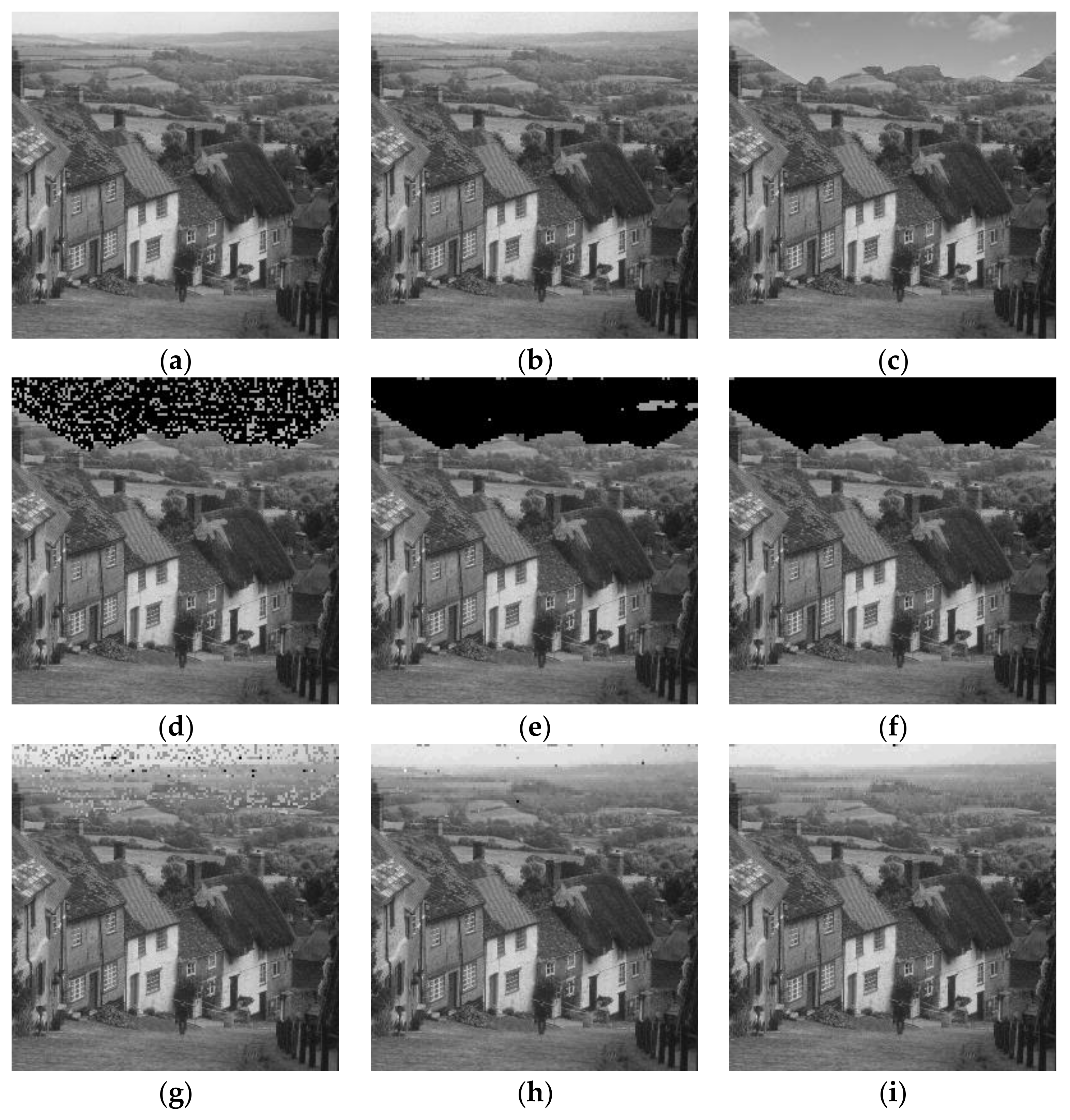
4.2.6. Large Area Tampering

To test the performance of the proposed method for large area tampering, Figure 13 gives the tamper detection and image recovery results under large area tampering, where the tampering ratios are 50% in the left part and 80% in the middle, respectively. From the figures, it can be seen that when half of the image has been modified, the recovered image still has a good image quality subjectively and objectively; when the tampering ratio is up to 80%, the restored image becomes seriously blurred and its PSNR value is decreased to 19 dB. However, the basic content of the image is still recognizable, which proves that the proposed method is effective for large area tampering.

5. Conclusions

Based on the characteristics of SVD and DCT, a self-recovery fragile watermarking with variable watermark capacity is presented in this paper. The trace of singular value matrix of each block is served as the authentication watermark, and its left and right singular vectors are used to classify the image blocks into smooth blocks and texture blocks. For different blocks, different length recovery watermark is generated. In other words, the watermark capacity is variable. To ensure the security of the algorithm, the watermark is encrypted by binary pseudo-random sequences before embedding. Several experiments are conducted to test the performance of the presented method. The experimental results prove that the presented fragile watermarking scheme has good watermark imperceptibility. Besides, the use of three-level detection strategy improves the tamper detection accuracy greatly. Compared with other two self-recovery watermarking methods, the reconstructed images obtained by the presented method have a better image quality. For the future task, we will analyze the selections of different parameters and its specific effects on the performance of the proposed method. Based on the analysis, we will further improve the tamper detection accuracy and recovery ability of the proposed method.

Acknowledgments

This work was supported by the National Natural Science Foundation of China (No. 61702303, No. 61201371); the Natural Science Foundation of Shandong Province, China (No. ZR2017MF020, No. ZR2015PF004); and the Research Award Fund for Outstanding Young and Middle-Aged Scientists of Shandong Province, China (No. BS2013DX022).

Author Contributions

Chengyou Wang and Heng Zhang conceived the algorithm and designed the experiments; Heng Zhang performed the experiments; Chengyou Wang and Xiao Zhou analyzed the results; Heng Zhang drafted the manuscript; Chengyou Wang, Heng Zhang, and Xiao Zhou revised the manuscript. All authors read and approved the final manuscript.

Conflicts of Interest

The authors declare no conflict of interest.

References

  1. Asikuzzaman, M.; Pickering, M.R. An overview of digital video watermarking. IEEE Trans. Circuits Syst. Video Technol. 2017, 1–23. [Google Scholar] [CrossRef]
  2. Asikuzzaman, M.; Alam, M.J.; Lambert, A.J.; Pickering, M.R. Imperceptible and robust blind video watermarking using chrominance embedding: A set of approaches in the DT CWT domain. IEEE Trans. Inf. Forensics Secur. 2014, 9, 1502–1517. [Google Scholar] [CrossRef]
  3. Asikuzzaman, M.; Alam, M.J.; Lambert, A.J.; Pickering, M.R. Robust DT CWT-based DIBR 3D video watermarking using chrominance embedding. IEEE Trans. Multimed. 2016, 18, 1733–1748. [Google Scholar] [CrossRef]
  4. Huynh-The, T.; Banos, O.; Lee, S.; Yoon, Y.; Le-Tien, T. Improving digital image watermarking by means of optimal channel selection. Expert Syst. Appl. 2016, 62, 177–189. [Google Scholar] [CrossRef]
  5. Huynh-The, T.; Hua, C.H.; Tu, N.A.; Hur, T.; Bang, J.; Kim, D.; Bilal Amin, M.; Kang, B.H.; Seung, H.; Lee, S. Selective bit embedding scheme for robust blind color image watermarking. Inf. Sci. 2018, 426, 1–18. [Google Scholar] [CrossRef]
  6. Asikuzzaman, M.; Alam, M.J.; Lambert, A.J.; Pickering, M.R. A blind watermarking scheme for depth-image-based rendered 3D video using the dual-tree complex wavelet transform. In Proceedings of the IEEE International Conference on Image Processing, Paris, France, 27–30 October 2014; pp. 5497–5501. [Google Scholar]
  7. Asikuzzaman, M.; Alam, M.J.; Pickering, M.R. A blind and robust video watermarking scheme in the DT CWT and SVD domain. In Proceedings of the Picture Coding Symposium, Cairns, Australia, 31 May–3 June 2015; pp. 277–281. [Google Scholar]
  8. Han, S.H.; Chu, C.H. Content-based image authentication: Current status, issues, and challenges. Int. J. Inf. Secur. 2010, 9, 19–32. [Google Scholar] [CrossRef]
  9. Sreenivas, K.; Prasad, V.K. Fragile watermarking schemes for image authentication: A survey. Int. J. Mach. Learn. Cybern. 2017, 1–26. [Google Scholar] [CrossRef]
  10. Azeroual, A.; Afdel, K. Real-time image tamper localization based on fragile watermarking and Faber-Schauder wavelet. AEU Int. J. Electron. Commun. 2017, 79, 207–218. [Google Scholar] [CrossRef]
  11. Rakhmawati, L.; Rochmawati, N. Review of some existing work for self-recovery fragile watermarking algorithms. In Proceedings of the 2nd Annual Applied Science and Engineering Conference, Bandung, Indonesia, 24 August 2017; Volume 288. [Google Scholar]
  12. Dadkhah, S.; Manaf, A.A.; Hori, Y.; Hassanien, A.E.; Sadeghi, S. An effective SVD-based image tampering detection and self-recovery using active watermarking. Signal Process. Image Commun. 2014, 29, 1197–1210. [Google Scholar] [CrossRef]
  13. Tong, X.J.; Liu, Y.; Zhang, M.; Chen, Y. A novel chaos-based fragile watermarking for image tampering detection and self-recovery. Signal Process. Image Commun. 2013, 28, 301–308. [Google Scholar] [CrossRef]
  14. Qin, C.; Ji, P.; Wang, J.W.; Chang, C.C. Fragile image watermarking scheme based on VQ index sharing and self-embedding. Multimed. Tools Appl. 2017, 76, 2267–2287. [Google Scholar] [CrossRef]
  15. Zhang, X.P.; Xiao, Y.Y.; Zhao, Z.M. Self-embedding fragile watermarking based on DCT and fast fractal coding. Multimed. Tools Appl. 2015, 74, 5767–5786. [Google Scholar] [CrossRef]
  16. Singh, D.; Singh, S.K. Effective self-embedding watermarking scheme for image tampered detection and localization with recovery capability. J. Vis. Commun. Image Represent. 2016, 38, 775–789. [Google Scholar] [CrossRef]
  17. Qian, Z.X.; Feng, G.R.; Zhang, X.P.; Wang, S.Z. Image self-embedding with high-quality restoration capability. Dig. Signal Process. 2011, 21, 278–286. [Google Scholar] [CrossRef]
  18. Zhang, X.P.; Wang, S.Z. Fragile watermarking with error-free restoration capability. IEEE Trans. Multimed. 2008, 10, 1490–1499. [Google Scholar] [CrossRef]
  19. Cao, F.; An, B.W.; Wang, J.W.; Ye, D.P.; Wang, H.L. Hierarchical recovery for tampered images based on watermark self-embedding. Displays 2017, 46, 52–60. [Google Scholar] [CrossRef]
  20. Huo, Y.R.; He, H.J.; Chen, F. Alterable-capacity fragile watermarking scheme with restoration capability. Opt. Commun. 2012, 285, 1759–1766. [Google Scholar] [CrossRef]
  21. Zhang, X.P.; Wang, S.Z.; Qian, Z.X.; Feng, G.R. Reference sharing mechanism for watermark self-embedding. IEEE Trans. Image Process. 2011, 20, 485–495. [Google Scholar] [CrossRef] [PubMed]
  22. Qin, C.; Wang, H.L.; Zhang, X.P.; Sun, X.M. Self-embedding fragile watermarking based on reference-data interleaving and adaptive selection of embedding mode. Inf. Sci. 2016, 373, 233–250. [Google Scholar] [CrossRef]
  23. Bravo, S.S.; Calderon, F.; Li, C.T.; Nandi, A.K. Fast fragile watermark embedding and iterative mechanism with high self-restoration performance. Dig. Signal Process. 2018, 73, 83–92. [Google Scholar] [CrossRef]
  24. Chen, F.; He, H.J.; Wang, H.X. Variable-payload self-recovery watermarking scheme for digital image authentication. Chin. J. Comput. 2012, 35, 154–162. [Google Scholar] [CrossRef]
  25. Chen, F.; He, H.J.; Tai, H.M.; Wang, H.X. Chaos-based self-embedding fragile watermarking with flexible watermark payload. Multimed. Tools Appl. 2014, 72, 41–56. [Google Scholar] [CrossRef]
  26. Lian, S.G.; Sun, J.S.; Wang, J.W.; Wang, Z.Q. A chaotic stream cipher and the usage in video protection. Chaos Solitons Fractals 2007, 34, 851–859. [Google Scholar] [CrossRef]
  27. He, H.J.; Zhang, J.S.; Tai, H.M. Self-recovery fragile watermarking using block-neighborhood tampering characterization. In Proceedings of the 11th International Workshop on Information Hiding, Darmstadt, Germany, 8–10 June 2009; Lecture Notes in Computer Science. Springer: Berlin, Germany, 2009; Volume 5806, pp. 132–145. [Google Scholar]
  28. Nazari, M.; Sharif, A.; Mollaeefar, M. An improved method for digital image fragile watermarking based on chaotic maps. Multimed. Tools Appl. 2017, 76, 16107–16123. [Google Scholar] [CrossRef]
  29. Shi, H.; Wang, X.H.; Li, M.C.; Bai, J.; Feng, B. Secure variable-capacity self-recovery watermarking scheme. Multimed. Tools Appl. 2017, 76, 6941–6972. [Google Scholar] [CrossRef]
  30. Ansari, I.A.; Pant, M. Multipurpose image watermarking in the domain of DWT based on SVD and ABC. Pattern Recognit. Lett. 2017, 94, 228–236. [Google Scholar] [CrossRef]
  31. Roy, S.; Pal, A.K. An SVD based location specific robust color image watermarking scheme using RDWT and Arnold scrambling. Wirel. Pers. Commun. 2018, 98, 2223–2250. [Google Scholar] [CrossRef]
  32. Zhang, H.; Wang, C.Y.; Zhou, X. Fragile watermarking for image authentication using the characteristic of SVD. Algorithms 2017, 10, 27. [Google Scholar] [CrossRef]
  33. Singh, D.; Singh, S.K. DCT based efficient fragile watermarking scheme for image authentication and restoration. Multimed. Tools Appl. 2017, 76, 953–977. [Google Scholar] [CrossRef]
  34. Lee, T.Y.; Lin, S.D. Dual watermark for image tamper detection and recovery. Pattern Recognit. 2008, 41, 3497–3506. [Google Scholar] [CrossRef]
  35. Benrhouma, O.; Hermassi, H.; Abd El-Latif, A.A.; Belghith, S. Chaotic watermark for blind forgery detection in images. Multimed. Tools Appl. 2016, 75, 8695–8718. [Google Scholar] [CrossRef]
  36. Fridrich, J.; Goljan, M.; Memon, N.D. Cryptanalysis of the Yeung-Mintzer fragile watermarking technique. J. Electron. Imaging 2002, 11, 262–274. [Google Scholar]
  37. Zhang, J.P.; Zhang, Q.F.; Lv, H.L. A novel image tamper localization and recovery algorithm based on watermarking technology. Opt. Int. J. Light Electron Opt. 2013, 124, 6367–6371. [Google Scholar] [CrossRef]
Figure 1. The residual images formed by sub-images: (a) Original Lena image; (b) residual image formed by u 1 v 1 T ; (c) residual image formed by u 2 v 2 T ; (d) residual image formed by u 3 v 3 T ; (e) residual image formed by u 4 v 4 T .
Applsci 08 00548 g001
Figure 2. The block diagram of watermark generation and embedding.
Applsci 08 00548 g002
Figure 3. Three-level detection strategy used in this paper.
Applsci 08 00548 g003
Figure 4. Block-neighborhood tampering characterization.
Applsci 08 00548 g004
Figure 5. Test images: (a) Car1; (b) Car2; (c) Clock; (d) Airplane; (e) Cameraman; (f) Lena; (g) Barbara; (h) Venice; (i) Boat; (j) Goldhill.
Applsci 08 00548 g005
Figure 6. Tamper detection and recovery performance for text addition attack: (a) Original Lena image; (b) watermarked Lena image; (c) attacked image; (d) tamper detection result using the method in [13]; (e) tamper detection result using the method in [25]; (f) tamper detection result of the proposed method; (g) image recovery result using the method in [13]; (h) image recovery result using the method in [25]; (i) image recovery result of the proposed method.
Applsci 08 00548 g006
Figure 7. Tamper detection and recovery performance for copy-move attack: (a) Original Goldhill image; (b) watermarked Goldhill image; (c) attacked image; (d) tamper detection result using the method in [13]; (e) tamper detection result using the method in [25]; (f) tamper detection result of the proposed method; (g) image recovery result using the method in [13]; (h) image recovery result using the method in [25]; (i) image recovery result of the proposed method.
Applsci 08 00548 g007
Figure 8. Tamper detection and recovery performance for collage attack: (a) Watermarked Car1 image; (b) watermarked Car2 image; (c) attacked image; (d) tamper detection result using the method in [13]; (e) tamper detection result using the method in [25]; (f) tamper detection result of the proposed method; (g) image recovery result using the method in [13]; (h) image recovery result using the method in [25]; (i) image recovery result of the proposed method.
Applsci 08 00548 g008
Figure 9. Tamper detection and recovery performance for image deletion attack: (a) Original Venice image; (b) watermarked Venice image; (c) attacked image; (d) tamper detection result using the method in [13]; (e) tamper detection result using the method in [25]; (f) tamper detection result of the proposed method; (g) image recovery result using the method in [13]; (h) image recovery result using the method in [25]; (i) image recovery result of the proposed method.
Applsci 08 00548 g009
Figure 10. Partial enlarged details of the restored images: (a) Original ship image; (b) restored ship image using the method in [13]; (c) restored ship image using the method in [25]; (d) restored ship image of the proposed method. To highlight the differences among these restored images, some regions in restored images are selected and circled in red.
Applsci 08 00548 g010
Figure 11. Tamper detection and recovery performance for content-only attack: (a) Original Clock image; (b) watermarked Clock image; (c) attacked Clock image; (d) tamper detection result using the method in [13]; (e) tamper detection result using the method in [25]; (f) tamper detection result of the proposed method; (g) image recovery result using the method in [13]; (h) image recovery result using the method in [25]; (i) image recovery result of the proposed method.
Applsci 08 00548 g011
Figure 12. Partial enlarged details of the restored images: (a) Original image; (b) restored image using the method in [25]; (c) restored image of the proposed method. To highlight the differences between the restored images, some regions in restored images are selected and circled in red.
Applsci 08 00548 g012
Figure 13. Large area tampering test: (a) Left 50%; (b) tamper detection result; (c) recovered image (PSNR = 32.05 dB); (d) middle 80%; (e) tamper detection result; (f) recovered image (PSNR = 19.69 dB).
Applsci 08 00548 g013
Table 1. Parameters used in watermark generation and embedding processes.
ParametersValue RangesFunctions
M × M 256 × 256 Image size of the test images used in this paper
N ( M × M ) / ( 2 × 2 ) Total image blocks in host image
T 1 , T 2 T 1 = 0.48 , T 2 = 0.52 Thresholds used for block classification in this paper
k A prime number & k [ 1 , N 1 ] Secret key used to generate the block mapping sequence
k e y 1 , k e y 2 Non-negative integersSecret keys used to generate the pseudo-random sequences
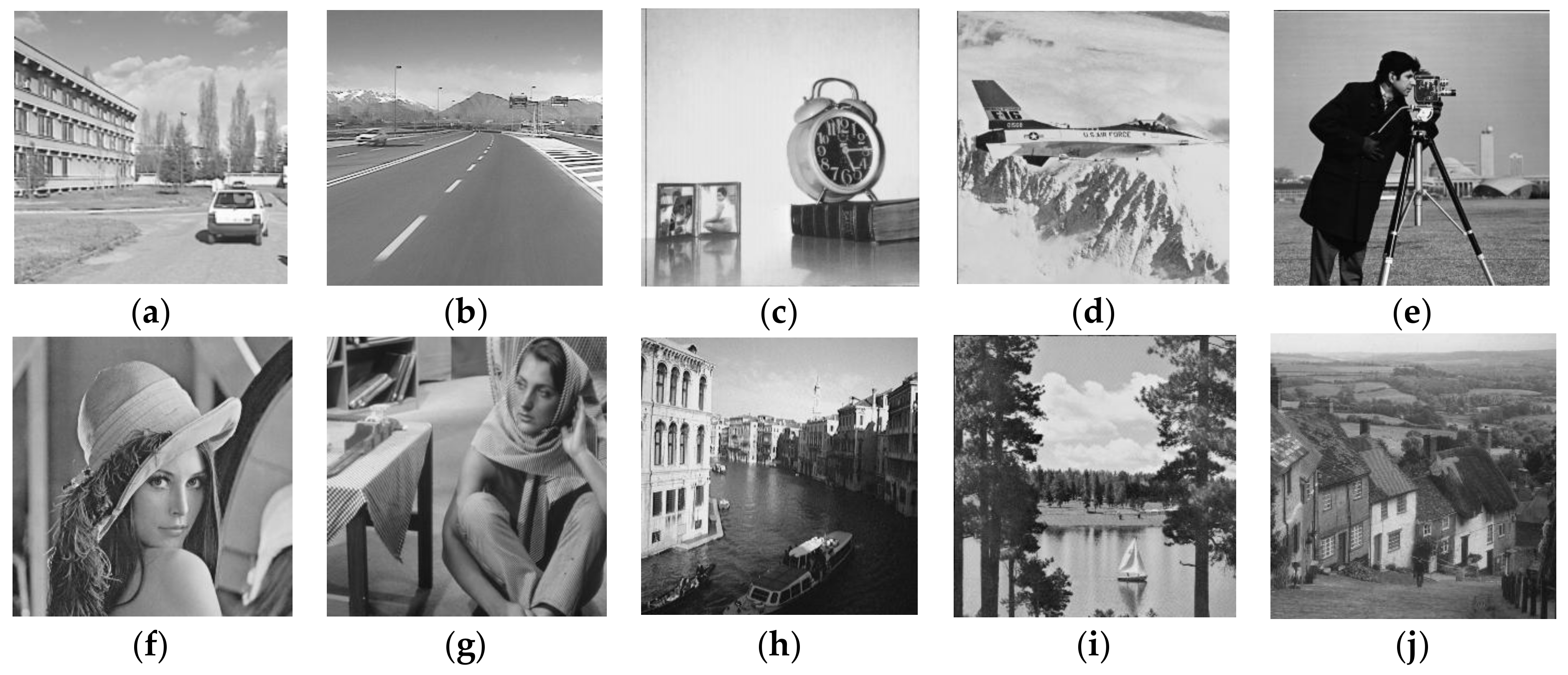
Table 2. The analysis of watermark imperceptibility.
Test ImagesSmooth BlocksTexture BlocksWatermark Capacity (bpp)PSNR (dB)
Car110,51658682.3640.41
Car213,57228122.1742.20
Clock12,36640182.2541.22
Airplane10,94654382.3340.56
Cameraman10,53558492.3640.65
Lena856178232.4839.82
Barbara732190632.5539.52
Venice606210,3222.6339.15
Boat602910,3552.6338.87
Goldhill503811,3462.6938.91
Table 3. Performance comparisons for text addition attack using Lena image.
AlgorithmFPRFNRPSNR (dB) of Recovered Image
Tong et al. [13]0.41%5.41%35.01
Chen et al. [25]0.66%0.93%40.85
The proposed method0.67%045.52
Table 4. Performance comparisons for copy-move attack using Goldhill image.
AlgorithmFPRFNRPSNR (dB) of Recovered Image
Tong et al. [13]0.09%26.13%25.90
Chen et al. [25]0.16%3.25%35.05
The proposed method0.25%0.44%36.13
Table 5. Performance comparisons for collage attack using Car1 and Car2 images.
AlgorithmFPRFNRPSNR (dB) of Recovered Image
Tong et al. [13]0.14%97.33%24.76
Chen et al. [25]0.27%0.14%47.17
The proposed method0.28%047.79
Table 6. Performance comparisons for image deletion attack using Venice image.
AlgorithmFPRFNRPSNR (dB) of Recovered Image
Tong et al. [13]0.22%035.19
Chen et al. [25]0.25%035.21
The proposed method0.30%037.27
Table 7. Performance comparisons for content-only attack using Clock image.
AlgorithmFPRFNRPSNR (dB) of Recovered Image
Tong et al. [13]0119.48
Chen et al. [25]0.44%3.51%36.36
The proposed method0.46%3.32%39.53

