1. Introduction
Centralized electricity generation has dominated modern Urban Energy Systems (UESs) for more than one century. Since the commissioning of the first high-voltage Alternating Current (AC) coal power station in London in 1890, the electrification of UESs has grown rapidly, by covering in 2010 about the 83% of urban areas [
1]. However, during the last decade, the growing pressure towards sustainable and decarbonized energy systems and the deregulation of energy markets have led towards more complex and dynamic systems, which are deeply revolutionizing the foundations of our UESs. In particular, the growing diffusion of prosumers (i.e., local energy consumers and producers [
2]) and the increasing penetration of Distributed Generation (DG) from Renewable Energy Sources (RESs) are posing new challenges to all energy stakeholders, particularly concerning the integration of heterogeneous Distributed Energy Resources (DERs) into the energy landscape. Despite the early mistrust showed by the majority of energy operators concerning the successful integration of RESs into modern UESs, the development of distributed systems based on RESs has been shown to be more a conceptual limitation, rather than an effective technological barrier [
3]. Nevertheless, several socio-technical limitations still exist, mainly concerning the intermittency and unreliability of weather-dependent RESs, the increasing diffusion of energy prosumers, the market stability in dynamic and deregulated systems, and the reliability and resilience of fast-growing and highly dynamic systems with a large share of heterogeneous DERs [
1].
Several research streams have dealt with the upcoming challenges related to the transition towards decarbonized and distributed energy systems, covering different fields: from the application and control of Distributed Electrical Storage Systems (DESSs) for the mitigation of the stochastic behavior of RESs [
4,
5,
6,
7], and the development of innovative control approaches for the operation of Smart Grids (SGs) and micro-Grids (μGs) [
8,
9,
10,
11], to the application of transactive Demand-Side Management (DSM) schemes [
12,
13,
14,
15] and the design of advanced measurement systems [
16,
17]. All these studies resulted in a significant reformulation of the fundamental concepts of current energy systems, remarking the need for a radical shift from the current centralized management of energy systems towards distributed intelligence and Holonic Multi Agent Systems (HMASs) [
1,
2] supported by a proper Information and Communication Technology (ICT) infrastructure [
18]. Following this research trend, in this paper we investigate how the concept of Virtual Power Plant (VPP) can be adapted to fulfill the requirements of emerging UESs with an increasing presence of active prosumers participating in advanced DSM schemes.
The remainder of the paper is organized as follows. In
Section 2, the theoretical background of the study is introduced by focusing on Virtual Power Plants and Demand-Side Management in Urban Energy Systems. In
Section 3, the proposed VPP architecture is presented and then discussed in the following Sections. In
Section 4, the communication infrastructure of the VPP is described and its main features are discussed, while in
Section 5 the structure of the energy management system is presented by drawing attention to active demand-side response capabilities and proposing a suitable optimization model. Finally, in
Section 6 the control capabilities and provisioning of ancillary services are described. In conclusion, in
Section 7 the main contributions of the paper are summarized and the final remarks are presented.
2. Theoretical Background
During the last decade, urban energy systems have undergone a significant change, evolving from centralized and hierarchically structured systems to distributed systems characterized by an increase of complexity in both terms of the number and type of resources and of the different actors involved in the energy supply chain.
Different concepts and innovative approaches have been proposed in the scientific literature. The main research streams on the matter have been recently discussed in [
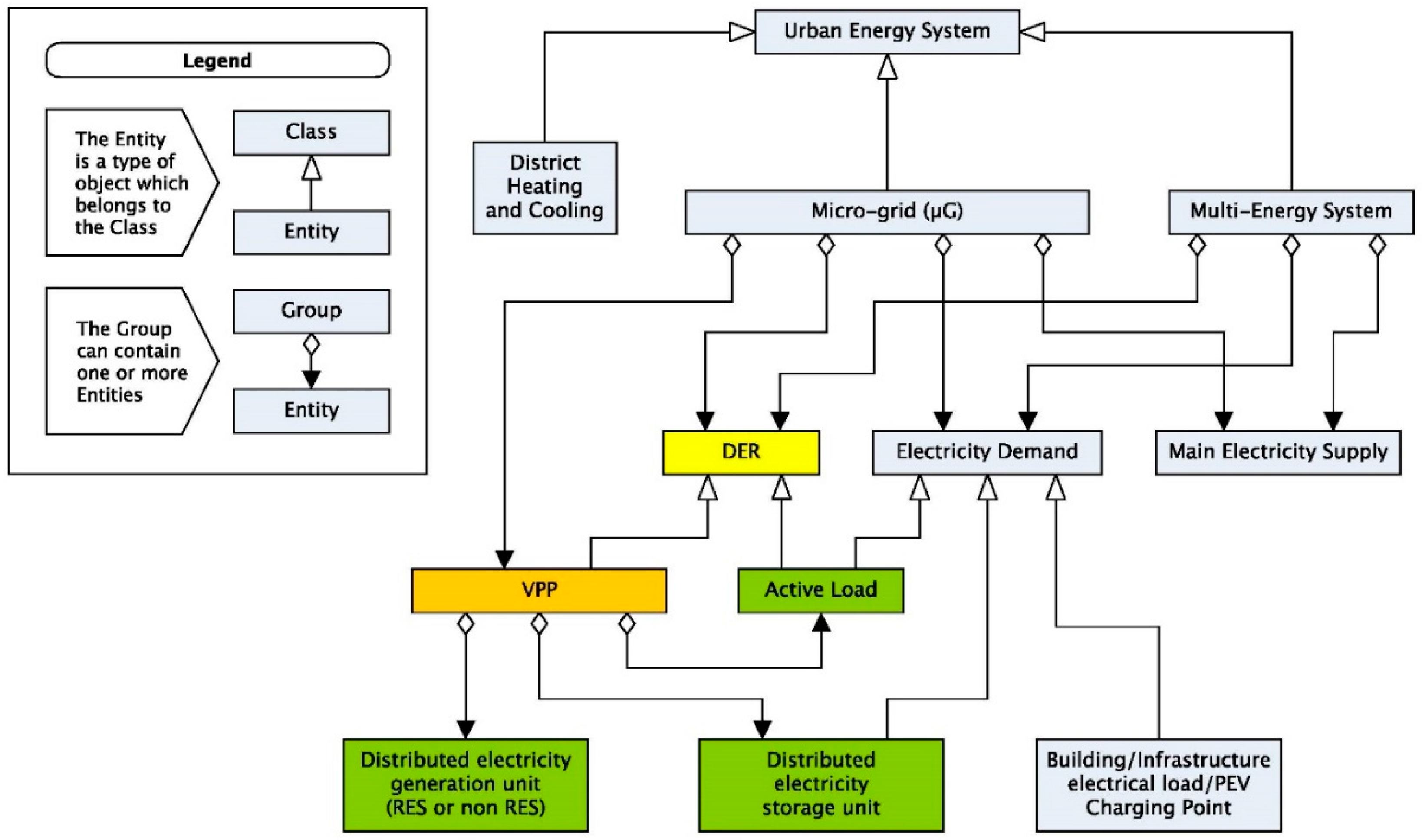
1], which presented a comprehensive analysis of the current definition and evolution trends of UES concepts by describing the relationships between individual entities and the related interoperability requirements. According to [
1], the nature of emerging concepts in present UESs can be described by the Unified Modeling Language (UML) class diagram depicted in
Figure 1, which summarizes the current understanding of electrical energy resources in UESs based on the almost 500 sources reviewed by the considered study.
As shown by the diagram of
Figure 1, VPPs are expected to play a central role in future UESs by providing improved automation and control capabilities in smart grids through the aggregation and virtualization of dispersed DERs, including power generators, storage units, and active loads. Several works in the literature demonstrated the highly beneficial contribution of the VPP concept for the optimal control of heterogeneous DERs in UESs [
19,
20,
21,
22,
23,
24] by also emphasizing the key role of DSM schemes for the successful implementation of VPP management strategies. However, as we also discuss in the following subsections, research to date typically considers VPPs as a generalized abstraction of DERs owned by different stakeholders, and the proposed control and DSM strategies are still designed according to the centralized control paradigm [
1]. In this perspective, the distribution system is still granted the role of central controller rather than that of supervisor and coordinator of the different transactive actions among the involved stakeholders.
Starting from this critical analysis, in this paper we propose a conceptual VPP architecture in which the control perspective is moved from the system (or supervisory) level to the single prosumer’s level, who participates in advanced DSM schemes by offering flexible power profiles through the aggregation of owned DERs, including generators, storage units, and controllable loads.
2.1. Demand-Side Management
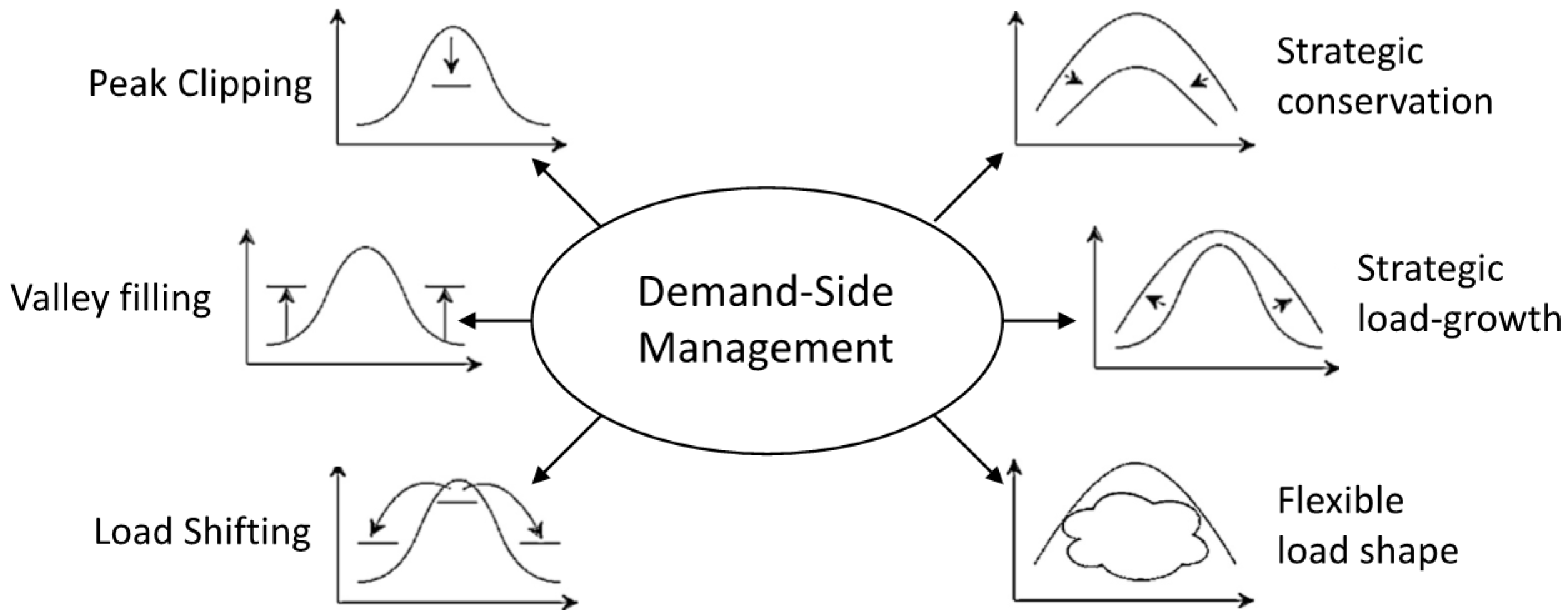
The concept of Demand-Side Management embraces all of the activities, implemented by utility operators, which are designed to influence or directly modify the power profiles of electricity customers in order to ensure a more reliable and efficient operation of electrical grids. The DSM concept is not new in the landscape of UESs. The application of DSM models, in fact, has been proposed since the early 1980s by energy utilities to influence the load profiles of electricity customers [
25]. According to [
25], the main objectives of DSM can be classified into six different categories as shown in
Figure 2: peak clipping, valley filling, load shifting, strategic conservation, strategic load-growth, and flexible load shape. The main objectives depicted in
Figure 2 can be further grouped into two main categories: load management actions and strategic conservation actions.
Load management refers to those actions that are intended to modify the power profile of end-users at specific times of the day or periods of the year (e.g., seasons), and encompasses peak clipping, valley filling, load shifting, and flexible load shape. Peak clipping, also known as peak shaving, is one of the most important objectives of DSM. The aim of peak clipping is the reduction of system peak loads, and is generally required in case of scarce (or even loss of) power capacity, or in case of high incremental costs in the production of electricity. Peak clipping can be either obtained by the direct or indirect reduction of the power consumption of customers, respectively, by means of control signals or price signals. Another form of reduction of system peak loads is represented by load shifting, which aims to shift the power demand of end-users from peak times to off-peak times by means of price signals or through energy storage systems. Valley filling is, conversely, the goal of increasing the power demand of customers in time periods where long-run incremental costs are less than the average price of electricity. Finally, flexible load shape can be considered as the combination of the three main load management modes, and aims at a more complex and flexible modification of the power demand patterns of end-users.
Strategic conservation is the group of DSM objectives that aims at a general modification of energy consumption by means of utility-stimulated programs. This group includes: strategic conservation and strategic load-growth. Strategic conservation represents the goal of reducing the consumption of electricity (e.g., through energy efficiency actions), while, conversely, strategic load-growth aims at increasing the power consumption of end-users following economic development policies or economies of scale.
The DSM concept has evolved rapidly during the last decade, mainly due to the improved communication and control capabilities offered by modern ICT solutions [
13]. Even though the main objectives of DSM introduced in [
25] can still be considered actual, the ways researchers, utilities, and market operators envisage the implementation of such objectives have changed significantly. In particular, the load management concept has evolved into the so-called Demand Response (DR). In [
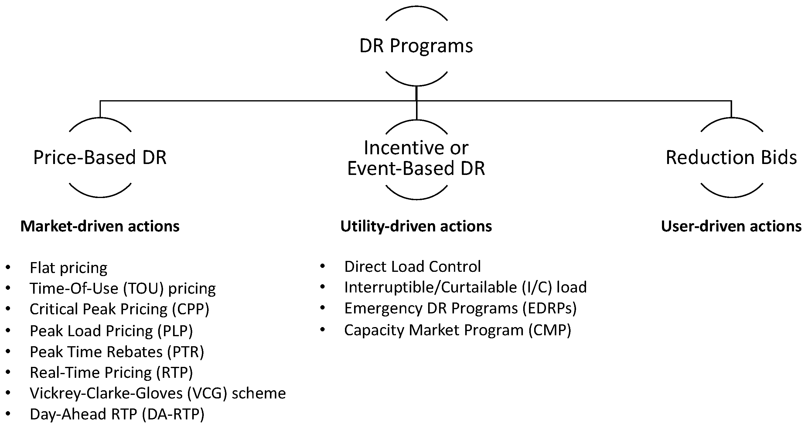
14], Siano proposed two interesting metrics for the classification of current DR schemes based on the entity that initiates the DR request and on the objective of the request.
Three different entities are typically involved in the application of DR schemes: the electricity market, which pursues stakeholders’ benefits, the utility, which is primarily engaged with operation and reliability issues, and customers, who mainly care for electricity bills and quality of service. Accordingly, three group of DRs are identified, based on the party that initiates the demand reduction action, as depicted in
Figure 3: price-based DRs, incentive or event-based DRs, and reduction bids. In price-based DRs, the market initiates the DR event by offering customers static or dynamic pricing schemes to influence the load profiles of end-users. In incentive or event-based DRs, the utility sends specific DR requests (typically active power limitations), and customers are offered fixed or time-varying payments in case of acceptance and execution of the given request. In this case, penalties are also considered in case of acceptance but eventual failure to accomplish the DR request. In reduction bids, customers initiate the DR request and send demand reduction bids to the utility by offering an available demand reduction capacity and the requested price.
Alternately, DR schemes can be classified into two more groups, according to the objective of the DR request: Market DRs and Physical DRs. While Market DRs—which include real-time pricing schemes and incentive-based schemes—are driven by economic factors, Physical DRs (which include grid management DRs and emergency signals) are mainly related to reliability requirements.
It is evident that the implementation of advanced DR schemes, particularly if involving the active participation of end-users and small DERs, is central for the management and control of modern UESs. However, as remarked by authoritative studies, such as (but not limited to) [
1,
2], the formulation of DR schemes is still rooted in centralized mechanisms, where supervisory controllers are enabled to remotely control single consumers’ electrical equipment by means of hierarchical structures [
26].
We argue that, in this case, the hierarchical approach could be successfully replaced by exploiting the possibility that end-users would independently respond to specific DR requests by modifying their net power profiles through the use of a local VPP able to implement the combined control of their owned DERs (such as photovoltaic systems or wind turbines, controllable loads and storage systems).
2.2. Virtual Power Plants
A Virtual Power Plant is an aggregation of physical devices (dispatchable and stochastic generators, storage units, and controllable or flexible loads) that forms a virtual entity that interacts with supervisory levels (usually μG controllers) to provide improved monitoring and control functions over multiple DERs [
27]. VPPs are already mature and widely used instruments for the control of DERs in μGs and SGs, and the concept alongside virtualization has been recognized to be highly beneficial for the development and control of future UESs [
19,
20,
21,
22,
23,
24]. However, their implementation and architectures are still rooted in the centralized control paradigm, where central control units are allowed to take the full control of low-level resources.
In [
28], a meta-heuristic algorithm, the Imperialist Competitive Algorithm, is used as VPP control strategy to minimize the total system costs of a collection of several DERs, including RES generators, storage units, and controllable loads, over a time horizon of 24 h. The aim is to optimize the operation costs of DERs installed at different points of the distribution network by collecting resources which are owned by different stakeholders and that are usually dispersed throughout the grid. DSM schemes in this case are also considered, but their implementation is still designed according to the centralized control paradigm, where a central intelligence unit (hosted by the utility) is responsible for the computation of the optimal working point of all of the supervised DERs.
In [
29], a hierarchical structure of VPPs is proposed for the management of different aggregations of power generators, storage units, and flexible loads, by introducing the role of the VPP Operator (VPPO). The VPPO, who may be an independent operator or the distribution system operator, is responsible for the management of the supervised VPPs and implements the coordination with market and utility operators. The control of DERs in each VPP is operated by means of distributed intelligence devices installed at the local level, while the related control functions are computed at the VPPO level. DSM schemes are also taken into account in the form of both transactive and price-based actions. It is worth noting that, again, this architecture is ruled by a centralized control perspective, where operational planning strategies are predominant with respect to the prosumers’ decisions.
The specific application of DR schemes in the context of a VPP aggregating loads and RES generators in a distribution grid has been proposed in [
30]. In this case, single customers are required to promote DR bids on candidate load profiles, and an independent operator is responsible for the final selection of individual profiles by pursuing the optimization of total system costs. Similarly to [
30], in [
31] a bidding strategy for the operation and management of a VPP is proposed, by considering DR strategies and RES uncertainty. In both of the proposed studies, operational plans and optimization strategies are computed at supervisory levels by considering the aggregated DERs only as dispersed generation or consumption units with limited decision capabilities.
Even though this approach can be considered reasonable for large RES installations, such as large wind farms or Photovoltaic (PV) plants (with capacities in terms of hundreds of kW), which are mainly used for bulk electricity generation and directly participate in wholesale electricity markets [
32], we argue that its application for small DERs is at least doubtful. Small residential DERs (such as small PV or DESSs, with capacities in terms of few kW) are in fact mainly intended for local energy generation and consumption [
33] and are usually involved in feed-in tariff schemes [
34], which reward the amount of energy produced. For this reason, it is apparent that the direct control of small residential DERs by means of centralized systems would inevitably collide with the economic interests of such users [
35,
36]. Moreover, the centralized management approach requires an exhaustive representation and complete logical formulation of the supervised physical grid, thus the result is scarcely flexible in the face of the dynamic changes observed in modern UESs.
3. The VPP Architecture
The proposed VPP architecture has been conceived for the management and the dynamic integration of active prosumers participating in advanced DR programs. With respect to the classical VPP approach, which mainly considers the aggregation of several DERs owned by different stakeholders (i.e., end-users, utilities, and independent electricity producers) into a single virtualized entity [
1,
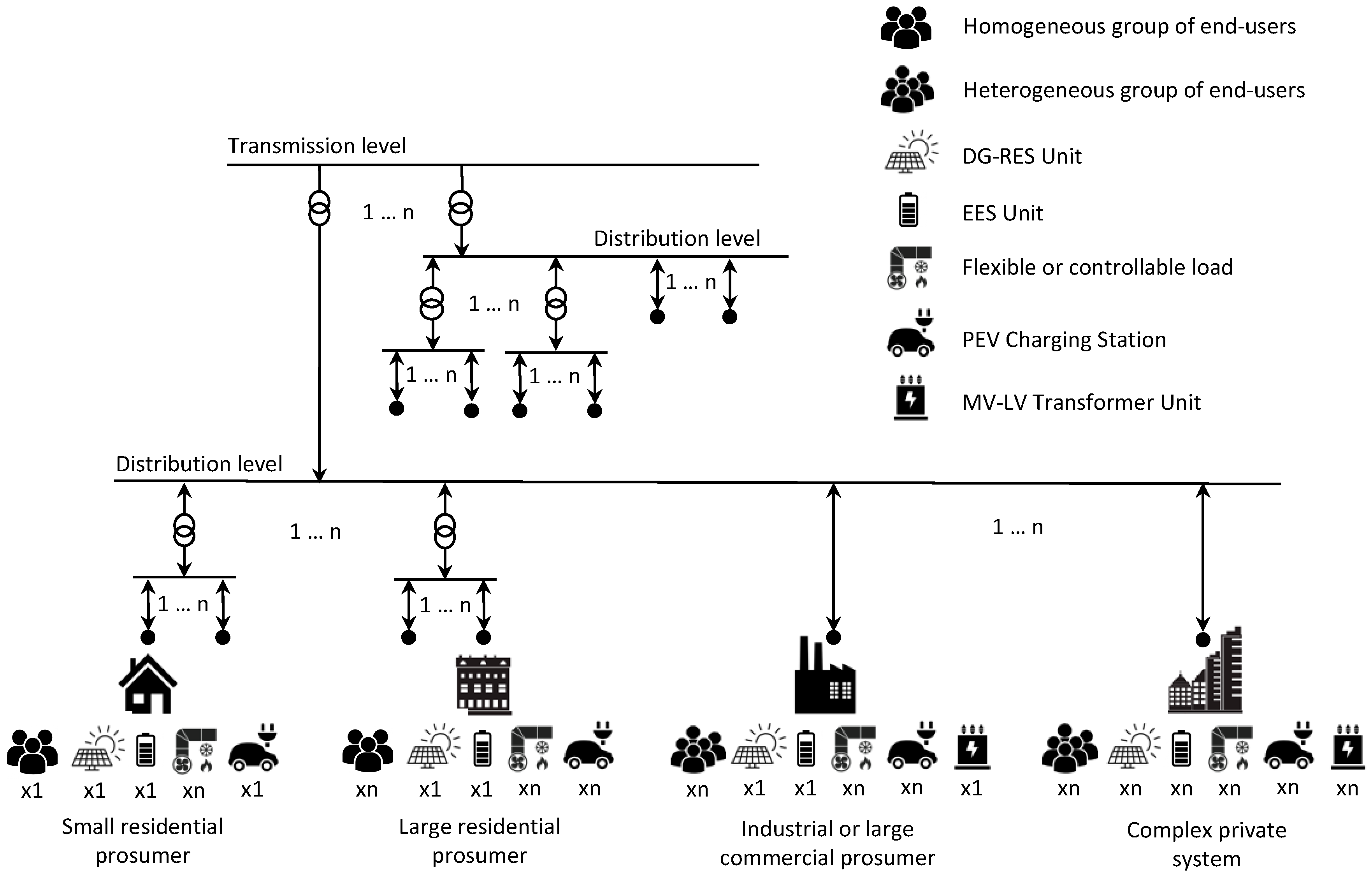
8], the domain of the herein presented VPP architecture is limited to the physical domain of single users. According to this approach, each VPP aims to virtualize all the DERs that are connected to single nodes of the electrical grid, i.e., to single Points of Delivery (PODs). As depicted in
Figure 4, VPPs thus represent an aggregation of all the energy assets of users at each POD of the electrical grid.
For each node of the electrical grid, different possible aggregations of DERs are considered, including RES-based generators, Electrical Energy Storage (EES) units, flexible and controllable loads (e.g., heating and cooling systems, lighting systems, and controllable appliances), Plug-in Electric Vehicle (PEV) charging stations, and Medium Voltage (MV) to Low Voltage (LV) transformer units. It is assumed that different combinations of DERs can be potentially connected to each node of the grid depending on the type of prosumer. As shown in
Figure 4, the diversity and number of DERs, as well as the diversity and number of end-users, define the type of prosumer, here classified as: small residential user, large residential user, industrial or large commercial user, and complex private system. Small residential users consist of a single group of homogeneous end-users (e.g., a family), with a small DG unit (e.g., a PV power plant), in terms of few kW, domestic appliances, and possibly a domestic wall box. Large residential users consist of multiple groups of homogeneous end-users (e.g., more families), with a small- to medium-size DG unit, up to 100 kW, several domestic appliances, and multiple PEV charging stations. Industrial or large commercial users consist of multiple groups of heterogeneous end-users (e.g., employers, customers of commercial activities, and others), and are equipped with a medium-size DG unit, typically more than 100 kW, at least one MV to LV transformer unit, several types of loads, and multiple PEV charging stations. Complex private systems consist of multiple groups of heterogeneous end-users, and are equipped with multiple small to medium-size DG units, multiple MV to LV transformers, several types of loads, and multiple PEV charging stations.
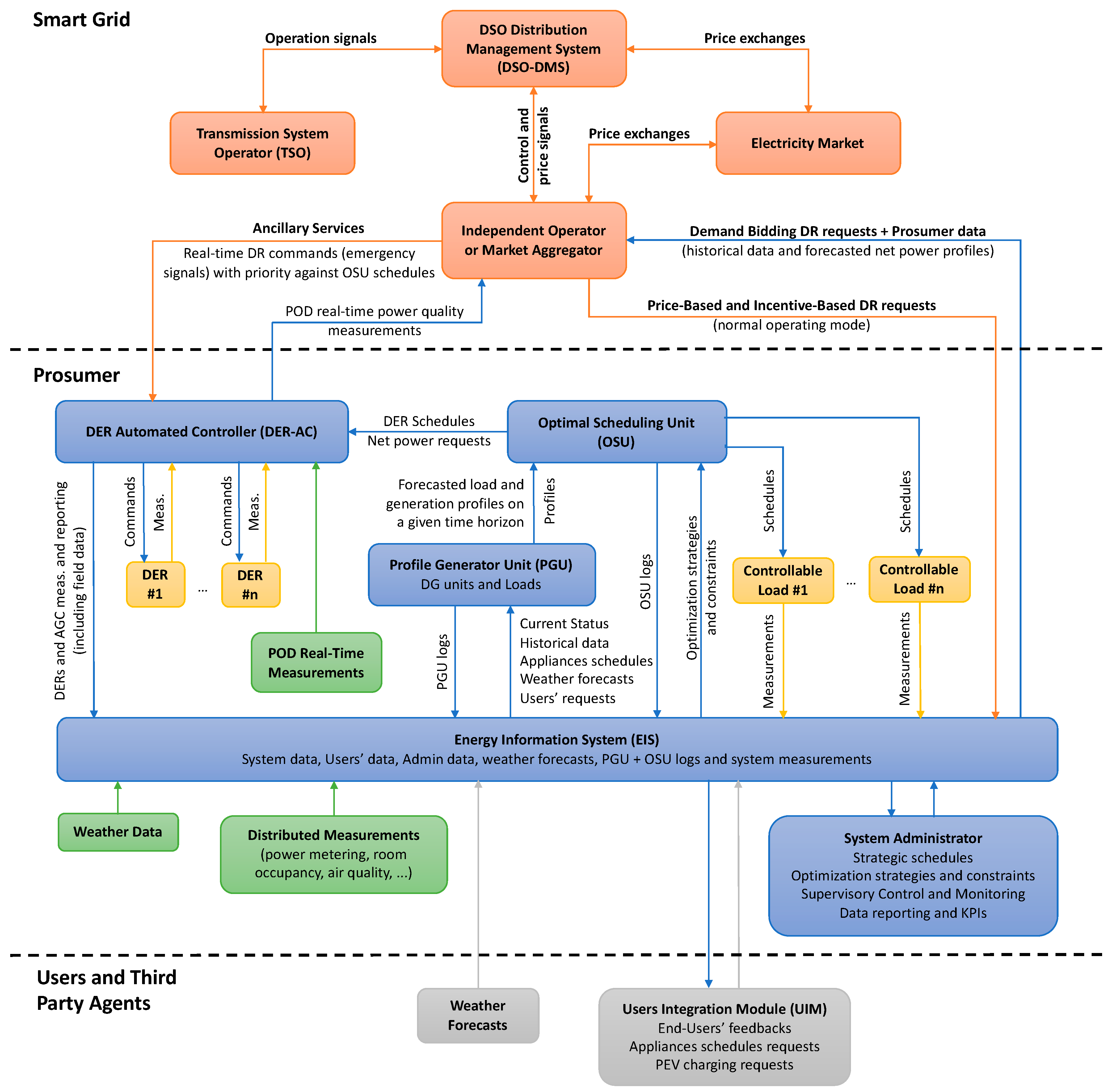
The virtualization of each prosumer, at each node of the distribution grid, is provided by the VPP architecture schematically described in
Figure 5, which defines all the agents involved in the VPP architecture.
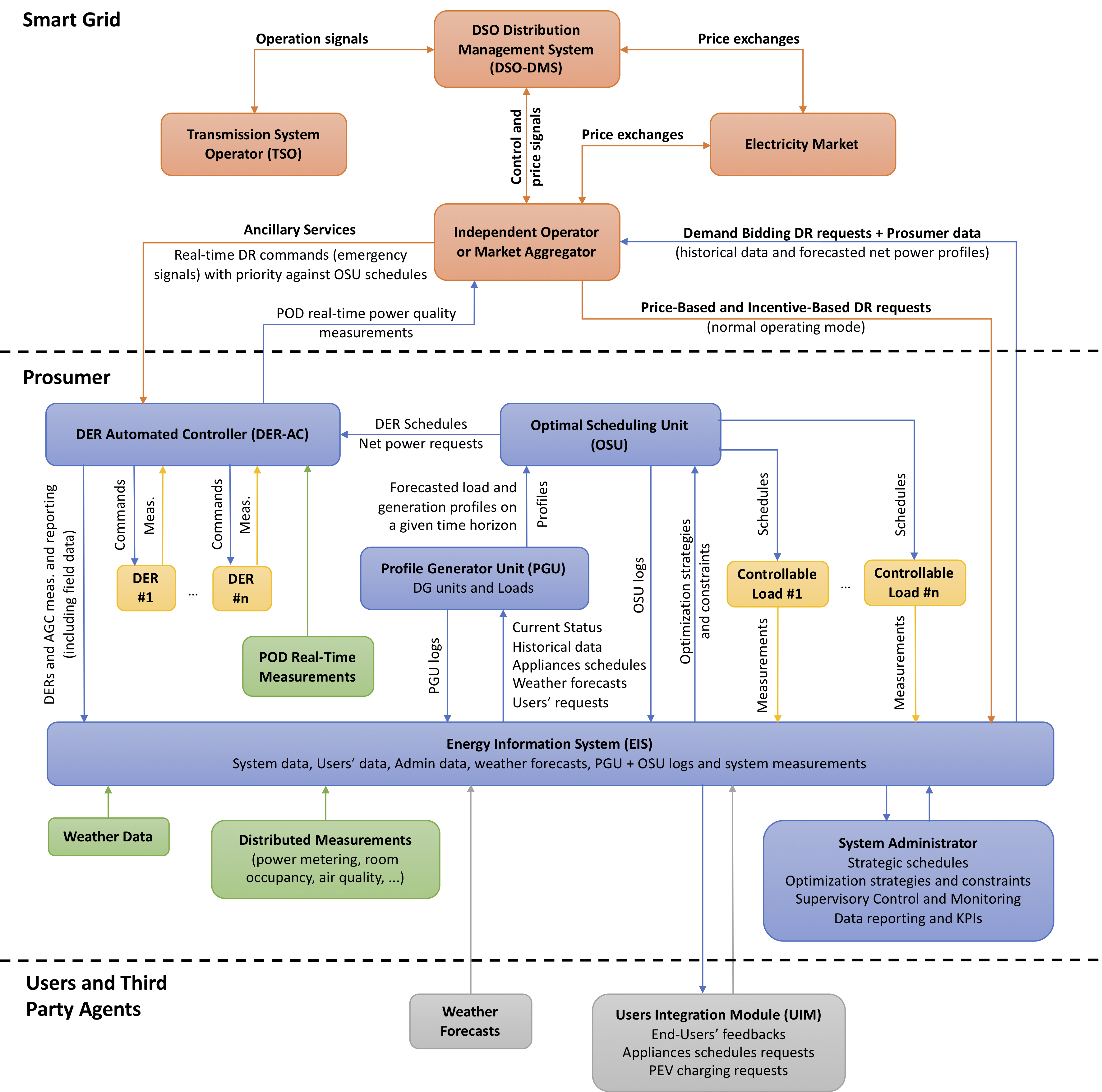
Three different domain levels are defined in the system architecture, namely: the Smart Grid domain, the prosumer domain (i.e., the VPP domain), and the third-party domain. The Smart Grid domain includes all the agents and entities involved in the management and control of the electrical grid, such as the Distribution System Operator (DSO), the Transmission System Operator (TSO), the electricity market, independent operators, and market aggregators. The prosumer domain contains all the energy assets owned by the prosumer, which represent an economic value in terms of consumption, production, reliability, maintenance, and quality of service. This domain also includes the system administrator, who is responsible for the strategic management of the system, by defining operation constraints, strategic schedules, and optimization objectives. Finally, the third-party domain embraces all the entities that are not included in the prosumer and Smart Grid domains. These can be generic entities which provide services to the prosumer (such as weather forecast services) or end-users, such as families in private homes or large residential buildings, PEV owners (who may not belong to the supervised system, i.e., they may be just occasional users), customers of large commercial buildings, or students in a university campus. End-users can interact with the system by sending requests related to the use of energy resources (e.g., PEV charging requests) or feedbacks about the quality of service (e.g., about the perceived comfort), and by receiving information on the acceptance or denial of specific requests, or about the availability of services and resources (e.g., PEV charging stations or smart-plugs), and on the state of the system, with the purpose of improving end-users’ awareness about energy savings.
Three different types of agent are used in the architecture: physical agents, communication agents, and logical agents. Physical agents are used for the abstraction—in terms of estimation of the state and supervisory control functions—of the physical assets, such as switches, generators, and loads. In particular, each agent, designed according to the service-oriented approach, contains the knowledge base required for the proper virtualization of the related physical component. Physical agents are typically installed in distributed Intelligent Electronic Devices (IEDs), such as gateways or local controllers. Communication agents are used to gather data from the heterogeneous distributed measurement devices installed in the user’s domain (that may be physical instruments, i.e., sensor devices, or virtual instruments, such as gateways or other IEDs) and for the exchange of information between all of the agents in the system architecture. Communication agents, for instance, are used for communication between the VPP and the Smart Grid (e.g., for DR requests) or end-users. Logical agents are intended for the intelligent management of the VPP. Their functions are related to the optimal and strategic management of the prosumer’s energy assets, including the optimal scheduling of controllable and flexible loads, the control of RES generators and storage units, the active participation in DR schemes, and the monitoring and strategic management of the quality of service towards end-users. Logical agents, for instance, are those in charge for the forecast of day-ahead power profiles of DER units.
Finally, three main automated and intelligent systems are considered in the VPP architecture: the Energy Information System (EIS), the Energy Management System (EMS), and the DER Automated Controller (DER-AC).
The EIS is the core of the information system of the VPP. It collects data from all the communication agents (system data, users’ data, weather forecasts, system logs, DR requests, etc.). It provides communication services to all the agents interacting with the system (either internal or external), and it is also responsible for the time synchronization of distributed measurements. The detailed discussion of the ICT structure of EIS will be provided in
Section 4.
The EMS is responsible for the management and optimization of the prosumer’s energy assets supervised by the VPP. Two main groups of supervised assets are considered in the proposed architecture: controllable loads and DERs. Controllable loads include all the appliances, devices, and systems whose electricity demand can be controlled by the prosumer in terms of power consumption (e.g., PEV charging stations), time or profile of use (e.g., air conditioning systems), and availability (e.g., smart-plugs). Conversely, DERs are all those energy assets intended to balance (at least partially) the electricity demand of loads. DERs typically include RES generators (e.g., PV or wind generators) and ESSs. PEV charging stations offering Vehicle-to-Grid (V2G) services may also be included in this group. DERs are also entitled to offer the DSO (directly or through independent operators) ancillary services, such as the limitation of active and reactive power at POD level. A detailed description of the architecture and functions of EMS will be provided in
Section 5.
The DER Automated Controller is responsible for the supervisory control of all the DERs virtualized by the VPP as defined in
Figure 5. It interacts with the EMS agent, from which it receives DER schedules or active power constraints, and with the DSO or Independent Operators (IOs), offering ancillary services and real-time measurements on the state of the system. The architecture and main functions of DER-AC will be discussed in
Section 6.
4. Communication Infrastructure
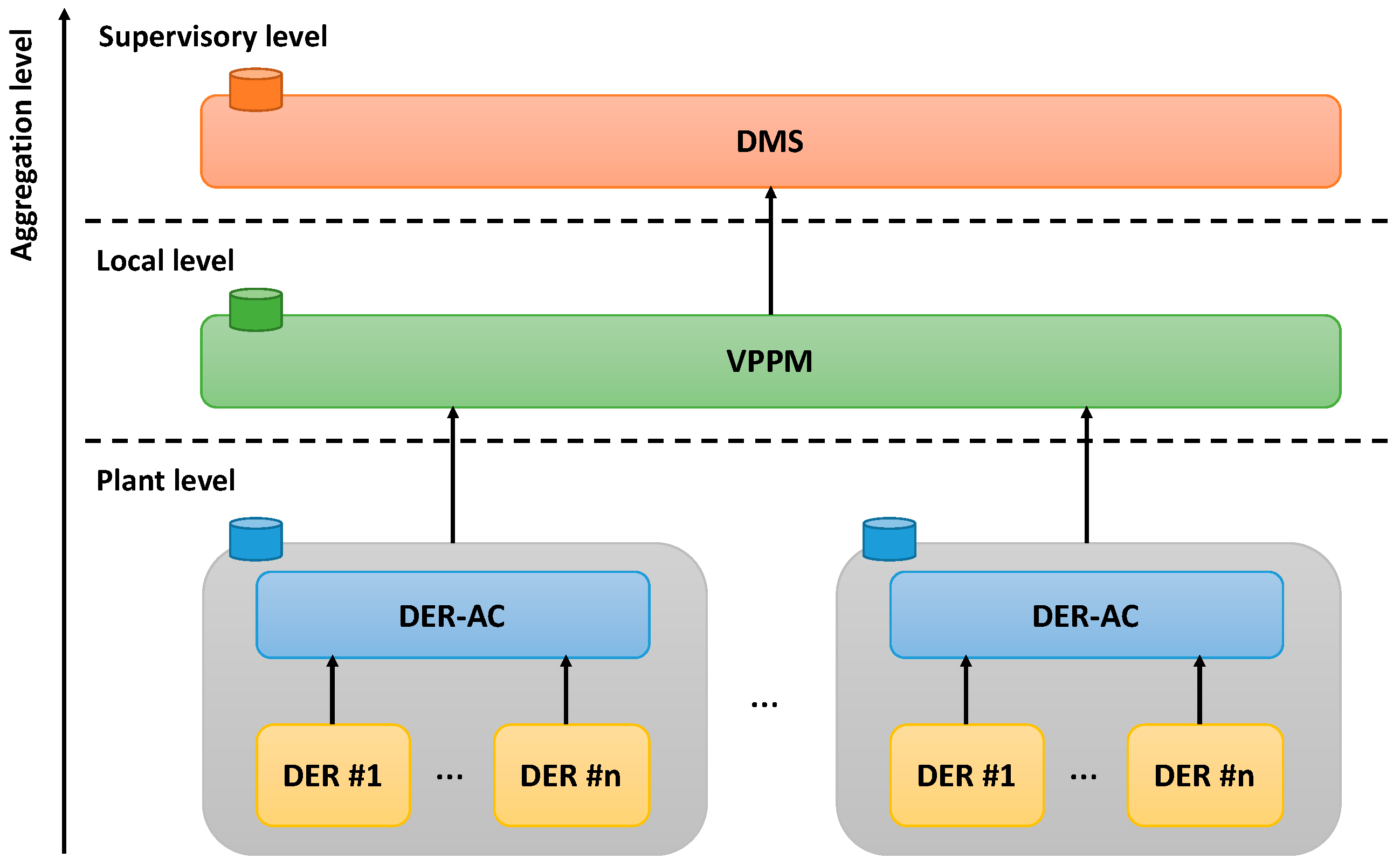
The management of DERs in a VPP requires the monitoring of information from several DER installations, and from sensors monitoring the environmental conditions. Such functionality requires an ICT infrastructure able to support the aggregation of data and the virtualization of DERs. A possible architecture of the communication infrastructure among different VPPs and the distribution network is shown in
Figure 6.
With reference to the schematic of
Figure 6, DERs represent physical devices installed on the local power grid, and they are part of the plant-level communication layer. PV inverters or Battery Energy Storage Systems (BESSs) are examples of DER units. Each of these devices is responsible for the monitoring and transmission of data measured at the plant level. DERs should be connected with the DER-AC by means of a field-bus communication to allow the DER-AC to implement control functionalities. In addition, the DER-AC is responsible for the first level of aggregation (data virtualization) with respect to the DSO-DMS or to the IO-DMS. The DER-AC aggregates data provided by DER units, and estimates the total average power and the total energy produced by the supervised DER units over a predefined interval as well as the total available energy in storage systems (i.e., considering that more BESSs can be installed at the same plant level). In normal operation mode, the frequency of data transmission is limited to a sample every few minutes. A typical value is in the range of 5 to 15 min [
11]. The total amount of data transmitted per each node per each transmission is typically less than a hundred bytes. Thus, the communication bandwidth required by the plant-level communication is well within 100 kbps.
The DSO-DMS (or IO-DMS) agent defined in
Figure 5 can be expanded into two parts, as highlighted in the ICT architecture: the Virtual Power Plant Monitor (VPPM) and the Distribution Management System (DMS). The VPPM monitors DERs fed by the same secondary substation or by a section of the distribution grid, which can be assumed to be homogenous from the DSO/IO point of view. The VPPM agent is typically located locally, while the DMS agent supervises the entire distribution grid. The VPPM is responsible for the second level of aggregation, which works both temporally (considering an interval larger than the previous one) as well as spatially (aggregating data from several customers). The communication infrastructure among the VPPM and DER-ACs forms the local level. Finally, the DSO/IO aggregates data coming from several VPPMs in its DMS to improve the state of estimation of the grid and to optimize the energy flows, and forms the supervisory communication level. In both the cases, the total amount of data exchanged is well below 1 Mbps, and no particular latency requirements are needed.
The VPP ICT architecture defined in
Figure 6 requires a communication infrastructure with a proper structure. As mentioned in the previous paragraph, the communication system is organized in three hierarchical levels: the plant level, the local level, and the supervisory level. Each communication level has its specific requirements in term of bandwidth, latency, time synchronization, and cyber-security. The plant level connects all the devices installed on the field (such as inverters, storage systems, energy meters, and sensors) to the DER-AC, which performs the monitoring and the control functionalities. Typically, this level does not require communication technologies able to provide large bandwidth, while the real-time behavior (i.e., deterministic latency) is a strict requirement due to the control functionalities performed at this level. In the literature, several solutions have been proposed, including the use of traditional wired fieldbuses (e.g., Modbus RTU over RS-485 [
37], CANopen over CAN-bus [
38], and Modbus TCP over Ethernet [
39]), used to connect electrical machines, wireless connection (e.g., IEEE 802.11ac [
40]), and Power Line Communication (PLC) with network management provided by Software Defined Networking (SDN) [
41]. In addition, a time synchronization service is required by the plant level in order to be able to properly refer each measurement provided by the devices in the plant with respect to the Universal Time Coordinated (UTC). Since the time synchronization requirement is almost relaxed (i.e., time synchronization accuracy in the order of seconds is more than enough for a large part of the power applications), general purpose time synchronization services, such as the Network Time Protocol (NTP), are typically adopted [
42].
Locally, the data aggregated by DER-ACs, each of them representing a single POD, are then transmitted to the local VPPM aggregator. The total amount of data transmitted over the local-level communication depends on the number of total DER-ACs from which the VPPM aggregates data, typically in the order of tens. Thus, the bandwidth requirement is well below 1 Mbps. The local level has also limited requirements both in terms of latency as well as in terms of time synchronization. The supervisory level, connecting the VPPM with the DSO/IO-DMS, shares a large part of these requirements. The main limits, in both cases, are represented by the installation and management costs of a communication infrastructure over the distribution grid. Therefore, these levels are deployed using the already existing communication infrastructure, such as telco network, integrated with technologies, such as PLC or Wireless, with limited installation costs. The performance of such an approach has been validated on a working pilot project on the distribution grid and the results are presented in [
43].
In the current analysis, the focus is on the plant-level communication infrastructure. The characterization of a pilot plant adopting such approach is provided in [
44]. As indicated in [
44], a proper use of existing communication solutions makes the application of the proposed VPP approach technically feasible and economically sustainable.
5. Energy Management
The Energy Management System of the VPP is made up of two main components: the Profile Generation Unit (PGU) and the Optimal Scheduling Unit (OSU).
The PGU is responsible for the computation of the power profiles of all of the DER units and loads supervised by the VPP, including DG units, ESS units, and both controllable and uncontrollable loads (i.e., the aggregated power profile of all uncontrolled and unprogrammable loads). Each power profile is defined as the active power produced or consumed by the specific physical entity over a given time horizon (typically 24 h) with a system-defined time step (usually 15 min). For each physical entity, one or more profiles can be generated depending on the possible different configurations of the resource. Air conditioning systems, for instance, may have different feasible demand profiles, depending on the considered scenarios (i.e., comfort level, use of thermal storage, etc.), based on the given weather forecasts, expected room occupancy, and time schedules. For each power profile (which corresponds to a specific use of the device), a command profile (or schedule) is also determined, containing all of the control parameters required by the physical entity to meet the desired power profile. Power profiles are determined for all of the supervised entities by taking into account the users’ requests, weather forecasts, strategic schedules and constraints (set by the system administrator), historical data (used by machine learning algorithms), and current measurements from distributed sensors (i.e., current weather data, room occupancy, state of charge of EES units, etc.).
The OSU is responsible for the computation of the optimal working point of the VPP. It collects the power profiles and related schedules from the PGU, optimization constraints and objectives from the systems administrator, and DR requests from the DSO or IO (Price-Based and Incentive-Based requests in normal operating mode). After the optimal working point is determined, the related command profiles are sent to the local controllers by means of specific communication agents.
5.1. Active Demand-Side Response
Four different DR requests can be managed by the VPP architecture: Price-Based DRs, Reduction Bids, Incentive-Based DRs, and Event-Based DRs. The first three DR requests, usually applied during the normal operating mode of the grid, are managed by the EMS, while Event-Based DRs—which are usually sent during critical events or emergencies—are managed by the DER Automated Controller as discussed in
Section 6.
Price-Based DR requests can be sent by the DSO or by DR aggregators. DR requests are collected by communication agents of the VPP and sent to the Optimal Scheduling Unit, which uses the price information for the computation of the optimal working point of the VPP. At the same time, Reduction Bids can be generated by the OSU and sent to the DSO or to DR aggregators. Finally, Incentive-Based DRs are usually sent by the DSO or the IO by requiring active power limitations (i.e., upper and lower bounds) at the Point of Delivery of the prosumer. Incentive-Based DRs are sent to the OSU in terms of power constraints over the time period specified by the DR request along with the economic value of the proposed incentive. If an optimal solution is determined, the DR request is accepted by the EMS, and the related optimal schedules are sent to the programmable DERs and loads. In addition, the active power limitations defined by the Incentive-Based DR are sent to the DER-AC, which performs the active power control of the supervised DERs in order to ensure that, in case of unexpected variations in the forecasted DER profiles, the required constraints set by the DR request can be accomplished.
5.2. Optimization Model
In the following, we propose a Mixed-Integer Linear Programming (MILP) formulation for a general optimization model that can be implemented in the OSU. The use of MILP models is a common practice in energy management optimization systems [
45,
46] thanks to their easy implementation in modern computational systems. In fact, this kind of mathematical program can be nowadays solved quite efficiently (despite their theoretical complexity) by means of black-box solvers, such as
Cplex [
47] or
Gurobi [
48].
Let us define as the set of time slots composing the considered optimization time horizon, as the set of loads characterized by power consumption profiles, and as the set of generators characterized by power generation profiles. Moreover, we call () the set of feasible working profiles for each load (). For each time slot , () represents the power required by (available from ) working with profile (), represents the comfort level associated with working with profile , is the unitary price of the power purchased from the grid, and is the unitary gain deriving from the power fed to the utility. The maximum power than can be taken from (fed to) the grid, if no DR requests are considered, in the time slot is (), and the external non-electric costs associated with using profile of (profile of ) is (). Finally, is the unitary incentive granted to the power generated by .
The participation in DSM schemes is modelled by defining as the set of DR requests provided to the prosumer, where and are the sets of DR requests associated with the maximum and minimum values of power that can be taken from the grid, respectively, whereas and are the sets of DR requests associated with the maximum and minimum values of power that can be fed to the grid, respectively. Moreover, let () be the set of time slots which correspond to the temporal domain of the demand-response . In each time slot , () represents the minimum power that can be taken from (fed to) the grid according to DR request (), whereas () represents the maximum power that can be taken from (fed to) the grid according to the DR request (). Finally, is the total incentive paid to the prosumer if the negotiable profile is respected for .
The decision variables of the model are defined as follows:
() represents the power that must be taken from (fed to) the grid in the time slot ;
() is a binary variable taking value 1 if profile () is chosen for (), and 0 otherwise;
() is a binary variable taking value 1 if the power taken from (fed to) the grid is strictly positive in time slot , and 0 otherwise;
is a binary variable taking value 1 if, in time slot , the system complies with the request , and 0 otherwise;
is a binary variable taking value 1 if request is satisfied, and 0 otherwise.
In the following, the mathematical formulation of the model is defined:
Equation (1) defines, for each time slot , the power ( that must be taken from (fed to) the grid to satisfy the internal power requirements. Given a time slot , Equation (2) defines the total load required by profile-able systems, whereas Equation (3) defines the total power provided by the VPP generators. Moreover, constraints (4)–(6), together with non-negativity and binary conditions on the involved variables (7)–(8), ensure that the power is taken from or supplied to the grid, but not both simultaneously (i.e., during the same time slot). Note that constraints (4) and (5) also ensure the system reliability with respect to the maximum values and . Finally, to achieve feasible schedules, only one profile has to be chosen for each profile-able piece of equipment and for each generator, as stated by constraints (9)–(12).
The DR policy can be tackled by the following constraints:
In particular, constraints (13) and (14) manage the requests of reducing the power taken from and supplied to the grid, respectively. More precisely, when the request is satisfied in time slot (i.e., when ), then and have to be less or equal than the power limitation associated to the request, otherwise (when ) the limitation is represented by the nominal maximum values. Constraints (15) and (16), instead, manage the requests of increasing, respectively, the power taken from and supplied to the grid, ensuring that and are greater than or equal to the minimum power associated with the request if satisfied in time slot . Finally, constraint (17) states that a request is totally satisfied () only if is satisfied in all of the time slots involved in the DR request. Constraints (18) and (19) are binary conditions on variables.
The optimization is guided by the objective function defined in (20), which aims at minimizing the total VPP systems costs and, simultaneously, at maximizing the comfort associated with the use of the prosumer’s equipment:
As commonly done in the MILP literature [
49,
50,
51], the two conflicting components (costs and comfort) are linearly weighted in the objective function by appropriate coefficients,
and
, respectively, with
. In order to combine equivalent quantities, we introduce a converting factor
representing a fictitious gain for guaranteeing a unit of comfort in time slot
for each piece of equipment
. Furthermore, we can distinguish two extra components within the costs expression: the first one takes into account all the costs and the gains produced by the unconstrained management of the VPP, whereas the second one represents the potential gain produced by the participation to DR requests. Even in this case, the two sub-components are weighted by coefficients
and
, respectively, with
.
6. Control Capabilities and Ancillary Services
The main functions of the DER-AC are to: (i) ensure the monitoring of all the supervised DERs of the VPP, (ii) implement the control schedules and the power constraints set by the EMS, and (iii) provide ancillary services to the DSO or to IOs. While the DER monitoring and communication capabilities are presented in
Section 4, the control capabilities and ancillary services provided by the DER-AC are discussed in the following.
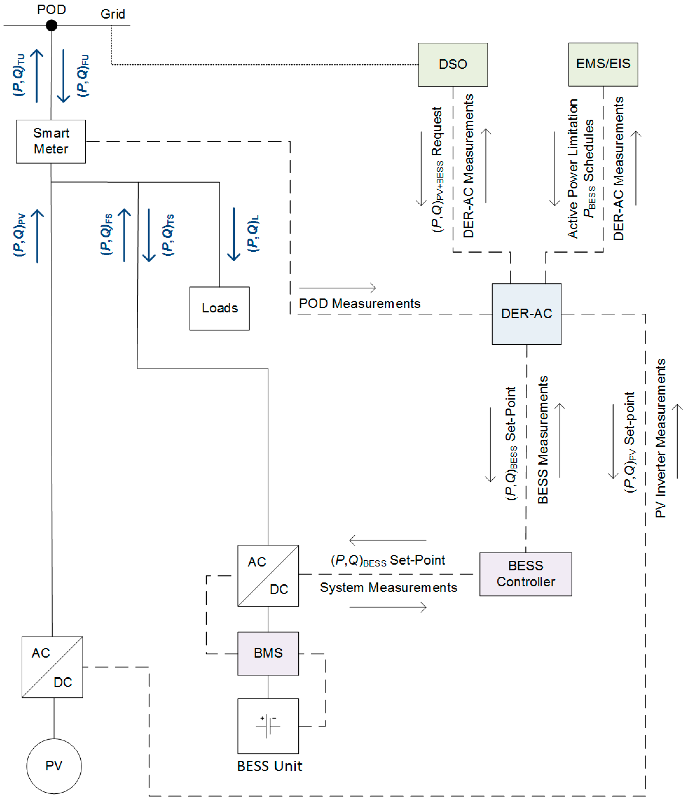
The above-mentioned control capabilities are discussed by referring to the schematic diagram depicted in
Figure 7. This diagram represents the simplified control architecture of the VPP system (i.e., the hierarchical control architecture among the DER-AC and the supervised DERs) in case of a system with a PV generator and a battery storage unit. The power flow measurements in
Figure 7 are reported according to the nomenclature defined in the IEC 61724 standard [
52], where:
P and
Q represent, respectively, active and reactive power flows, PV is referred to the power production of the photovoltaic plant, TU and FU represent the power flows measured at a user’s POD (respectively fed to the utility and taken from the utility), TS and FS are the power flows measured by the BESS controller (respectively fed to the battery and taken from the battery), and L represents the aggregated power consumption of loads.
The DER-AC can operate in two different modes, namely: the normal operating mode and the emergency operating mode. During the normal operating mode, the DER-AC implements the management decisions of the EMS, while in the emergency mode (i.e., when emergency signals are sent by the DSO/IO-DMS), the control signals provided by the EMS are discarded, and the DER-AC takes the control of the supervised DERs to match the requirements of the DSO/IO by implementing active and reactive power control algorithms.
During the normal operating mode, the DER-AC operates according to the requirements of the EMS unit. In the case of the system described in
Figure 7, where a single programmable DER is considered (i.e., the BESS unit), the scheduled active power profiles of the BESS unit (
PBESS) are provided by the EMS and forwarded by the DER-AC to the BESS control unit (the BESS Controller in
Figure 7), which, in turn, is responsible for the low-level control of the Battery Management System (BMS) and of its related inverter. If Incentive-Based DRs have been accepted by the EMS optimization process, active power limitation constraints are also provided to the DER-AC to ensure that, in case of unexpected behavior of the PV generator during the time period specified by the DR request, the required constraints can be accomplished. In this case, the DER-AC implements the control of the charge and discharge active power of the battery unit, with priority against the power set-points defined by the BESS schedules, to ensure that the power flows measured at the user’s POD would not exceed the limits defined in the DR request.
If emergency signals are sent by the DSO or by IOs, the management decisions of the EMS are discarded and the DER-AC takes full control of the supervised DERs by providing active and reactive control functions to meet the desired requirements set by the DSO/IO-DMS. The active and reactive power set-points of both the BESS unit and the PV inverter are computed by the DER-AC according to DSO/IO-DMS requests. In particular, in case the amount of power fed to the grid exceeds the constraints set by the DSO/IO-DMS, and the BESS unit is not able to store the excess of power (i.e., the BESS unit has reached its maximum storage capacity), the output power produced by the PV system is reduced by off-tracking the maximum power point voltage of the PV strings.
7. Conclusions
In this paper, we presented a conceptual study on a VPP architecture capable of implementing the management of DERs owned by prosumers participating in advanced DSM programs. Compared to classical VPP architectures, which aim to aggregate and virtualize several DERs dispersed throughout the electrical grid, and possibly owned by different prosumers, the proposed VPP architecture is limited to the physical domain of single users, i.e., to single PODs of the distribution network. According to this concept, the proposed VPP architecture aims to allow the integrated and coordinated implementation of different control and management strategies, including energy management, demand response capabilities, and ancillary services.
With respect to centralized and hierarchical VPP control architectures, in this study the control perspective was moved from the system (or supervisory) level to the single prosumer’s level, who is allowed to independently provide flexible power profiles through the aggregation of multiple DERs, including generators, storage units, and controllable loads. In this case, central distribution management systems are allowed to interact with smart prosumers by applying different DR requests without the need for modelling each energy asset in the prosumer’s physical domain. In addition, this conveyance of “responsibility” from the supervisory level to local levels would also reduce the complexity of distribution grid management systems, thus improving the flexibility and resilience of system architectures in the face of the dynamic nature of modern UESs, which are characterized by an increased participation of small local prosumers.
The VPP architecture is based on the design of multiple service-oriented agents, classified as physical agents, communication agents, and logical agents. Physical agents are used for the abstraction—in terms of estimation of the state and supervisory control functions—of the physical assets owned by the prosumer, while communication agents and logical agents are used, respectively, for the exchange of information within the system and with external entities, and for the intelligent management of the VPP.
Three main automated and intelligent systems have been introduced and discussed, namely: the Energy Information System (EIS), which is the core of the information system of the VPP, the Energy Management System (EMS), which is responsible for the optimal operational planning of the VPP, and the DER Automated Controller (DER-AC), which is designed for the supervisory control of all of the virtualized DERs, and offers advanced real-time control capability and ancillary services.
Four different forms of demand response requests have been considered, viz. Price-Based DRs, Reduction Bids, Incentive-Based DRs, and Event-Based DRs, thus covering both the normal operating functions and the emergency-based demand requests usually considered for the management of modern distribution networks. The management and control strategies implemented by the VPP architecture was then discussed with reference to each considered demand response form.
The structure of the Energy Management System of the VPP has been described by defining the functions of its two main components, namely the Profile Generation Unit (PGU) and the Optimal Scheduling Unit (OSU). In the proposed architecture, the optimal working point of the VPP is computed by the OSU by selecting the desired options from all of the available power profiles provided by the PGU. For each physical entity, one or more profiles can be generated depending on the possible different configurations of the resource. This solution allows a generalized formulation of the optimization problem by transferring the complexity of the computation of feasible or expected power profiles to independent algorithms hosted by the PGU. In addition, this generalization allows an independent definition of the optimization problem, which does not require a new formulation if different components (such as generation units or loads) are added or even removed from the VPP. For the sake of completeness, a suitable MILP formulation for modelling the OSU was also proposed. The optimal solution of the model corresponds to an operating point of the system that simultaneously minimizes the cost, maximizes the comfort levels, and deals with DR requests.
Finally, the ICT architecture of the VPP has been described and discussed by focusing on the communication infrastructure among different VPPs and the DSO (or IO) DMS. The characterization of the communication infrastructure of a pilot plant adopting such an approach has been presented and discussed in a previous study by demonstrating that the application of the proposed VPP concept can be technically feasible and economically sustainable by making proper use of existing communication solutions.


