Article

Energy-Based Design Criterion of Dissipative Bracing Systems for the Seismic Retrofit of Frame Structures

Department of Civil and Environmental Engineering, University of Florence, 50139 Florence, Italy
Appl. Sci. 2018, 8(2), 268; https://doi.org/10.3390/app8020268
Submission received: 9 January 2018 / Revised: 5 February 2018 / Accepted: 9 February 2018 / Published: 11 February 2018

Abstract

:

Featured Application

An energy-based sizing criterion is proposed to help designing dissipative bracing systems incorporating fluid viscous spring–dampers for the seismic retrofit of frame structures.

Abstract

Direct sizing criteria represent useful tools in the design of dissipative bracing systems for the advanced seismic protection of existing frame structures, especially when incorporated dampers feature a markedly non-linear behaviour. An energy-based procedure is proposed herein to this aim, focusing attention on systems including fluid viscous devices. The procedure starts by assuming prefixed reduction factors of the most critical response parameters in current conditions, which are evaluated by means of a conventional elastic finite element analysis. Simple formulas relating the reduction factors to the equivalent viscous damping ratio of the dampers, ξeq, are proposed. These formulas allow calculating the ξeq values that guarantee the achievement of the target factors. Finally, the energy dissipation capacity of the devices is deduced from ξeq, finalizing their sizing process. A detailed description of the procedure is presented in the article, by distinguishing the cases where the prevailing structural deficiencies are represented by poor strength of the constituting members, from the cases having excessive horizontal displacements. A demonstrative application to the retrofit design of a reinforced concrete gym building is then offered to explicate the steps of the sizing criterion in practice, as well as to evaluate the enhancement of the seismic response capacities generated by the installation of the dissipative system.

1. Introduction

Passive energy dissipation and base isolation systems are increasingly adopted in the anti-seismic design of new frame structures as well as to retrofit existing ones. Remarkable innovations have been noticed in the last decade for both strategies. Concerning base isolation, single and multiple curved surface sliders [1,2,3,4] and roller-type isolators [5,6,7] became a competitive alternative to the widely used class of high damping rubber bearings. At the same time, new technologies, or improved versions of existing ones, have been implemented in the field of energy dissipation, capable of supplying supplemental damping and horizontal stiffness in different proportions, depending on the mechanical characteristics of dampers and their installation layout. Among the latest achievements in this field, systems incorporating updated models of metallic yielding devices like ADAS (Added Damping and Stiffness) and TADAS (Triangular Added Damping and Stiffness) elements [8,9,10,11,12], shear panels [13,14,15,16,17,18], shear panels with openings [19,20,21,22,23], or buckling-restrained braces [24,25,26,27], have been proposed, which typically provide significant contributions in terms of both properties. Viscous dampers can offer stiffening effects too, in addition to supplemental damping [28,29,30]. At the same time, special types of viscous dampers, when mounted at the tip of supporting braces in parallel with the overlying beam axis [31,32], slightly increase the horizontal stiffness of the structural system, while supplying high additional damping.
Differently from the base isolation systems, whose preliminary design is straightforward, a further spreading of dissipative bracing technologies in the professional community strongly depends on the availability of intuitive procedures, especially concerning the sizing of dampers. The first methods offered in literature start from setting the desired damping ratio (i.e., the ratio of the damping coefficient to the critical damping coefficient) in the fundamental mode of vibration of the structure, in the hypothesis that the relevant effective modal mass (EMM) is a predominant portion of the total seismic mass [33,34,35]. In general, the practical application of these methods consists in examining the response spectra at various damping ratios and choosing the value that allows constraining the maximum “global” response parameters (base shear, top lateral displacements, etc.) within targeted acceptable limits. When the devices are characterized by nonlinear viscous properties, the same objectives can be reached by transforming relevant damping capacity into equivalent linear viscous coefficients [28,33]. These studies have provided the basis for the design procedures of buildings incorporating passive energy dissipation systems included in ASCE 41-06 [36] and ASCE 7–10 [37] Standards.
Along the same conceptual line, some procedures based on the use of normative response spectra scaled by reduction factors corresponding to the damping capacity of the devices have been proposed more recently [38,39], where reference is made to damping ratio values no greater than 0.3. Other approaches use equivalent linear or non-linear static analyses to evaluate the design actions and reduce their effects through added damping [40]. All the above-mentioned procedures are conceived for substantially regular structures. Few solutions are found for problems characterized by significant irregularities in plan and/or in elevation. Among these, a method based on properly calibrated expressions of the damping ratio derived from the results of non-linear dynamic analyses is formulated in [41,42].
Alternative approaches refer to the energy balance computed from time-history analyses [43,44], or optimization procedures [45]. Among the energy-based design methods, a criterion determining the minimum damping coefficients of the devices required to assign them the capability of dissipating a prefixed fraction β of the seismic input energy EI computed on each story [31,32] or the entire structure [12] was proposed by the author and co-authors. To facilitate the choice of β, preferable ranges were provided for several different structural types and checked in relation to the assumed design targets [12,31,32]. However, as the method requires a preliminary evaluation of the seismic input energy demand on the original structure, a finite element time-history analysis must be carried out first, and EI post-calculated from the results. Although an energy calculation can be performed with the help of commercial finite element programs by means of simple input instructions, professional engineers are not always familiar with this design approach and may be discouraged from using it.
In view of this, a new procedure that bypasses this initial step by directly estimating the minimum damping capacity to be assigned to the dampers is proposed in this paper, where attention is focused on the retrofit design of reinforced concrete (RC) structures. The procedure starts by assuming prefixed α reduction factors of the most critical response parameters in current conditions, which are evaluated by means of a conventional elastic finite element analysis. Simple formulas relating the α factors to the equivalent viscous damping ratio of the dampers, ξeq, are proposed. These formulas allow calculating the ξeq values guaranteeing the achievement of the target α factors. Finally, the energy dissipation capacity of the devices is deduced from ξeq, finalizing their sizing process.
A detailed description of the method is presented in the next Section. A demonstrative application to the retrofit design of an RC gym building is then offered to explicate the relevant steps in practice. Finally, a performance assessment analysis of the structure in original and retrofitted conditions is carried out to evaluate the enhancement of seismic response capacities produced by the incorporation of the dissipative bracing system.

2. Design Procedure

The design procedure is based on the assumption that, for relatively stiff frame structures, a substantial improvement of seismic performance can be reached by incorporating a supplemental damping system with limited stiffening capacity. For more deformable structures, a supplemental stiffness contribution helps control the lateral displacements better, which prevents an overdissipation demand to the damping technology adopted.
In the following, attention is focused on the first class of frame structures, which can be identified with low- and low-to-medium-rise multistorey building structures typical of European countries, i.e., with a height below 20 m. In order to obtain for this class of structures an approximate evaluation of the maximum fundamental translational vibration period T1, the simple relation provided by Eurocode 8 [46] and adopted by several national Standards, among which the Italian Technical Standards [47], can be used: T1 = Ct·H¾, where the Ct coefficient is set as equal to 0.075 for steel structures and 0.085 for RC ones, and H is the height of the structure measured from the foundation, expressed in meters. For H = 20 m, T1 = 0.71 s (steel) and T1 = 0.8 s (RC) is obtained. By jointly considering the two values, T1 = 0.8 s is assumed in the following as the approximate upper limit of the fundamental period for relatively stiff frame building structures.
As observed above, for these structures the retrofit design objectives can be met essentially by an added damping, with a marginal role of supplemental stiffness. This prompts to select bracing systems that incorporate pressurized fluid viscous (FV) spring–dampers as a protective strategy. Indeed, the spring component of the devices, acting in series with the steel braces, remarkably constrains the total horizontal translational stiffness of these systems. This results in a moderate contribution (normally below 10%) to the lateral stiffness of the retrofitted structures.
The α reduction factors are calibrated on the mechanical characteristics of this type of devices. For dampers adding a non-negligible supplemental stiffness, the procedure follows the same steps, but different criteria for the evaluation of α are required, which will be detailed in a further step of this research.
In view of the practical application of the design method, a distinction is made between the cases where the most significant structural deficiencies are represented by poor shear or bending moment strength of columns and/or beams—where α is intended as “stress-related” reduction factor, named αs in the following—and the cases having excessive horizontal displacements, where α is intended as “deformation-related” reduction factor, αd. Although the two types of lacks normally coexist, the former is frequently prevailing in structures with undersized member sections, albeit stiffened by structural elements (e.g., RC shear walls) or non-structural components (e.g., masonry infills interacting with the frame members), whereas the latter is likely to prevail when these elements are not present—and thus the structural system highlights high deformability to lateral loads—but the frame members have only moderate deficiencies in terms of sizes and structural details.

2.1. Structures with Poor Shear or Bending Moment Strength of Constituting Members

The basic design objective of supplemental damping-based retrofit interventions is always a significant enhancement of the seismic performance as compared to the original structural conditions. When high-damping capacity dissipaters are adopted, like pressurized FV devices, the attainment of the Immediate Occupancy (IO) seismic performance level can be planned up to the maximum considered earthquake (MCE), with reasonable costs and architectural impact. This objective corresponds to keeping the response of the structural members within the elastic field, thus replacing the plastic demand in current conditions with the dissipative action of the protective system. The design procedure is based on this target and articulated in the four steps described below.
1. Development of an elastic finite element verification analysis and relevant stress state checks in current conditions.
The shear and bending moment-related stress states in columns and beams are calculated by means of an elastic finite element (either modal superposition with response spectrum or time-history) analysis of the structure in current conditions. Then, the maximum stress states are checked by comparison with the corresponding elastic limit values for the two axes in plan of the reference Cartesian coordinate system, X and Y (Z being the vertical axis). The shear and bending moment values in the member that proves to be subjected to the highest unsafe stress conditions are named V j , c a and M j , c a , where index j refers to the axis (j = X,Y), c denotes the “critical” member(s), and a means that the values are derived from the elastic assessment analysis.
2. Evaluation of the target stress reduction factors αs.
This evaluation is carried out by referring to the scheme in Figure 1a, where d, s represent the general deformation-related and stress-related parameters for the critical member(s). The objective of the retrofit design consists in reducing the seismic demand in current state calculated by the elastic analysis in step 1—denoted by point A with coordinates (dA = dmax, sA = smax), where dmax, smax are the maximum d and s computed values—below point B with coordinates (dB = de, sB = se), where de, se are the elastic limit deformation-related and stress-related parameters for the critical member(s), respectively. On the contrary, in a traditional design approach, the reduction of the force-related parameter is pursued by exploiting the ductile plastic response of the structural members, symbolically represented by the dashed line K–B, by moving the maximum response point from A to K, with coordinates (dA, sB).
Hence, the force reduction factor αs, targeted to reach an elastic response of the critical member (and thus of all remaining members) when passing from original to retrofitted conditions, is given by:
α s = s A s B
The sA and sB parameters in Figure 1 are detailed below according to the specific lack of strength affecting the structural members in original conditions.
2.a Lack of shear strength.
In this hypothesis, sA is the shear force in the critical member V j , c a , according with the notation introduced in step 1. Said V j , c e = sB the elastic limit shear of this member, αs—specified in this hypothesis as α V j —is evaluated as follows:
α s = α V j = s A s B = V j , c a V j , c e
2.b Lack of bending moment strength.
Similarly to point 2.a, when the critical stress-related parameter sA is the bending moment M j , c a (associated with the concurrent axial force Nc if the critical member is a column), said M j , c e = sB the corresponding elastic limit moment, the reduction factor αs—denoted with symbol α M j in this case—is given by:
α s = α M j = s A s B = M j , c a M j , c e
2.c Passage from member to storey (αs→αF).
The A→B transition in the most critical member, governed by factor α V j or α M j , implies a similar shift in the response of the frame structure storey to which the member belongs. This is visualized in the graph of Figure 1b, where the storey shear, F, and the interstorey drift, ID, are assumed as response parameters, and the member response points A and B are replaced by the corresponding storey response points A′, with coordinates (FA = Fmax, IDA = IDmax), and B′, with coordinates (FB = Fe, IDB = IDe), where the indexes “max” and “e” denote the maximum response value and the corresponding elastic limit in this case too. Based on this correlation, the storey response points A′, B′ in Figure 1b are reached when the critical member attains points A, B in Figure 1a. Therefore, the reduction factor at the storey level, αF:
α F = F A F B
coincides with α V j or α M j , depending on the lack of strength assessed in the most critical member.
3. Correlation of αF to the dissipated energy ED and the equivalent viscous damping ratio ξeq of the spring–dampers.
The correlation is established consistently with the design objective of reducing the storey response from point A′ to point B′, thanks to the incorporation of the protective system. The sizing of the devices is performed first by evaluating their equivalent viscous damping ratio ξeq, using the general expression:
ξ e q = E D 4 π E e
where ED is the energy dissipated by the set of FV spring–dampers installed on the storey containing the critical member, and Ee is the strain energy of the system estimated by referring to the global response cycle of the set of devices, schematically drawn in Figure 2. Therein, ddmax is the maximum displacement, FD is the damping force component, Fe is the elastic reaction force, and F e d = F e + F D is the total reaction force.
In order to meet the design objective of passing from point A′ to point B′, FD is set as equal to the difference between FA′ and FB′:
F D = F A F B
In doing so, the reduction of storey response is totally assigned to the dissipative action of the protective system, as planned by this retrofit strategy. When substituting (4) in (6), the following FD expression is obtained:
F D = F A F B = α F F B F B = F B ( α F 1 )
from which it follows:
F B = F D ( α F 1 )
The Fe elastic force component is set as equal to the elastic limit value of the storey shear, FB′. Therefore, Fed can be alternatively expressed as a function either of FD:
F e d = F e + F D = F B + F D = F D ( α F 1 ) + F D = F D α F ( α F 1 )
or of Fe, by substituting (8) in (9):
F e d = α F F e
By referring to the response cycle in Figure 2 and relevant parameters, the following expressions of ED and Ee are derived:
E D = 4 F D d d m a x
E e = F e d d d m a x / 2
By substituting (11) and (12) in (5), the following ξeq expression is deduced:
ξ e q = 4 F D d d m a x 4 π ( F e d d d m a x / 2 )
By introducing (8) and (9), (13) becomes:
ξ e q , α F = 2 π ( α F 1 ) α F
which allows directly quantifying the equivalent viscous damping ratio demanded to obtain the targeted elastic response up to the MCE, simply as a function of the reduction factor αF. Moreover, by solving (5) to express ED as a function of ξeq and considering (10), the following relation is obtained:
E D , α F = 4 π E e ξ e q , α F = 4 π ( F e d d d m a x / 2 ) ξ e q , α F = 2 π α F F e ξ e q , α F d d m a x
4. Evaluation of the energy dissipation capacity of the dampers, ED, and selection of the devices with the nearest mechanical characteristics.
The basic design objective of reaching an elastic response of the most critical member(s), and thus of the relevant storey, implies that the maximum storey drift in retrofitted conditions, IDmax, is constrained below the corresponding elastic limit IDB′ = IDe displayed in Figure 1b. IDmax is given by the sum of ddmax and the interstorey drift contribution provided by the braced structure. The latter is normally small, because relatively stiff structures—i.e., with T1 below about 0.8 s—are dealt with, as mentioned above, and also because the bracing system produces in any case a stiffening effect, although limited by the special installation layout of the FV spring–dampers. In view of this, in order to quickly pre-estimate the energy dissipation capacity of the devices, which is a function of ddmax—other than of FDddmax is set as equal to IDe at this stage. Based on this assumption, the energy dissipation capacity to be assigned to the FV devices on the considered storey is drawn from (11):
E D = 4 F D I D e
In order to express ED as a function of structure-related terms only, (8) is substituted in (16), and gives:
E D , α F = 4 F e ( α F 1 ) I D e
Relation (15) can be equivalently adopted to this aim:
E D , α F = 2 π α F F e ξ e q , α F I D e
The sizing process of the spring–dampers is concluded—for each storey—by selecting from the manufacturer’s catalogue [48] the device with the nearest energy dissipation capacity to the ED value estimated by (17) or (18) and a stroke approximately equal to IDe.

2.2. Structures with Excessive InterStorey Drifts

The attainment of an elastic structural response up to the MCE is assumed as the basic design objective also when the poorest response capacity is in terms of storey drifts. This is more likely verified in structures with a translational period T1 next to the 0.8 s value approximately fixed as the upper limit for the application of the procedure. The design objective is reached by reducing the maximum interstorey drift computed in current conditions, identified by IDA = IDmax in Figure 1b, to the corresponding elastic limit IDB = IDe, i.e., by scaling the drift response by a deformation-related reduction factor αd:
α d = I D A I D B = I D m a x I D e
When an elastic finite element assessment analysis is carried out on the original structure, αd is proportional to αF. For cases where an inelastic evaluation analysis is developed, assuming a typical degrading strength and degrading stiffness post-elastic behaviour—like the one qualitatively schematized by curve B′–K′ in Figure 1b—αd significantly differs from αF. Therefore, the expressions of ED and ξeq must be reformulated as a function of αd to allow quickly estimating both quantities also for the structures where the interstorey drift is the critical response parameter.
Starting from relation (13), the two changes introduced as compared to Section 2.1 consist in assuming ddmax = IDA′IDB′ = IDmaxIDe, and Fed = FK′ = FD. The first assumption corresponds to assigning to the dampers the capacity of absorbing the post-elastic displacement demand of the structure computed in original conditions, so as to meet the design objective of limiting its response to the elastic field after retrofit. The second assumption derives from the fact that the displacement performance enhancement must be achieved essentially by means of the dissipative capacity of the FV devices, by neglecting at the sizing stage the slight stiffening effects related to their elastic spring function. Then, according to (19), the following ξeq expression is obtained:
ξ e q , α d = 4 F D ( I D A I D B ) 4 π ( F e d I D e / 2 ) = 4 F D ( I D m a x I D e ) 4 π ( F e d I D e / 2 ) = 2 π ( α d 1 )
By referring to (13), the corresponding energy dissipation capacity to be assigned to the dampers on the considered storey results as follows:
E D , α d = 2 π F e ξ e q , α d I D e
Similarly to the case of poor strength of the members, the tentative design choice of the device is carried out by referring to the spring–damper with the nearest energy dissipation capacity to ED, estimated by (20), and a stroke not less than (IDmaxIDe).

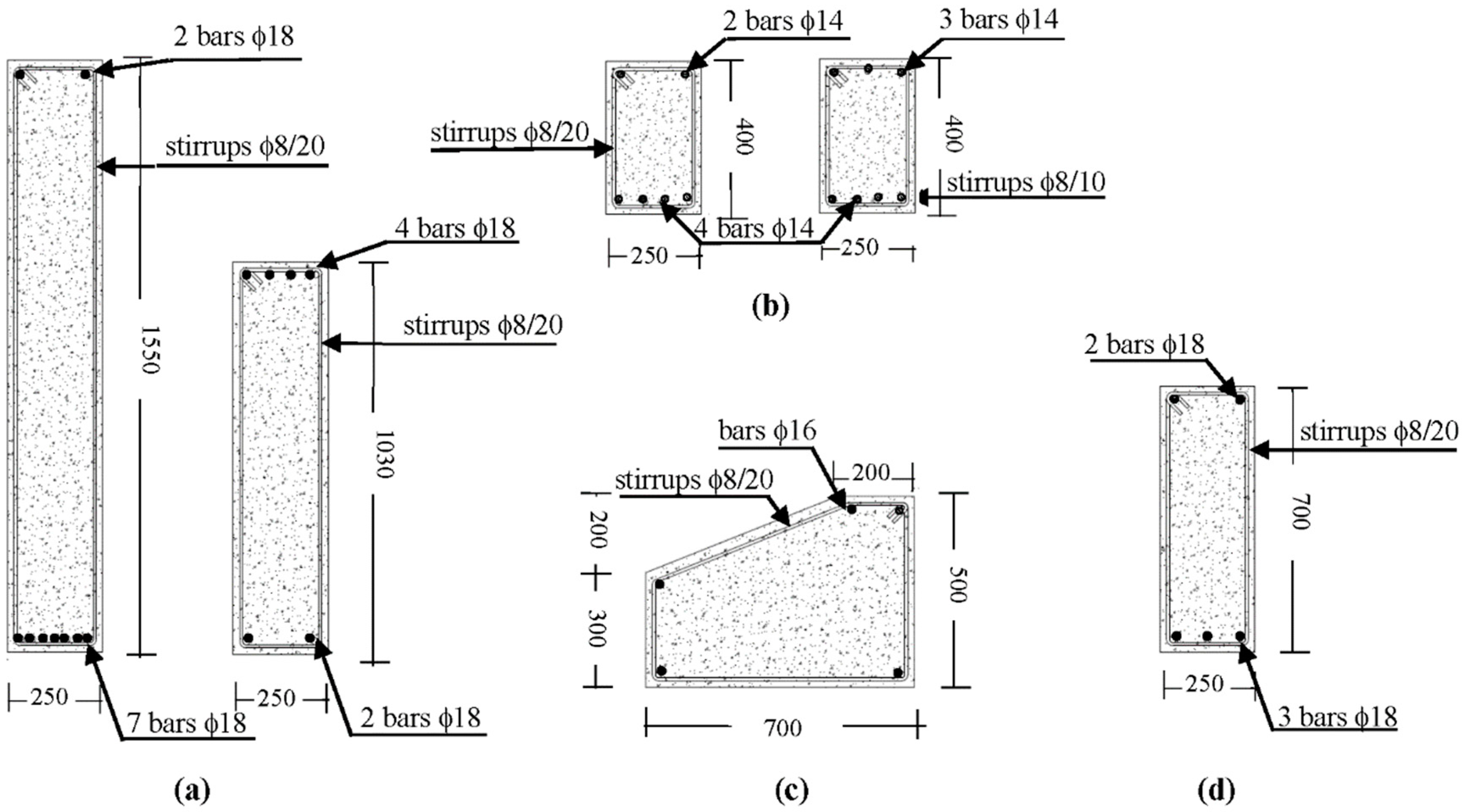
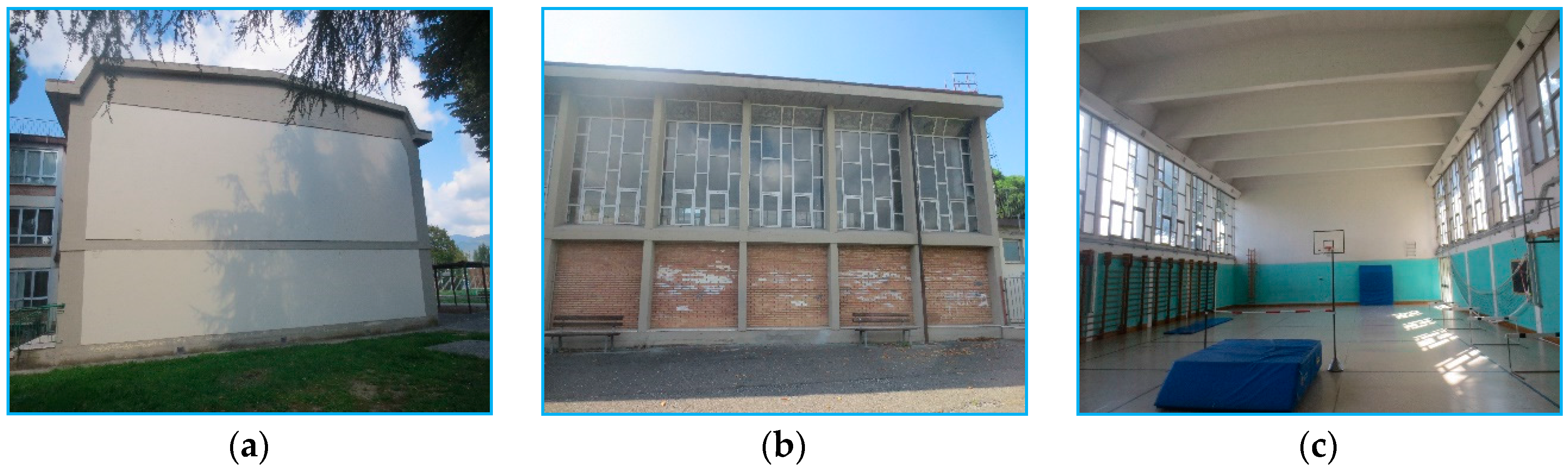
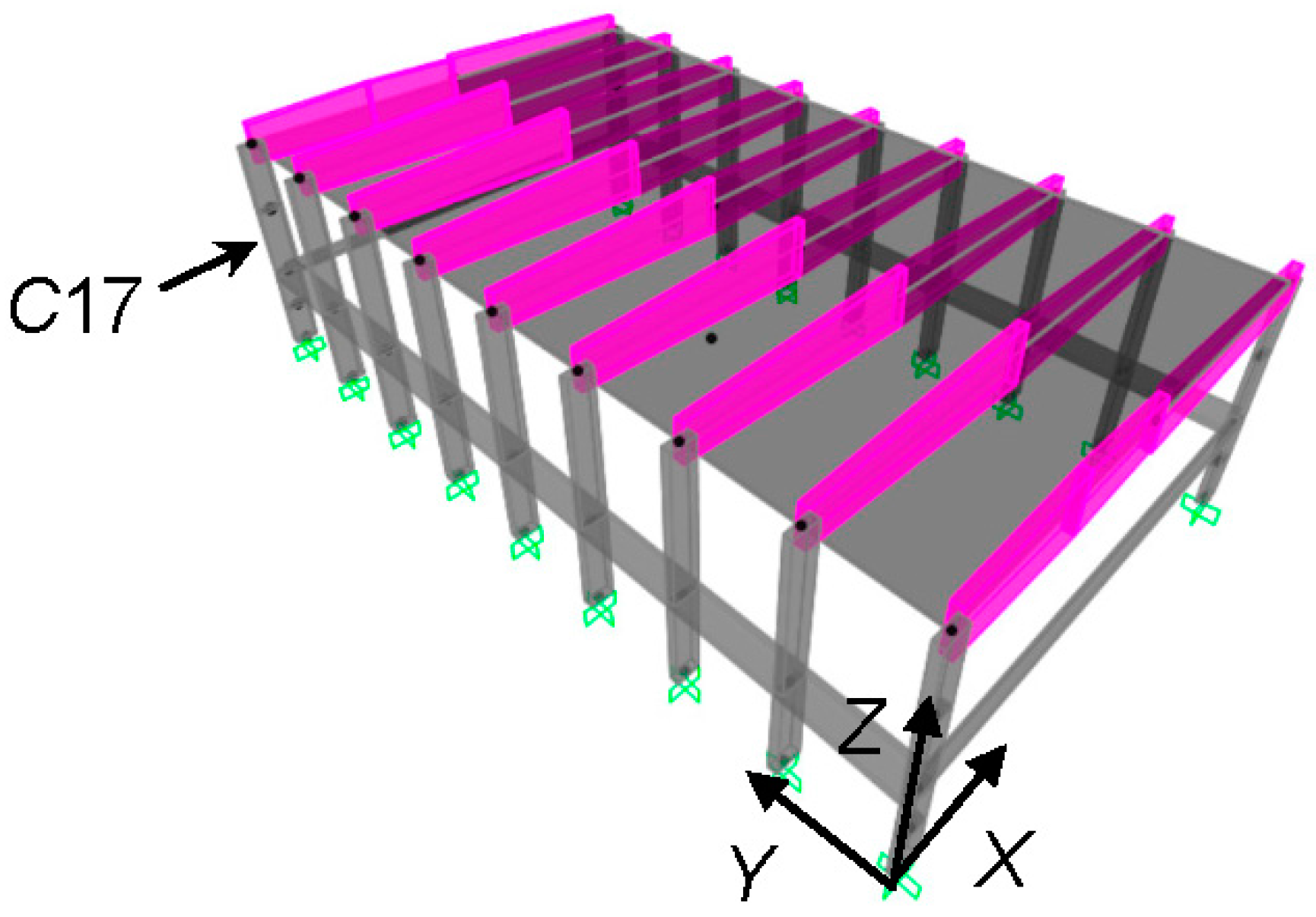
3. Geometrical and Structural Characteristics of the Case-Study Building

The case study examined for a first demonstrative application of the design criterion is the gym in a school in Florence, built in 1971, two external views and an internal view of which are displayed in Figure 3. Figure 4 and Figure 5 show the structural plan and the transversal cross section, respectively. The reference Cartesian coordinate system assumed in the analyses is indicated in Figure 4 and Figure 5, too. As highlighted in Figure 4, the plan is rectangular, with sides of 14.4 m in the transversal direction, parallel to X, and 24.25 m in the longitudinal direction, parallel to Y. The height of the roof top is equal to 9.17 m, whereas the height of the façades, measured on top of the end section of the roof beams, is equal to 8.67 m. The structure is constituted by nine identical RC frames of two columns each, numbered C1–C2 through C17–C18 in Figure 4, placed at a mutual distance of 3 m. The cross sections of the beams and columns and relevant reinforcement details, redrawn from the original structural design drawings, are illustrated in Figure 6.
The columns have a mutual rectangular section with sides of 700 mm along X and 250 mm along Y. The roof beams have a rectangular section with a base of 250 mm and a height varying from 1030 mm, at the ends, to 1540 mm, at half-span. In the longitudinal direction, the columns are connected on top by a rectangular beam, named TB in Figure 5, with dimensions of 250 mm × 400 mm; at a height of 3.17 m, by an intermediate beam, named IB, having a polygonal section with a base of 700 mm and maximum lateral side of 500 mm; and at the base, by a rectangular beam constituting the lateral edge beam of the ground floor, named LEB, with dimensions of 200 mm × 700 mm. The IB beam, which supports the curtain wall-type glazed portions of the façades, subdivides all columns in two levels along the height. The structure of the roof floor is 160 mm thick and made of 120 mm-high and 100 mm-wide partly prefabricated RC joists, parallel to Y and placed at a mutual distance of 400 mm, clay lug bricks, and a 40 mm-thick upper RC slab. The ground floor only differs for the height of the joists, equal to 160 mm, which determines a total thickness of 200 mm. The foundation consists of a 400 mm-thick continuous slab, with 1400 mm-high (slab thickness included) and 250 mm-wide transversal rib beams, which connect the column base sections in X direction and support the ground floor.
A selective investigation campaign was carried out on materials and structural members, including on-site Son-Reb, pacometric and Vickers-type micro-durometer analyses, and laboratory tests on concrete and steel bar samples. On the basis of the prescriptions of Italian Standards [47,49], as well as of professional protocols [50,51], the tests met the basic knowledge level (named LC1 in [49]) for the structural assessment analysis of public buildings in Italy. The corresponding value of the confidence factor, i.e., the additional knowledge level-related safety coefficient to be introduced in stress state checks, is equal to 1.35. The following main properties resulted from the characterization tests: mean cubic compressive strength of concrete equal to 19.6 N/mm2; yield stress and limit stress of steel equal to 417 MPa and 594 MPa, respectively. The total seismic weight of the building is equal to 2960 kN.

4. Verification Analysis in Current Conditions (Step 1 of the Design Procedure)

The verification enquiry in current conditions, constituting Step 1 of the design procedure, is articulated in a modal analysis to calculate the vibration periods and associated modal masses, and in a time-history analysis to assess the seismic performance in terms of stress states and displacements.

4.1. Modal Analysis

The finite element model of the structure, a perspective view of which is displayed in Figure 7, was generated by the SAP2000NL calculus program [52] using frame type elements for all structural members. The modal analysis carried out by the model shows two first horizontal translational modes along X and Y, with vibration periods of 0.89 s (Y) and 0.35 s (X), respectively, and effective modal mass (EMM) equal to 79% along Y and 88.1% along X. The fourth and fifth mode are translational along X and Y too, with periods of 0.26 s (Y) and 0.11 s (X), and EMM equal to 20.9% (Y) and 11.8% (X), which provide summed modal masses with the corresponding first mode-related EMMs nearly equal to 100%, along both axes. The third and sixth mode are purely rotational around the vertical axis Z, with periods of 0.34 s and 0.04 s, and EMM equal to 84.4% and 12.4%, giving a summed modal mass of 96.8%.
The modal parameters quantitatively confirm a notably different translational behaviour of the structure along the two directions in plan, as a consequence of the markedly different sides of the columns along X and Y and the much higher flexural stiffness of the roof beams in comparison to the longitudinal beams.

4.2. Time-History Verification and Performance Assessment Analysis

The performance evaluation enquiry was carried out for the four reference seismic levels fixed in the Italian Standards [47], that is, Frequent Design Earthquake (FDE, with 81% probability of being exceeded over the reference time period VR); Serviceability Design Earthquake (SDE, with 50%/VR probability); Basic Design Earthquake (BDE, with 10%/VR probability); and Maximum Considered Earthquake (MCE, with 5%/VR probability). The VR period is fixed at 75 years, which is obtained by multiplying the nominal structural life VN of 50 years by a coefficient of use Cu equal to 1.5, imposed to structures whose seismic resistance is of importance in view of the consequences associated with their possible collapse, like the case-study school gym building. By referring to topographic category T1 (flat surface) and B-type soil, the resulting peak ground accelerations for the four seismic levels referred to the city of Florence are as follows: 0.065 g (FDE), 0.078 g (SDE), 0.181 g (BDE), and 0.227 g (MCE). The relevant pseudo-acceleration elastic response spectra at linear viscous damping ratio ξ = 5% are plotted in Figure 8.
Time-history analyses were developed by assuming artificial ground motions as inputs, generated in families of seven by the SIMQKE-II software [53] from the spectra above. As required by the Italian Standards [47], as well as by several other international seismic Codes and Regulations [36,46], in each time-history analysis the accelerograms were assumed in groups of two simultaneous horizontal components, with the first one selected from the first generated family of seven motions, and the second one selected from the second family.
The results of the analyses carried out at the FDE and the SDE are evaluated in terms of interlevel drift ratio (i.e., the ratio of the interlevel drift to the interlevel height of the columns) ILDr, which is equivalent to the interstorey drift ratio in the presence of a system of continuous intermediate beams, although without a floor. The maximum ILDr values induced by the most severe among the seven groups of input motions, ILDr,max, are as follows: 0.07% (FDE), 0.09% (SDE) in X, and 0.06% (FDE), 0.07% (SDE) in Y, on the first level; 0.13% (FDE), 0.16% (SDE) in X, and 0.53% (FDE), 0.64% (SDE) in Y, on the second level. The drift ratios in X are far below the 0.33% limitation adopted by [47] at the Operational (OP) performance level for frame structures interacting with drift-sensitive non-structural elements, like the masonry infills on the first level and the curtain wall-type windows on the second level, for the main façades of the building, and the infills situated on both levels, for the side façades. The ILDr,max values obtained on the second level in Y are 1.6 times (FDE) and about twice (SDE) the OP-related limit, and also greater than the drift threshold adopted by [47] for the Immediate Occupancy (IO) performance level, equal to 0.5%.
The ILDr,max values computed for the second level in Y are equal to 1.36% at the BDE, and 1.69% at the MCE, assessing moderate (BDE) to high (MCE) potential plastic demands on the columns—should an inelastic finite element analysis be carried out—and severe (BDE) to very severe (MCE) damage of infills and curtain-wall windows. Consequently, the performance level attained in terms of displacement response is Life Safety (LS), both for the BDE and the MCE. At the same time, ILDr,max is no greater than 0.18% (BDE) and 0.22% (MCE) on the first level in Y, i.e., only 13% of the second level values. This identifies a cantilever-like response of the structure along Y, with structural and non-structural damage located on the second level. As discussed in the following Sections, this suggests incorporating the dissipaters on the upper level only, in order to adequately exploit their damping capacity and limit the cost of the retrofit intervention. In X direction, ILDr,max is equal to 0.2% (BDE), 0.25% (MCE) on the first level, and 0.36% (BDE), 0.45% (MCE) on the second level. The interlevel drift profile depicts a frame-like layout along this axis, which approaches a shear-type shape on the second level, as a consequence of the high flexural stiffness of the roof beams in the XZ vertical plan (which determines nearly a sliding-clamped constraint condition on the top section of the columns).
The BDE- and MCE-related response was assessed also in terms of stress levels. The shear-related checks are met in both directions and for both levels, up to the MCE. On the other hand, the combined axial-force and biaxial-bending-moment stress state checks are met only for the internal columns (C3 through C16, according to the numbering in Figure 4) on the first level at the BDE. The response of the corner columns (C1, C2, C17 and C18) at this level, as well as of all columns on the second level is unsafe starting from the BDE. By way of example, the MX,cMY,c biaxial moment interaction curves (being MX,c, MY,c the bending moments around the X and Y axes) graphed by jointly plotting the two bending moment response histories obtained from the most demanding among the seven groups of MCE-scaled accelerograms, are plotted in Figure 9 for a corner column, namely C17. The boundary of the MX,cMY,c elastic interaction domain—which is a function of the time-history variation of the axial force in the columns—is also traced out in the two graphs for the value of the axial force conventionally referred to the basic combination of gravity loads, i.e., Nc = 104 kN.
The response curves relevant to the first level highlight maximum MX,cMY,c combined values slightly exceeding the safe domain boundary at the BDE, and 1.77 times greater than the corresponding values situated on the boundary, with prevailing contribution of MY,c, at the MCE. The curves traced out for the second level show more marked unsafe conditions at the BDE, as compared to the first-level ones, and exceed the boundary by a factor equal to 2.07 at the MCE, but with inverted role of the moments (i.e., with prevailing contribution of MX,c for the second level).

5. Dissipative Bracing Retrofit Solution

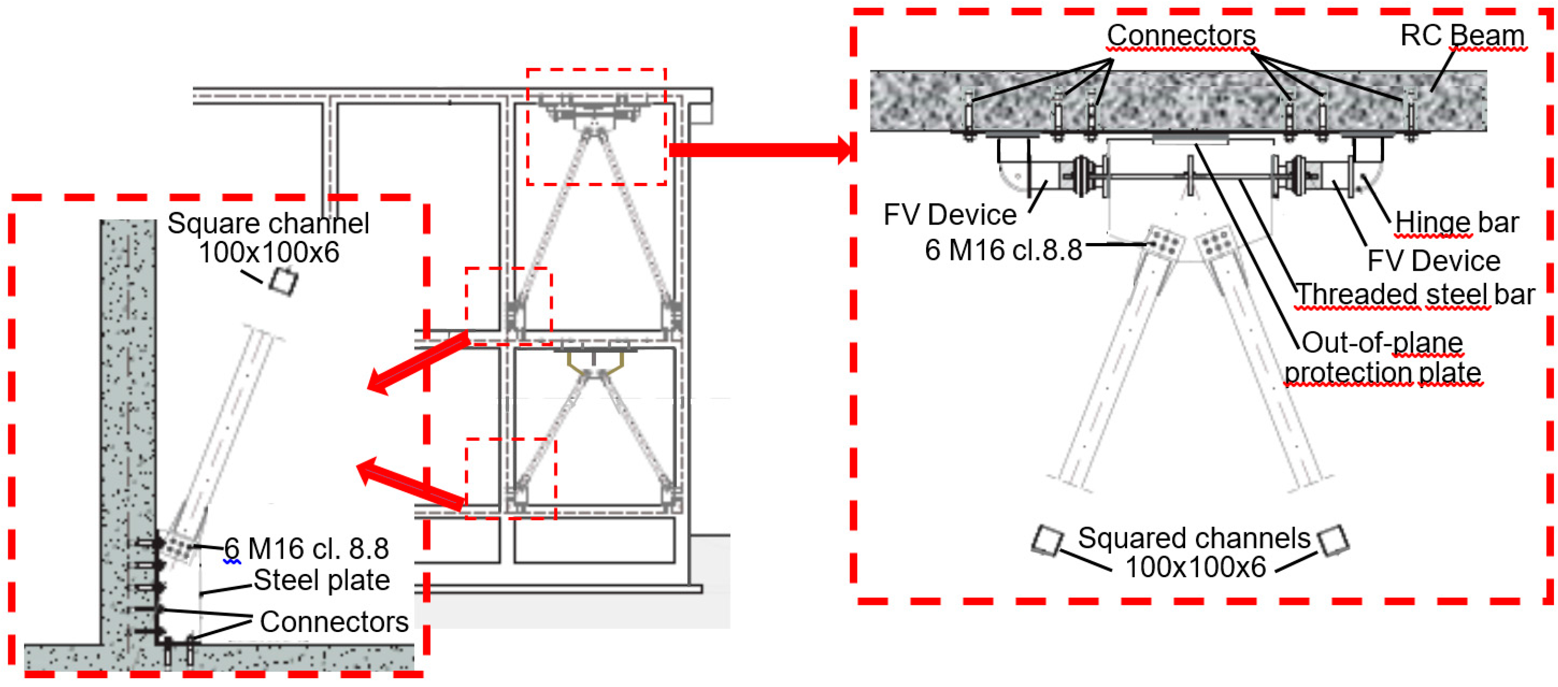
5.1. Characteristics of the Protective System

Fluid viscous devices are among the most widely used types of rate-dependent passive energy dampers installed in dissipative bracing technologies worldwide. This is owed to their high damping capacities, stable mechanical properties over time, simple installation procedures, limited architectural and visual impact, competitive costs and, in the case of pressurized elements, inherent self-centering qualities [54,55,56,57].
Within this class, a special type of pressurized FV devices has been studied for several years by the author and co-authors, focusing attention on their mechanical characterization, the implementation of analytical and numerical models to simulate their dynamic response, the formulation of sizing and design criteria, and the application to several different protective technologies and structural typologies. Concerning their analytical modelling, the time-dependent FD damping and Fne non-linear elastic reaction forces corresponding to the damper and spring functions are effectively simulated by the following expressions [54,56]:
F D ( t ) = c s g n [ x ˙ ( t ) ] | x ˙ ( t ) | γ
F n e ( t ) = k 2 x ( t ) + ( k 1 k 2 ) x ( t ) [ 1 + | k 1 x ( t ) F 0 | 5 ] 1 / 5
where t = time variable; c = damping coefficient; sgn(·) = signum function; x ˙ ( t ) = device velocity; |·| = absolute value; γ = fractional exponent, ranging from 0.1 to 0.2; F0 = static pre-load force; k1, k2 = stiffness of the response branches situated below and beyond F0; and x(t) = device displacement. For the development of the numerical analyses, the finite element model of a FV spring–damper is obtained by combining in parallel a non-linear dashpot and a non-linear spring with reaction forces given by expressions (22) and (23), respectively. Both types of elements are currently incorporated in commercial structural analysis programs, such as the SAP2000NL code used in this study.
The installation layout of the spring–dampers and the dissipative bracing system within the frame skeleton is illustrated by the drawings in Figure 10, referred to the case-study building and corresponding to the basic configuration devised for RC buildings.
Therein, a pair of interfaced devices is placed in parallel with the connecting beam axis at the tip of each couple of supporting braces. A half-stroke initial position is imposed on site to the pistons of both spring–dampers, so as to obtain symmetrical tension–compression response cycles—like the one traced out in the scheme of Figure 2—starting from a compressive-only response of the single devices. This position is obtained during the assembly operations by acting on a pair of threaded steel bars crossing the interfacing plate of each device and connected to two other bored plates, screwed into the external casing of the spring–dampers.

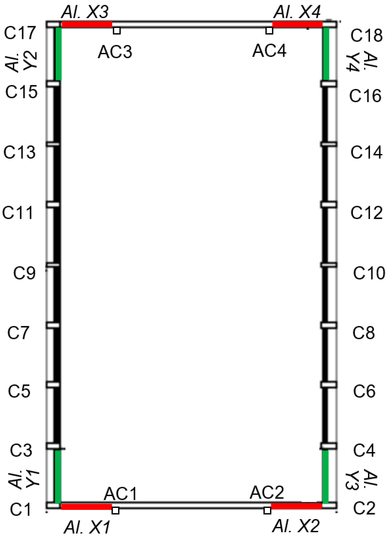
5.2. Application of the Design Method to the Case-Study Building

As shown in the building plan in Figure 11, the dissipative braces are placed in four alignments parallel to X (named Al. X1 through Al. X4) and four alignments parallel to Y (Al. Y1Al. Y4). The latter are constituted by pairs of adjacent columns (C1–C3—Al. Y1, C15–C17—Al. Y2, C2–C4—Al. Y3, C16–C18—Al. Y4). Concerning the X-parallel alignments, because the beam span is about 11 m long, four additional RC columns with mutual section 250 mm × 250 mm, named AC1 through AC4 in Figure 11, are built at a distance of 3 m from the corner columns prior to mounting the bracing members.
Based on the results of the assessment analysis reported in Section 4, the dampers are incorporated on the second level only, since the first level drifts, computed in current conditions, can produce only a marginal activation even of the smallest FV devices in standard manufacturing. Consequently, traditional non-dissipative braces are installed on the first level in the same four plus four vertical alignments, so as to provide the necessary structural continuity with the dissipative bracing system placed on the second level, as illustrated in the elevation view of Figure 10, but without adding any further supplemental damping contribution. The application of steps 2 through 4 of the design procedure is summarized below for X and Y directions.

5.2.1. X Direction—Lack of Bending Moment Strength in the Columns

Step 2. The verification analysis in current conditions highlights that the most critical response parameters in X direction are the bending moments around Y (i.e., MY) in the first-level columns, with the highest unsafe conditions checked in the four corner columns. By referring to the nomenclature in Section 2.1, the maximum moment M Y , c a corresponding to the peak response point in Figure 9c and associated with the concurrent axial force Nc = 104 kN mentioned above, is equal to 398.7 kNm. The elastic limit moment M Y , c e of the corner columns around the Y axis is equal to 224.8 kNm. Thus, the stress reduction factor α s = α M Y of the critical members in X direction results as follows:
α s = α M Y = M Y , c a M Y , c e = 1.77
Passing from the member to the frame-structure level (equivalent to the frame structure storey for this case-study building), since all columns have the same cross section, αF ratio coincides with αMY:
α F = α M Y = 1.77
Step 3. On the basis of this value, the equivalent viscous damping ratio of the set of spring–dampers to be installed on the second level is evaluated by means of relation (14), obtaining:
ξ e q , α F = 2 π ( α F 1 ) α F = 0.277
Step 4. The ED energy dissipation capacity of the spring–dampers is calculated by expression (18). The elastic limit values of the level shear Fe (i.e., the sum of the elastic limit shear forces of the columns) and the first interlevel drift ILDe (replacing IDe in this case) computed in X direction, named Fe,X and ILDe,1L,X, are equal to 969 kN and 22 mm, respectively. Introducing these values, as well as αF and ξ e q , α F values given by (25) and (26), in (18), the following ED estimate is derived:
E D , α F = 2 π α F F e , X ξ e q , α F I D e , 1 L , X = 65.6   kJ
Dividing ED by the number of spring–dampers placed in X, the minimum energy dissipation capacity ED,X,d to be assigned to each of the eight devices in order to reach the target performance at the MCE results as follows: ED,X,d = 8.2 kJ. The spring–damper type with the nearest nominal energy dissipation capacity, En, to ED,X,d has the following mechanical properties, drawn from the manufacturer’s catalogue [48]: En = 9 kJ; stroke smax = ±30 mm; damping coefficient c = 9.9 kN(s/mm)γ, with γ = 0.15; F0 = 17 kN; and k2 = 1.74 kN/mm.

5.2.2. Y Direction—Lack of Bending Moment Strength in the Columns and Excessive Inter Level Drift

Step 2. The critical response parameters in Y direction are represented by the bending moments around X (MX) in the second-level columns, with the highest unsafe conditions checked in the four corner columns too, and the second interlevel drifts. The maximum moment M X , c a , corresponding in this case to the peak response point in Figure 9d, is equal to 174.2 kNm, whereas the elastic limit moment M X , c e is equal to 84.2 kNm. Therefore, the stress reduction factor α s = α M X of the critical members in Y direction is:
α s = α M X = M X , c a M X , c e = 2.07
and thus:
α F = α M X = 2.07
The deformation-related reduction factor αd given by (19) is calculated for the ILDmax (replacing IDmax) and ILDe (replacing IDe) values computed on the second level in Y direction, named ILDmax,2L,Y, ILDe,2L,Y in the following. ILDmax,2L,Y—corresponding to the ILDr,max value of 1.69% mentioned in Section 4.2—is equal to 72.7 mm, and ILDe,2L,Y to 36.8 mm, yielding:
α d = I L D m a x , 2 L , Y I L D e , 2 L , Y = 1.98
Step 3. The equivalent viscous damping ratio is calculated in this case by referring both to αF and to αd, using expressions (14) and (20), respectively:
ξ e q , α F = 2 π ( α F 1 ) α F = 0.33
ξ e q , α d = 2 π ( α d 1 ) = 0.624
Step 4. Named Fe,Y the elastic limit level shear in Y direction, by applying the ED energy dissipation capacity expressions (18) and (21), the following ED estimates are obtained:
E D , α F = 2 π α F F e , Y ξ e q , α F I L D e , 2 L , Y = 100.8   kJ
E D , α d = 2 π F e , Y ξ e q , α d I L D e , 2 L , Y = 92.1   kJ
where Fe,Y = 638 kN.
By comparing ξ e q , α F with ξ e q , α d , and E D , α F with E D , α d , it can be observed that the relevant ratios are rather different. Indeed: ξ e q , α d / ξ e q , α F = 1.89, E D , α F / E D , α d = 1.1. This is due to the fact that, consistently with the general ξeq expression (5), the damping coefficient depends on Ee, and thus on the elastic properties of the device, which are a function of the maximum displacement and force reached in the time-history response, in addition to the hysteretic response. On the other hand, the dissipated energy ED is only determined by the area covered by the response cycles, which identifies it as a more stable and reliable parameter for the design of the FV devices. ξeq is only a useful synthetic measure of their limit damping capacity.
The design process is completed by referring to the largest of the energy values, E D , α F , E D , α d , i.e., E D , α F = 100.8 kJ. Similarly to the X direction, the minimum energy dissipation capacity of each of the eight devices placed in Y, ED,Y,d, in order to achieve the target performance at the MCE, is obtained by dividing E D , α F by the number of spring–dampers: ED,Y,d = 12.6 kJ. The device with the nearest nominal energy dissipation capacity to ED,Y,d has the following mechanical properties: En = 14 kJ; stroke smax = ±40 mm; damping coefficient c = 14.16 kN(s/mm)γ, with γ = 0.15; F0 = 28 kN; and k2 = 2.1 kN/mm.

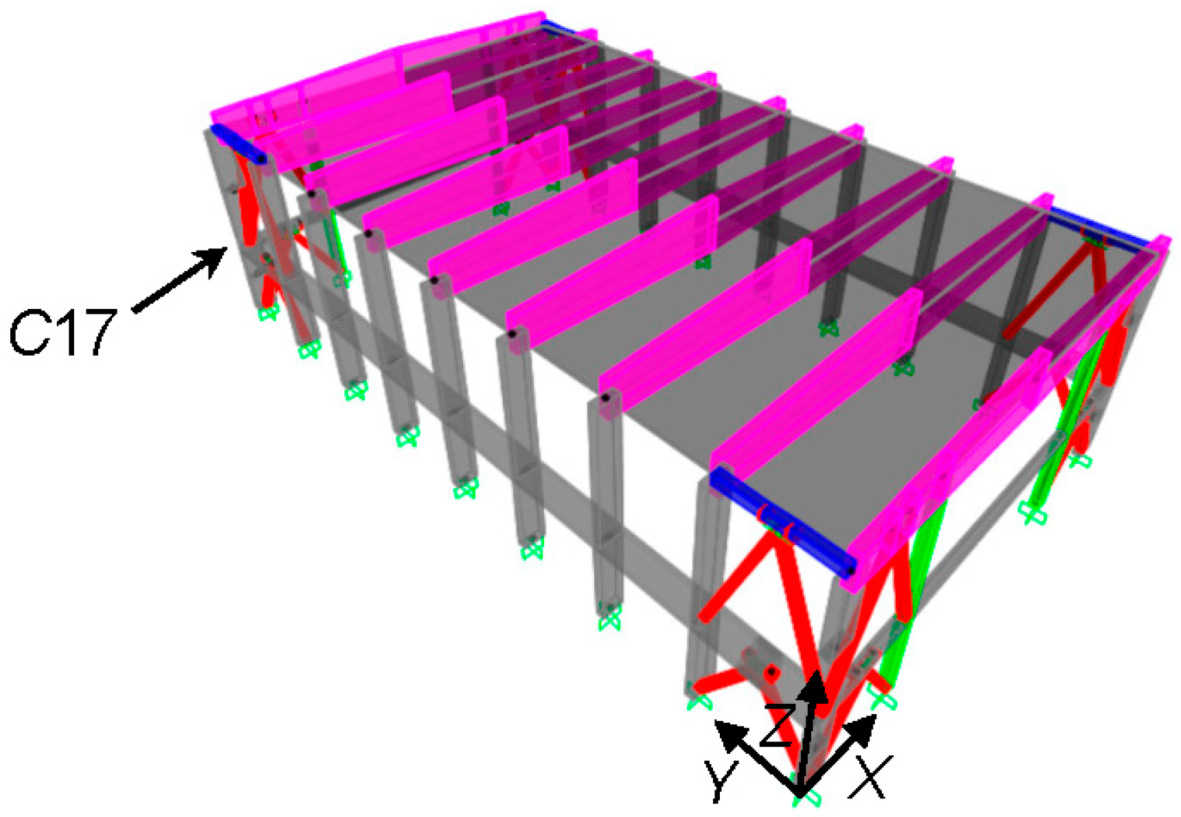
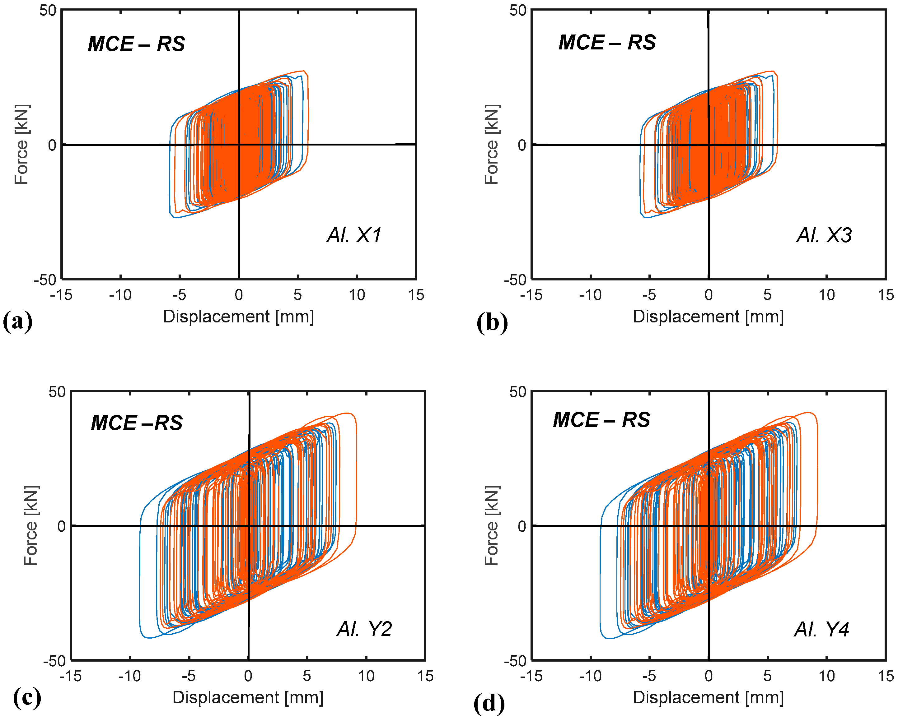
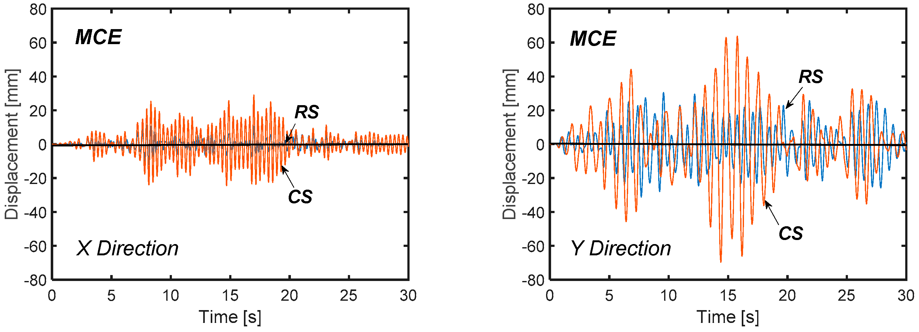
5.3. Numerical Verification of the Retrofit Solution

A perspective view of the model including the dissipative bracing system is displayed in Figure 12. The modal analysis carried out in retrofitted conditions confirms the sequence of modes computed in current state, with differences on periods and EMMs lower than 10%, as a consequence of the small stiffening effect of this technology. The periods and EMMs of the two first horizontal translational modes along X and Y pass to 0.83 s (Y) and 0.32 s (X), and to 79.5% (Y) and 88.1% (X); the periods and EMMs of the fourth and fifth mode, translational along X and Y, to 0.25 s (Y) and 0.105 s (X), and to 20.3% (Y) and 11.7% (X). The relevant summed modal masses are nearly equal to 100% along both axes, in this case too. The third and sixth mode, rotational around Z, have periods of 0.33 s and 0.037 s, and EMM equal to 84.9% and 13.8%, giving a summed modal mass of 98.7%.
The results of the time-history verification analyses in rehabilitated configuration are synthesized in Figure 13, Figure 14, Figure 15 and Figure 16, all referred to the response induced by the most demanding of the seven groups of input ground motions scaled at the MCE level. The MXcMYc interaction curves of the first and second level base sections of column C17, plotted in Figure 9c,d above for the original structure, are duplicated in Figure 13 in retrofitted conditions. The two graphs show that the dissipative action of the protective system allows confining the interaction curves within the biaxial moment safe domain, reducing the maximum MYc (Figure 13a) and MXc (Figure 13b) moments nearly by the targeted αMY and αMX factors of 1.77 and 2.07, as given by (24) and (29).
The response cycles of the pairs of spring–dampers situated along the opposite vertical alignments Al. X1, Al. X3, and Al. Y2, Al. Y4 are visualized in Figure 14. The cycles exhibit peak displacements equal to 6.3 mm (Al. X1, Al. X3) and 8.8 mm (Al. Y2, Al. Y4), far below the available stroke limits of ±30 mm (in X) and ±40 mm (in Y) mentioned above. Furthermore, the response of the devices placed in Al. X1 and Al. X3 are nearly coincident, and the same occurs for the devices situated in Al. Y2 and Al. Y4, highlighting that torsion effects in plan are virtually null.
The energy time-histories graphed in Figure 15, where EI and ED denote the total input and dissipated energies, and EI,X, ED,X, EI,Y, ED,Y the relevant portions in X and Y, show ED,X, ED,Y values of 66.9 kJ and 101.9 kJ, which differ only by 2% and 1% from the corresponding E D , α F estimates (27) and (33), respectively.
Furthermore, practically identical values of the ED/EI ratio are found in X and Y, namely: ED,X/EI,X = 0.855; ED,Y/EI,Y = 0.85, identifying a well-balanced energy dissipation demand in the two directions.
The roof top displacement time-histories illustrated in Figure 16 show a reduction factor on the peak values equal to about 2.3 (X) and 2.2 (Y) when passing from current (CS) to retrofitted (RS) conditions. In the most deformable direction Y, this corresponds to a drop of the second-level drift from 72.7 mm to 33.8 mm, i.e., below the corresponding elastic limit value ILDe,2L,Y = 36.8 mm, as targeted in the design.

6. Conclusions

The energy-based design criterion formulated in this study for the seismic retrofit of frame buildings by means of dissipative bracing technologies does not require any preliminary evaluation of the input energy demand on the original structure. At the same time, the most critical response parameters in current conditions—the reduction of which within the boundary of relevant safe domains (in case of lack of strength), or below the limits preventing damage to structural and non-structural elements (in case of excessive lateral displacements)—are evaluated by a conventional elastic finite element analysis. Both aspects of the initializing step of the sizing procedure allow simplifying the design of supplemental damping-based retrofit solutions, which can be useful especially for professional engineers not familiar with seismic energy computation and the development of non-linear time-history analyses.
The criterion was detailed here for relatively stiff structures, i.e., with a fundamental translational vibration period in original conditions below 0.8 s, where the retrofit design objectives can be met by an added damping, with a marginal role of supplemental stiffness. This prompted to select the bracing systems that incorporate FV spring–dampers as protective devices, because they provide a moderate contribution to the lateral stiffness of the retrofitted structures. However, the procedure can be extended with little modifications to dissipative bracing technologies that significantly increase the translational stiffness too, like the systems including metallic dampers, which will be the subject of a further step of the study.
The demonstrative application to the considered case-study structure allowed checking the quick sizing characteristics of the design criterion, even when stress state-related and drift-related deficiencies are both found in the original structure (as occurs in Y direction of the gym building). Furthermore, the values of the equivalent damping coefficient ratio calculated as a function of the reduction factors αF, αd relevant to stress states and drifts, using formulas (14) and (20), respectively, resulted to be notably different. On the other hand, a slight difference was found between the corresponding energy dissipation measures, E D , α F and E D , α d . This identified ED as a more stable and reliable design parameter, as compared to ξeq, consistently with the fact that ED is only determined by the area covered by the response cycles of the dissipaters. This was also confirmed by the fact that the ED values in X and Y computed from the time-history verification analysis were very similar to the E D , α F estimates.
As targeted in the retrofit design, the incorporation of the protective system in the gym building allows reaching an elastic and safe response of all members, as well as constraining the interlevel drifts below the Immediate Occupancy drift limit, up to the MCE, starting from a rather poor performance in original conditions.

Acknowledgments

The study reported in this paper was sponsored by the Italian Department of Civil Protection within the ReLUIS-DPC Project 2014/2018, Research Line 6: Isolation and Dissipation. The author gratefully acknowledges this financial support.

Conflicts of Interest

The author declares no conflict of interest.

References

  1. Fenz, D.M.; Constantinou, M.C. Spherical sliding isolation bearings with adaptive behavior: Theory. Earthq. Eng. Struct. Dyn. 2008, 37, 163–183. [Google Scholar] [CrossRef]
  2. Fenz, D.M.; Constantinou, M.C. Spherical sliding isolation bearings with adaptive behavior: Experimental verification. Earthq. Eng. Struct. Dyn. 2008, 37, 185–205. [Google Scholar] [CrossRef]
  3. Quaglini, V.; Gandelli, E.; Dubini, P. Experimental investigation of the re-centring capability of curved surface sliders. Struct. Control Health Monit. 2017, 24. [Google Scholar] [CrossRef]
  4. Sorace, S.; Terenzi, G. Seismic performance assessment and base isolated floor-protection of statues exhibited in museum halls. Bull. Earthq. Eng. 2015, 13, 1873–1892. [Google Scholar] [CrossRef]
  5. Butterworth, J.W. Seismic response of a non-concentric rolling isolator system. Adv. Struct. Eng. 2006, 9, 39–54. [Google Scholar] [CrossRef]
  6. Guerreiro, L.; Azevedo, J.; Muhr, A.H. Seismic tests and numerical modeling of a rolling-ball isolation system. J. Earthq. Eng. 2007, 11, 49–66. [Google Scholar] [CrossRef]
  7. Foti, D.; Catalan Goni, A.; Vacca, S. On the dynamic response of rolling base isolation systems. Struct. Control Health Monit. 2013, 20, 639–648. [Google Scholar] [CrossRef]
  8. Mahmoudi, M.; Abdi, M.G. Evaluating response modification factors of TADAS frames. J. Constr. Steel Res. 2012, 71, 162–170. [Google Scholar] [CrossRef]
  9. Saeedi, F.; Shabakhty, N.; Mousavi, S.R. Seismic assessment of steel frames with triangular-plate added damping and stiffness devices. J. Constr. Steel Res. 2016, 125, 15–25. [Google Scholar] [CrossRef]
  10. Foti, D.; Diaferio, M.; Nobile, R. Optimal design of a new seismic passive protection device made in aluminium and steel. Int. J. Struct. Eng. Mech. 2010, 35, 119–122. [Google Scholar] [CrossRef]
  11. Foti, D.; Nobile, R. Optimum design of a new hysteretic dissipater. In Design Optimization of Active and Passive Structural Control Systems; Chapter 12; Lagaros, N.D., Plevris, V., Mitropoulou, C.C., Eds.; IGC Global: Hershey, PA, USA, 2012; pp. 274–299. [Google Scholar] [CrossRef]
  12. Sorace, S.; Terenzi, G.; Mori, C. Passive energy dissipation-based retrofit strategies for R/C frame water storage tanks. Eng. Struct. 2016, 106, 385–398. [Google Scholar] [CrossRef]
  13. Kang, T.H.-K.; Martin, R.D.; Park, H.-G.; Wilkerson, R.; Youssef, N. Tall building with steel plate shear walls subject to load reversal. Struct. Des. Tall Spec. Build. 2013, 22, 500–520. [Google Scholar] [CrossRef]
  14. Jain, S.; Rai, D.C.; Sahoo, D.R. Postyield cyclic buckling criteria for aluminum shear panels. J. Appl. Mech. Trans. ASME 2008, 75, 210151–210158. [Google Scholar] [CrossRef]
  15. Hamed, A.A.; Mofid, M. On the equivalent simple models of braced steel shear panels. Proc. Inst. Civil Eng. Struct. Build. 2015, 168, 570–577. [Google Scholar] [CrossRef]
  16. Hamed, A.A.; Mofid, M. On the experimental and numerical study of braced steel shear panels. Struct. Des. Tall Spec. Build. 2015, 24, 853–872. [Google Scholar] [CrossRef]
  17. De Matteis, G.; Brando, G.; Panico, S.; Mazzolani, F.M. Bracing type pure aluminium stiffened shear panels: An experimental study. Adv. Steel Constr. 2009, 5, 106–119. [Google Scholar]
  18. Zhang, C.; Zhu, J.; Wu, M.; Yu, J.; Zhao, J. The lightweight design of a seismic low-yield-strength steel shear panel damper. Materials 2016, 9, 424. [Google Scholar] [CrossRef] [PubMed]
  19. Vian, D.; Bruneau, M.; Purba, R. Special perforated steel plate shear walls with reduced beam section anchor beams. II: Analysis and design recommendations. J. Struct. Eng. 2009, 135, 221–228. [Google Scholar] [CrossRef]
  20. De Matteis, G.; Sarracco, G.; Brando, G. Experimental tests and optimization rules for steel perforated shear panels. J. Constr. Steel Res. 2016, 123, 41–52. [Google Scholar] [CrossRef]
  21. Valizadeh, H.; Sheidaii, M.; Showkati, H. Experimental investigation on cyclic behavior of perforated steel plate shear walls. J. Constr. Steel Res. 2012, 70, 308–316. [Google Scholar] [CrossRef]
  22. Chan, R.W.K.; Albermani, F.; Kitipornchai, S. Experimental study of perforated yielding shear panel device for passive energy dissipation. J. Constr. Steel Res. 2013, 91, 14–25. [Google Scholar] [CrossRef]
  23. Egorova, N.; Eatherton, M.R.; Maurya, A. Experimental study of ring-shaped steel plate shear walls. J. Constr. Steel Res. 2014, 103, 179–189. [Google Scholar] [CrossRef]
  24. Qu, B.; Liu, X.; Hou, H.; Qiu, C.; Hu, D. Testing of buckling-restrained braces with replaceable steel angle fuses. J. Struct. Eng. 2018, 144. [Google Scholar] [CrossRef]
  25. Lin, P.-C.; Tsai, K.-C.; Chang, C.-A.; Hsiao, Y.-Y.; Wu, A.-C. Seismic design and testing of buckling-restrained braces with a thin profile. Earthq. Eng. Struct. Dyn. 2016, 45, 339–358. [Google Scholar] [CrossRef]
  26. Deng, K.; Pan, P.; Li, W.; Xue, Y. Development of a buckling restrained shear panel damper. J. Constr. Steel Res. 2015, 106, 311–321. [Google Scholar] [CrossRef]
  27. Brando, G.; D’Agostino, F.; De Matteis, G. Experimental tests of a new hysteretic damper made of buckling inhibited shear panels. Mater. Struct. 2013, 46, 2121–2133. [Google Scholar] [CrossRef]
  28. Christopoulos, C.; Filiatrault, A. Principles of Passive Supplemental Damping and Seismic Isolation; IUSS Press: Pavia, Italy, 2006; ISBN 88-7358-037-8. [Google Scholar]
  29. Altieri, D.; Tubaldi, E.; Pratelli, E.; Dall’Asta, A. Assessment of optimal design methods of viscous dampers. Procedia Eng. 2017, 199, 1152–1157. [Google Scholar] [CrossRef]
  30. Lavan, O.; Dargush, G.F. Multi-objectve evolutionary seismic design with passive energy dissipation systems. J. Earthq. Eng. 2009, 13, 758–790. [Google Scholar] [CrossRef]
  31. Sorace, S.; Terenzi, G. Seismic protection of frame structures by fluid viscous damped braces. J. Struct. Eng. ASCE 2008, 134, 45–55. [Google Scholar] [CrossRef]
  32. Sorace, S.; Terenzi, G.; Fadi, F. Shaking table and numerical seismic performance evaluation of a fluid viscous-dissipative bracing system. Earthq. Spectra 2012, 28, 1619–1642. [Google Scholar] [CrossRef]
  33. Ramirez, O.M.; Costantinou, M.C.; Whittaker, A.S.; Kircher, C.A.; Chrysostomou, C.Z. Elastic and Inelastic Seismic Response of Buildings with Damping Systems. Earthq. Spectra 2002, 18, 531–547. [Google Scholar] [CrossRef]
  34. Soong, T.T.; Spencer, B.F. Supplemental energy dissipation: State-of-the-art and state-of-the-practice. Eng. Struct. 2002, 24, 243–259. [Google Scholar] [CrossRef]
  35. Whittaker, A.; Costantinou, M.; Ramirez, O.; Johnson, M.; Chrysostomou, C. Equivalent lateral force and modal analysis procedures for the 2000 NEHRP provisions for buildings with damping systems. Earthq. Spectra 2003, 19, 959–980. [Google Scholar] [CrossRef]
  36. ASCE/SEI 41-06. Seismic Rehabilitation of Existing Buildings; American Society of Civil Engineers—Structural Engineering Institute: Reston, VA, USA, 2006. [Google Scholar]
  37. ASCE 7-10. Minimum Design Loads for Buildings and Other Structures; American Society of Civil Engineers: Reston, VA, USA, 2010. [Google Scholar]
  38. Silvestri, S.; Gasparini, G.; Trombetti, T. A five-step procedure for the dimensioning of viscous dampers to be inserted in building structures. J. Earthq. Eng. 2010, 14, 417–447. [Google Scholar] [CrossRef]
  39. Palermo, M.; Muscio, M.; Silvestri, S.; Landi, L.; Trombetti, T. On the dimensioning of viscous dampers for the mitigation of the earthquake-induced effects in moment-resisting frame structures. Bull. Earthq. Eng. 2013, 11, 2429–2446. [Google Scholar] [CrossRef]
  40. Bergami, A.V.; Nuti, C. A design procedure of dissipative braces for seismic upgrading structures. Earthq. Struct. 2013, 4, 85–108. [Google Scholar] [CrossRef]
  41. Mazza, F.; Mazza, M.; Vulcano, A. Displacement-based seismic design of hysteretic damped braces for retrofitting in-elevation irregular r.c. framed structures. Soil Dyn. Earthq. Eng. 2015, 69, 115–124. [Google Scholar] [CrossRef]
  42. Mazza, F. Comparative study of the seismic response of RC framed buildings retrofitted using modern techniques. Earthq. Struct. 2015, 9, 29–48. [Google Scholar] [CrossRef]
  43. Levy, R.; Lavan, O. Fully stressed design of passive controllers in framed structures for seismic loading. Struct. Multidiscip. Optim. 2006, 32, 485–498. [Google Scholar] [CrossRef]
  44. Brando, G.; D’Agostino, F.; De Matteis, G. Seismic performance of MR frames protected by viscous or hysteretic dampers. Struct. Des. Tall Spec. Build. 2015, 24, 653–671. [Google Scholar] [CrossRef]
  45. Pollini, N.; Lavan, O.; Amir, O. Minimum-cost optimization of nonlinear fluid viscous dampers and their supporting members for seismic retrofitting. Earthq. Eng. Struct. Dyn. 2017, 46, 1941–1961. [Google Scholar] [CrossRef]
  46. EN 1998-4. Eurocode 8: Design of structures for earthquake resistance—Part 1: General seismic rules. In Seismic Actions and Rules for Buildings; European Committee for Standardisation: Brussels, Belgium, 2003. [Google Scholar]
  47. Italian Council of Public Works. Technical Standards on Constructions; Italian Council of Public Works: Rome, Italy, 2008. (In Italian) [Google Scholar]
  48. Jarret, S.L. Shock-Control Technologies. 2017. Available online: http://www.introini.info (accessed on 30 December 2017).
  49. Italian Council of Public Works. Commentary on the Technical Standards on Constructions; Italian Council of Public Works: Rome, Italy, 2009. (In Italian) [Google Scholar]
  50. Pieraccini, M.; Parrini, F.; Fratini, M.; Atzeni, C.; Spinelli, P.; Micheloni, M. Static and dynamic testing of bridges through microwave interferometry. NTD E Int. 2007, 40, 208–214. [Google Scholar] [CrossRef]
  51. Allend, D.E. Safety criteria for the evaluation of existing structures. In Proceedings of the IABSE Colloquium—Remaining Structural Capacity, Copenhagen, Denmark, 17–19 March 1993. [Google Scholar]
  52. SAP2000NL. Theoretical and Users’ Manual; Release 18.05; Computers & Structures Inc.: Berkeley, CA, USA, 2017. [Google Scholar]
  53. Vanmarcke, E.H.; Fenton, G.A.; Heredia-Zavoni, E. SIMQKE-II—Conditioned Earthquake Ground Motion Simulator: User’s Manual; Version 2.1; Princeton University: Princeton, NJ, USA, 1999; Available online: http://nisee.berkeley.edu/documents/SW/SIMQKE-II-V2-1.pdf (accessed on 23 November 2017).
  54. Terenzi, G. Effetti Dissipativi Nell’isolamento Sismico. Ph.D. Thesis, University of Florence, Florence, Italy, 1996. (In Italian). [Google Scholar]
  55. Terenzi, G. Dynamics of SDOF systems with nonlinear viscous damping. J. Eng. Mech. ASCE 1999, 125, 956–963. [Google Scholar] [CrossRef]
  56. Sorace, S.; Terenzi, G. Non-linear dynamic modelling and design procedure of FV spring-dampers for base isolation. Eng. Struct. 2001, 23, 1556–1567. [Google Scholar] [CrossRef]
  57. Sorace, S.; Terenzi, G. Motion control-based seismic retrofit solutions for a R/C school building designed with earlier Technical Standards. Bull. Earthq. Eng. 2014, 12, 2723–2744. [Google Scholar] [CrossRef]
Figure 1. Schematic response of the critical structural member (a) and the frame structure storey to which it belongs (b).
Applsci 08 00268 g001
Figure 2. Schematic response cycle of the set of fluid viscous (FV) spring–dampers installed on a storey, and parameters for evaluating ξeq.
Applsci 08 00268 g002
Figure 3. Lateral (a); front (b); and internal (c) views of the building.
Applsci 08 00268 g003
Figure 4. Structural plan of the building (dimensions in millimeters).
Applsci 08 00268 g004
Figure 5. Cross section of the building (dimensions in millimeters).
Applsci 08 00268 g005
Figure 6. Redrawn cross sections of: (a) roof beams–half-span and ends; (b) top longitudinal beams TB—half-span and ends; (c) intermediate longitudinal beams IB; (d) columns (dimensions in millimeters).
Applsci 08 00268 g006
Figure 7. View and reference coordinate system of the finite element model.
Applsci 08 00268 g007
Figure 8. Normative pseudo-acceleration elastic response spectra for Florence.
Applsci 08 00268 g008
Figure 9. Current state (CS). MX,cMY,c biaxial moment interaction curves at the base section of column C17 on the first level (a,c) and second level (b,d) obtained from the most demanding BDE-scaled (a,b) and MCE-scaled (c,d) group of accelerograms.
Applsci 08 00268 g009
Figure 10. Installation details of the dissipative bracing system in the case-study building.
Applsci 08 00268 g010
Figure 11. Positions of the dissipative bracing system alignments in plan.
Applsci 08 00268 g011
Figure 12. View of the finite element model incorporating the dissipative bracing system.
Applsci 08 00268 g012
Figure 13. Retrofitted structure (RS). MX,cMY,c biaxial moment interaction curves at the base section of column C17 on the first level (a) and second level (b) obtained from the most demanding MCE-scaled group of accelerograms.
Applsci 08 00268 g013
Figure 14. Retrofitted structure (RS). Response cycles of the spring–damper pairs installed in Al. X1 (a), Al. X3 (b), Al. Y2 (c) and Al. Y4 (d) vertical alignments obtained from the most demanding MCE-scaled group of accelerograms.
Applsci 08 00268 g014
Figure 15. Retrofitted structure (RS). Energy time-histories obtained from the most demanding MCE-scaled group of accelerograms.
Applsci 08 00268 g015
Figure 16. Rooftop displacement time-histories in X and Y direction obtained from the most demanding MCE-scaled group of accelerograms.
Applsci 08 00268 g016

