1. Introduction
Due to the heavy-duty vehicle traffic and frequency of hot weather, rutting damage of pavement has become increasingly prominent. In recent years, road researchers have explored many approaches to prevent rutting effectively. High-modulus asphalt concrete (HMAC) was first used in France to improve the modulus of pavement, and has gained increasing application in the road industry. In 1980, HMAC was first applied to road reinforcement and maintenance [
1]. After that, with the fuel crisis, HMAC was applied more to both the base and surface layers of new roads. The standard for construction and design of the high modulus asphalt pavement was proposed by the French researchers in 1992. During the 1990s, the French P.R. INDUSTRI Co. developed the PR-module type high modulus admixture for asphalt pavement. Due to the convenience of application and the favorable impact on road performance, the PR-type high-modulus admixture has been widely applied. In 1999, a French researcher conducted a long-term monitoring of the performance of asphalt pavement with low-grade asphalt binder. It was found that the use of a high-modulus admixture along with low-grade asphalt binder is a cost-effective method to enhance the rutting resistance of pavement. The low-grade asphalt binder with high-modulus admixture has been widely applied as the lower surface layer of pavement [
2]. Since 2004, a lot of studies have been performed on the HAMC by the LCPC (Laboratoire Central des Ponts et Chaussées) organization of France [
3].
After decades of development, high-modulus asphalt mixtures have been divided into two types in French: the high-modulus asphalt mixture surface layer (EME) and the high-modulus asphalt mixture base layer (BBME). According to the quality requirement for the high-modulus asphalt mixture, the standards NF-P98-140 (1992) [
4], NF-P98-141(1993) [
5], and NF EN13108-1-2007 [
6] for high-modulus asphalt mixture were built by French research scholars. The applied layer and related performance requirement for the high-modulus asphalt mixture have been identified. These standards were built based on the field application, and provide technical guidance for pavement construction.
Various researchers have investigated the HMAC for field application. England investigated the high modulus asphalt binder and the related mixture based on field applications of test roads. A long-term project was conducted that determined that the anti-aging performance and moisture susceptibility of HMAC are inferior. The project was conducted by Scott Wilson Engineering Consultants Ltd. and the University of Nottingham; then, a designed standard for England was proposed based on this project [
7]. In Italy, the road performance and effect of HMAC was analyzed, and the benefits of HMAC as a base layer were identified [
8]. Some Portuguese researchers studied the rutting resistance of the high-modulus asphalt mixture based on the high-temperature climate [
9]. Some researchers in United States (USA) also studied the design methods and analyzed the cost analysis of the HMAC [
10,
11]. After long-term and meticulous research, the Transportation Research Board (TRB) of the US proposed a long-life asphalt pavement design theory. In this theory, the HMAC was used in the middle surface layer of the long-life pavement structure, and the modified asphalt was used to increase the modulus [
12].
Lee et al. [
13] prepared the HMAC by using the SBS (Styrene-Butadiene-Styrene) modified asphalt binder and high softening point oil, and found that the HMAC has better rutting resistance. European research on the high-modulus asphalt mixture test section showed that there was an insignificant correlation between pavement cracking and the grade of asphalt. The low-grade asphalt has little impact on cracking phenomena, while it significantly contributes to the improvement of rutting resistance [
14]. Rodrigo et al. [
15] analyzed the strength modulus, adhesion, stability, rutting resistance, and anti-aging performance of the mixture. Espersson et al. [
16] studied the influence of temperature on the performance of high-modulus asphalt mixture. It was found that under the condition of high temperatures, HMAC could reduce the required pavement thickness.
Compared with foreign countries, the research on HMAC pavement in China is still in its infancy. The cooperation between Jiangsu Transportation Research Institute and the Cooper Co. proposed three key topics during the meeting in 2009: the origin, development, and current status of the high-modulus asphalt binder; the design methods and performance of the high-modulus asphalt mixture; and the process of how England adopt the high-modulus asphalt binder [
17]. In addition, some scientific research institutes also studied the high-modulus asphalt mixture. In early 2007, Liaoning Academy of Transportation Sciences carried out the research on the application technology of HMAC, and paved a test HMAC surface road on Liaofeng highway in Liaoyang City [
18]. The Liaoning transportation research institute proposed the standard ‘Construction Technical Specification of High Modulus Asphalt Mixture (DB 21/T1754-2009)’ [
19], which has provided technical support for the actual application of HMAC in Liaoning province. AiminSha et al. [
20] improved the performance of HMAC by adjusting the gradation of mixture design, especially the dosage of mine powder, and adding high-molecular additives. As a result, the resilient modulus at 20 °C of HMAC increased by about 45%. Jianlong Zheng, et al. [
21] studied the pavement material design and the construction technique of HMAC under heavy traffic loading condition, and revealed the mechanical mechanism that could improve the road performance of HMAC. Ouyang Wei et al. [
22] developed HMAC materials through experiments, and applied them to the middle surface layer, which has the greatest impact on pavement rutting, thus greatly improving the rutting resistance of asphalt pavement. Guangdong Road and Bridge Construction Development Corporation, in cooperation with South China University of Technology, built a HMAC pavement test section of about 1.4 km on the Beijing-Zhuhai highway. After two years of operation, the test road was exposed to high-temperature conditions, and remained in good condition [
23]. Analyzing the force behavior of the conventional road structure with a HMAC layer is still necessary in order to understand rutting resistance performance of the high-modulus asphalt concrete.
In this study, the stress and temperature fields of HMAC pavement compared to conventional asphalt pavement under moving load were analyzed in ABAQUS (Rhode Island, RI, USA). Then, under the condition of continuous temperature variation, the creep and permanent behavior were studied to show the characteristics of rutting deformation resistance in the HMAC pavement structure.
3. Comparison of Mechanical Properties of HMAC and Conventional Asphalt Pavement
The structure of the conventional asphalt pavement that was used in this study was identical to the structure of HMAC pavement, except for the middle surface layer. The high-modulus structural layer in HMAC pavement was located in the middle surface layer, while the middle surface layer in the conventional asphalt pavement was composed of the ordinary material, AC-20. The specific parameters of these materials were determined by referring to literature [
32], as shown in
Table 6.
The vertical stress, vertical strain, and vertical displacement at the upper surface layer were analyzed, as well as the shear stress and the shear strain at the middle surface layer. These measurements were taken underneath point B in
Figure 2: that is, underneath the center of the leftmost tire of the vehicle. This data was compared to the conventional asphalt pavement. The dynamic response comparison results are shown in
Figure 3,
Figure 4,
Figure 5,
Figure 6 and
Figure 7.
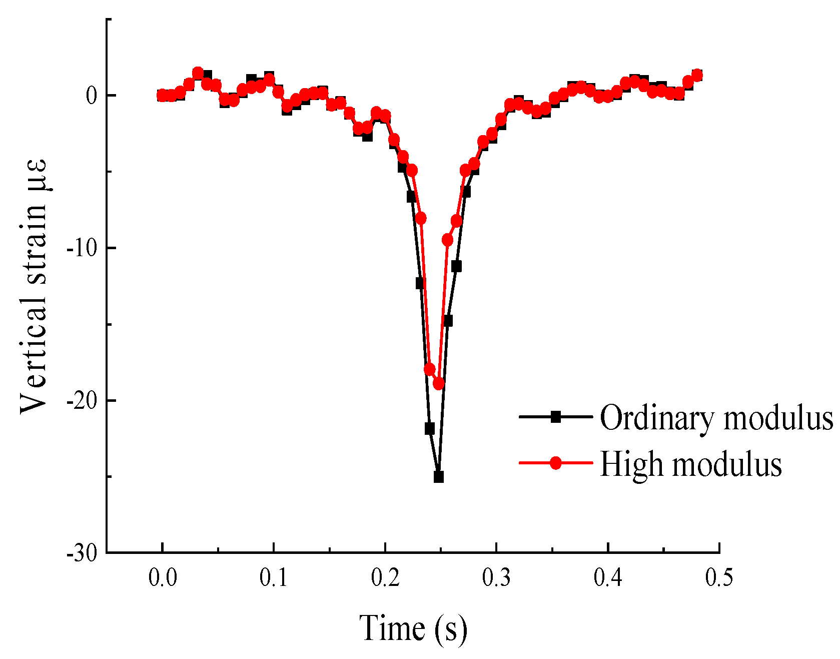
Under the action of moving loads, the pattern variations of the five parameters were essentially the same between the two types of pavement. Compared to conventional asphalt pavement, the vertical stress and vertical shear stress in HMAC pavement were larger, while the vertical strain, vertical shear strain, and vertical displacement were smaller. This is consistent with the conclusion of reference [
33,
34], which argued that the vertical stress of the upper surface layer of HMAC pavement is greater than that of conventional asphalt pavement.
The difference in the mechanical properties of HMAC pavement compared to conventional asphalt pavement are summarized as follows: the maximum vertical stress increased 7.96% from 326.11 kPa to 352.07 kPa; the strain value decreased 24.5% from −25.02 με to −18.89 με; and the vertical displacement decreased 18.8% from 0.16 mm to 0.13 mm. It can be seen that the HMAC pavement has good resistance to vertical deformation.
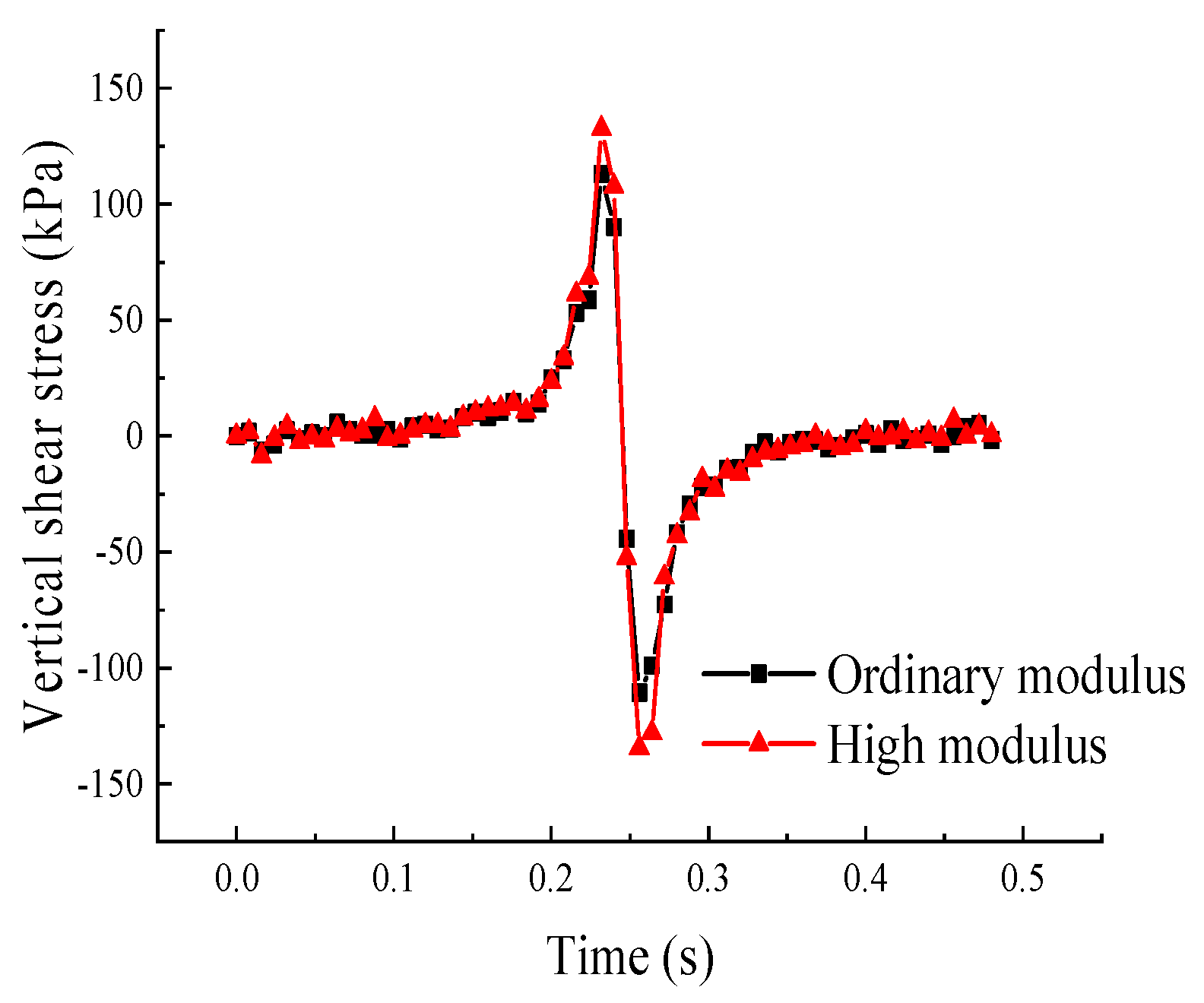
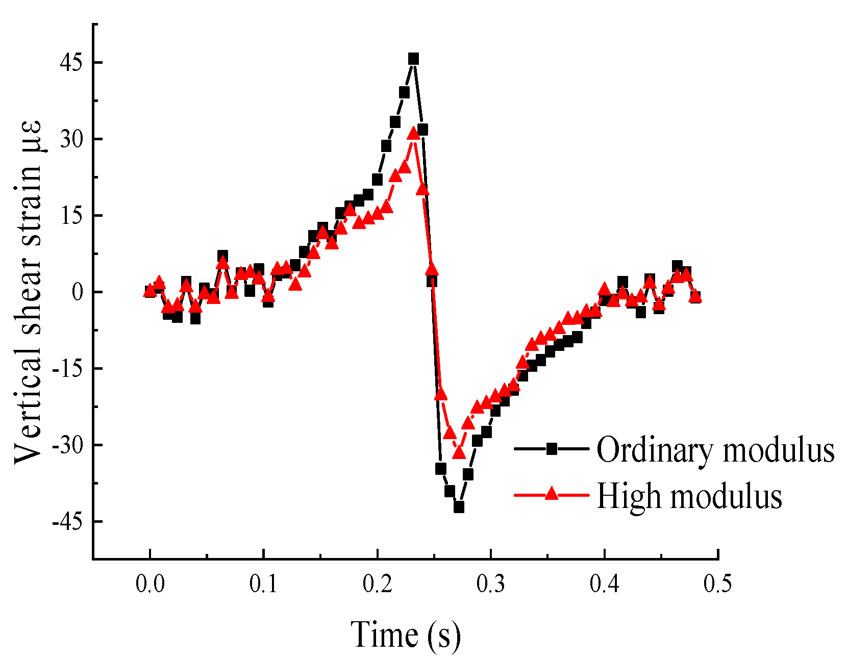
Both the shear stress and the shear strain changed abruptly before and after the load passed the point of interest. Before the vehicle moved over the loading point, the maximum vertical shear stress of the middle surface layer compared to the conventional surface layer increased from 117.96 kPa to 132.51 kPa, while the vertical shear strain decreased from 45.81 με to 30.80 με. These relationships show that HMAC can be used to reduce the strain deformation caused by shear stress and effectively prevent the shear damage of the pavement.
Although the use of HMAC increased the stress in the surface layers, the strain decreased, which indicated that the rutting resistance ability of the asphalt pavement improved.
4. Simulation of Temperature Field and Thermal Stress in HMAC Pavement
4.1. Analysis of Temperature Field
The following assumptions were made in the establishment of the temperature field model: (1) the pavement layers were homogeneous and isotropic continua; (2) the temperature gradient in the horizontal direction was zero, and only the transfer of heat flow in the vertical direction was considered; and (3) there was continuous contact between the layers of the pavement, and the temperature and heat flow between the layers was continuous.
The temperature parameters of each layer of pavement materials were obtained from related literature [
35,
36,
37,
38,
39]. The results are shown in
Table 7.
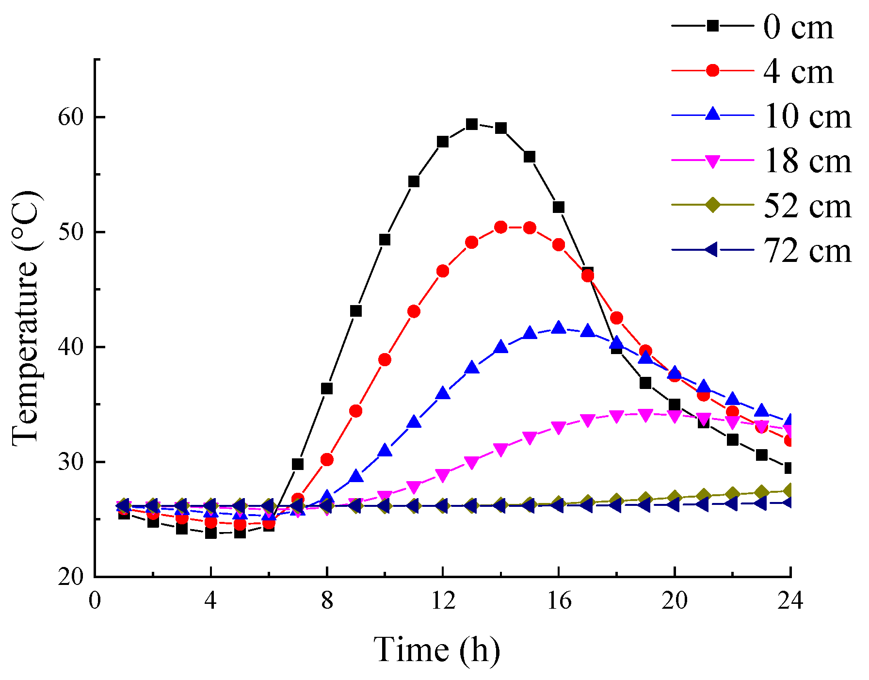
Air temperature data over a 24-h span in summer, as shown in
Table 8, was applied in ABAQUS to calculate the temperature field of HMAC pavement. The temperature changes of each structural layer over the 24-h period are shown in
Figure 8.
It can be seen from
Figure 8 that the temperature changes varied with different depths in the pavement structure. From this data, several conclusions were made.
The upper and middle surface layers were most affected by the outside air temperature, which was essentially the same as the variations of the air temperature. With increasing depth, the influence of outside air temperature gradually decreased. The temperature in the LFTB layer, which was least affected by the outside air temperature, always stayed at approximately 27 °C. When the outside air temperature reached its highest point, 38.1 °C at 14:00, the upper surface layer also reached the maximum value of approximately 59 °C. Due to the time delay of heat transfer, each structural layer reached the maximum temperature according to its depth beneath the surface, with the upper highest layer reaching the maximum temperature first. After 14:00, the temperature of each structural layer gradually decreased after reaching the maximum value. The road surface had the greatest overall change in temperature.
4.2. Analysis of Thermal Stress
With the periodic change in temperature, the stress due to thermal expansion and contraction in the pavement structure was calculated. In the calculation of the thermal stress, the temperature coefficients and elastic moduli were different at different temperatures, and the corresponding parameters of pavement materials were determined by the related literature [
40,
41,
42,
43,
44], as shown in
Table 9 and
Table 10. These parameters of the materials were automatically interpolated in ABAQUS according to the actual temperature at each point. The simulated thermal stress in different layers is shown in
Figure 9.
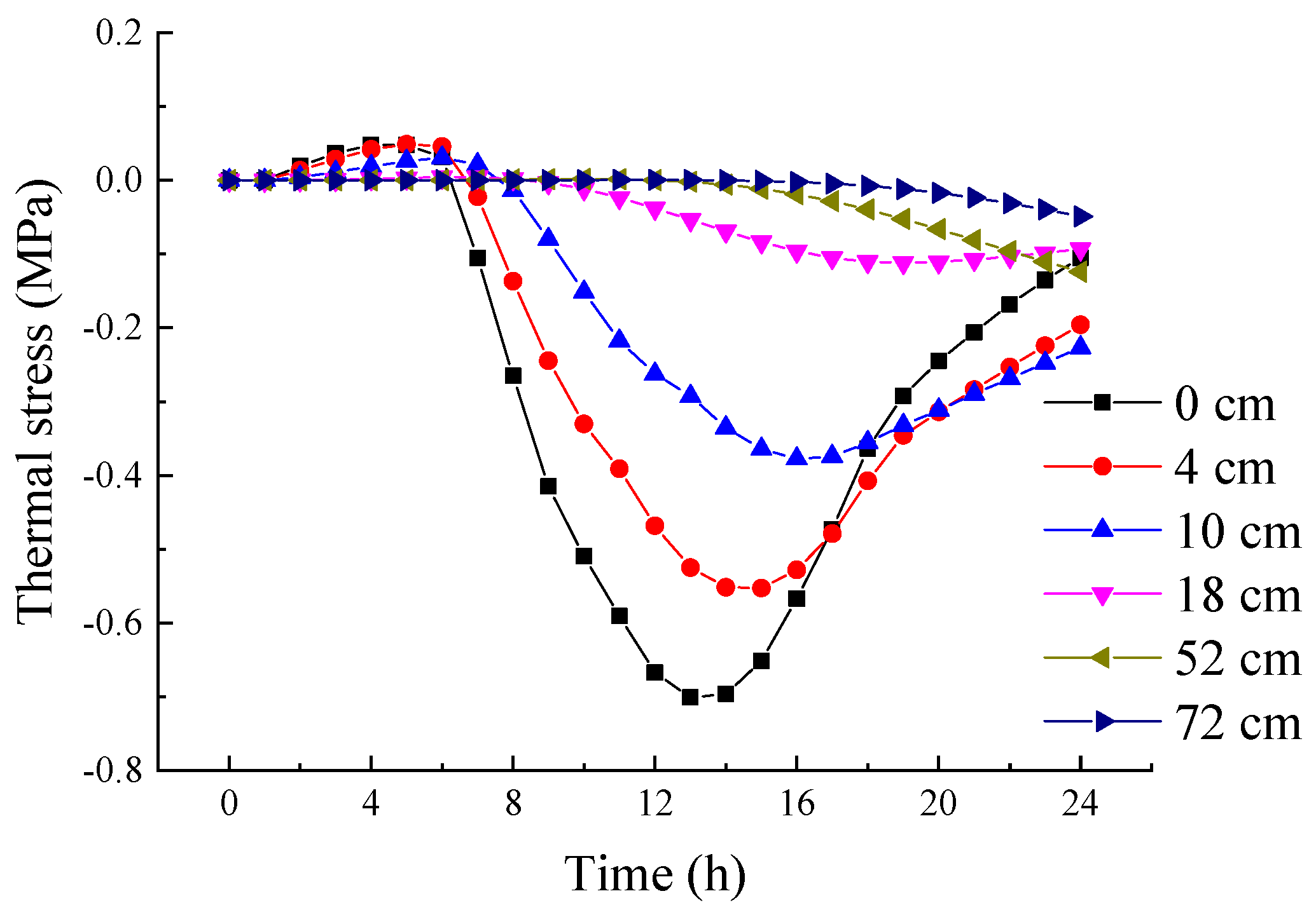
As shown in
Figure 9, because of the decreasing of air temperature, tensile stress was generated by the shrinkage of pavement materials and reached its peak at about 4:00 from 0:00 to 6:00. In contrast, the pavement material began to expand, and generated compressive stress with the gradual increasing of air temperature after 6:00. The maximum compressive stress was reached at the same time as the maximum temperature.
Since the surface layers were most affected by the outside air temperature, the temperature field in these layers had the greatest change over the time period; therefore, the thermal stress in the surface layers had the greatest range of values. The maximum thermal stress appeared on the surface of the pavement and had a value of −0.7 MPa. As the depth of the pavement increased, the thermal stress decreased continuously to approximately 0 in the base and sub-base layers. In hot summer, the maximum difference between tensile stress and compressive stress on the road surface within a day was about 0.75 MPa; the fatigue damage was easy accrued under the repeated action of thermal expansion and contraction.
Therefore, high temperature had a great impact on asphalt pavement, especially in the summer afternoon, during which the maximum temperature of the pavement surface almost reached 60 °C. Such temperatures will lead to the softening of asphalt pavement and the change of material properties; coupled with the repeating and heavy loading, fatigue damage could occur easily, which is also an important factor for rutting in the high-temperature season.
5. Anti-Rutting Analysis of HMAC Pavement under Continuous Temperature Variation
Rutting is generated by the combination of driving load and external environment. Based on a time-hardening creep model, the previously generated temperature field was introduced to analyze the formation process of rutting, and the rutting model was established under the condition of continuous temperature variation. By comparing the creep and permanent deformation of HMAC pavement with those of conventional asphalt pavement under moving loads, the rutting resistance characteristics of HMAC pavement were studied.
5.1. The Establishment of Rutting Calculation Model
The deformation of asphalt pavement includes creep deformation and elastic deformation. Rutting is a severe road distress that is mainly caused by the creep deformation [
45]. In this study, the time-hardening creep model was used to simulate the rutting.
The creep deformation of pavement (
) is related to the temperature (
T), stress (
q), and time (
t), and was obtained from Equation (1):
In this study, the Norton Bailey creep law was applied to simulate the creep characteristics of asphalt mixture under loading conditions. In the analysis process, the stress is assumed to be constant; as a result, the above equation can be expressed as:
where
q and
t refer to the stress and time, respectively; meanwhile,
C1,
C2, and
C3 are the temperature-dependent model parameters, and were determined based on the lab tests.
Furthermore, Equation (2) can be expressed as:
Equation (3) is the time–stress–creep model of ABAQUS, in which
A,
m, and
n are the model parameters:
In order to simulate road rutting, the creep parameters of the asphalt surface layers were used in the model. The selected parameter values are shown in
Table 11, based on references [
45,
46,
47,
48,
49].
In the analysis step module, 24 analysis steps, step-1 h through step-24 h, were set. These step srepresented 24 hours in a day. In order to simulate the formation of rutting of asphalt pavement during a continuous temperature change in one day, the cumulative loading time of the pavement structure needed to be input into each analysis step. The cumulative loading time of the wheel load was calculated as follows:
where
(s) is the cumulative loading time of the wheel load;
is the number of wheel-loading cycles;
(kN) is the axle weight of the vehicle;
is number of tires on the axle;
(MPa) is the tire contact pressure;
(cm) is the width of tire–ground contact; and
(km/h) is driving speed.
According to the above formula, the required calculation parameters were determined, as shown in
Table 12.
Substituting the above parameters into Formula (5), it can be calculated that the time during which a one-wheel load acts on the road surface is 0.01006 s, and the cumulative loading time for 500,000-axle loads is 5030 s. A traffic volume distribution of a certain section of road over 24 hours was selected, and an approximated value of the segmented cumulative loading time of each hour in one day was obtained, as shown in
Table 13.
Two load belts were installed in the middle of the road surface to apply the moving load. In order to calculate the road rutting, the previously calculated temperature field data were introduced in each analysis step by editing the INP file in ABAQUS.
5.2. Analysis of Creep Deformation at Different Depths of Pavement Structure
Rutting is mainly caused by the internal compaction and deformation of the asphalt pavement structure. Therefore, in order to further study the deformation of each structural layer, the distribution of transverse and vertical creep strain at different depths underneath the wheel center point (because of symmetry, the leftmost wheel was selected) and the point directly between the left-side wheels (hereafter: “dual-wheel center”) were studied. These points were referred to in
Figure 2 as point B and point A, respectively. The results are shown in
Figure 10 and
Figure 11.
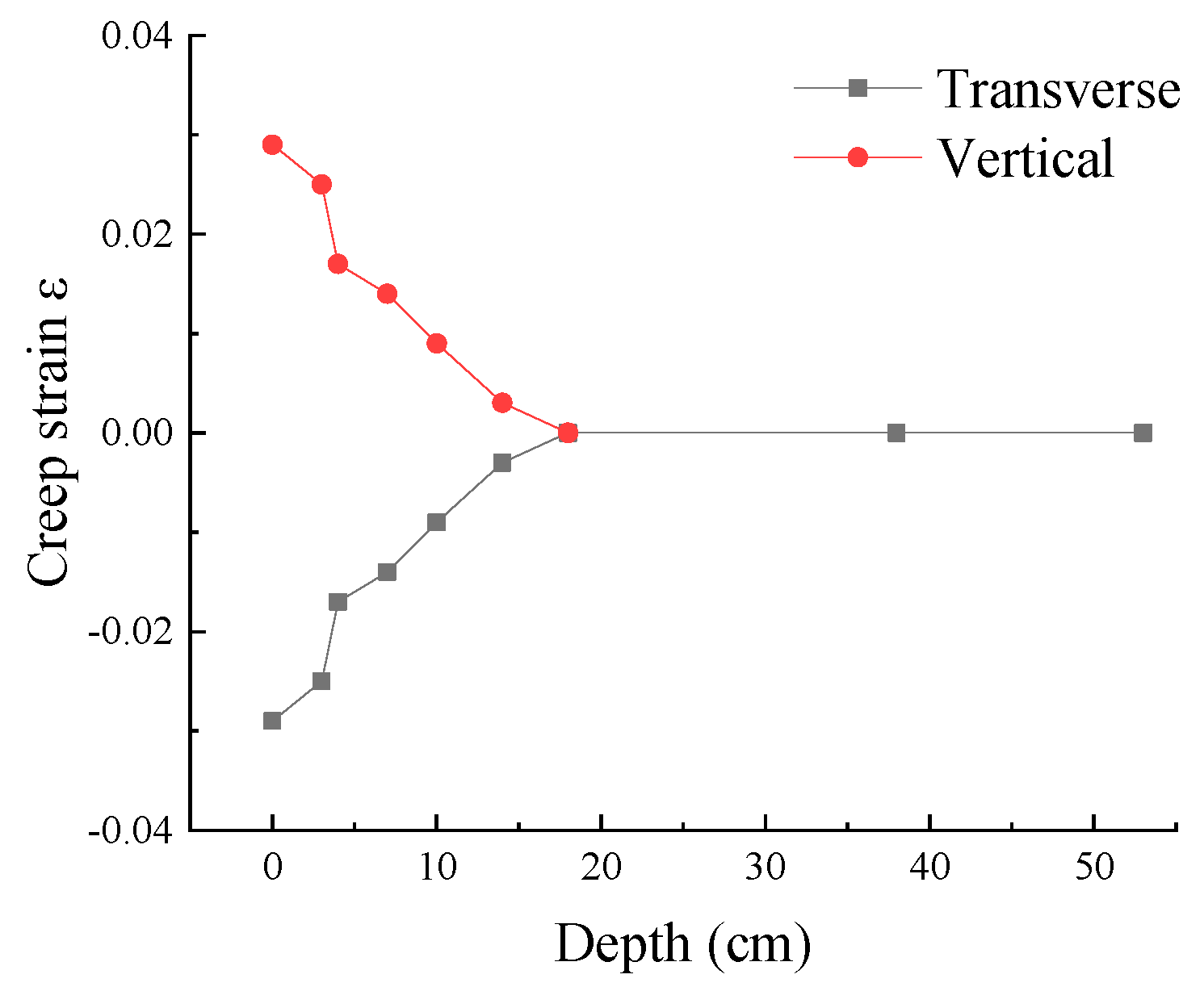
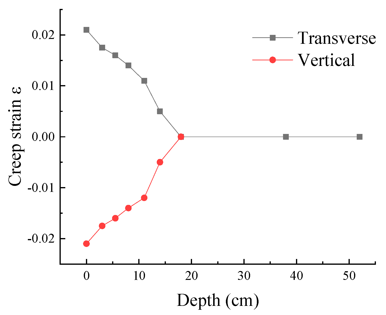
As shown in
Figure 10 and
Figure 11, the lateral and vertical creep strain of the structural layers underneath the road surface decreased with increasing depth, and were reduced to zero at 18 cm. This means that the creep deformation only occurred in the surface layers. The maximum vertical and transverse creep strains were almost the same, and both appeared on the road surface. The maximum creep strain underneath the center of the leftmost wheel and the dual-wheel center were 0.021 and 0.028 respectively, and the pattern variations were consistent throughout the depth of the road.
At each reference point, the vertical creep and transverse creep had opposite signs. The vertical creep strain on the road surface below the leftmost wheel center was negative, which means compressive strain; meanwhile, the horizontal creep strain was positive, which means tensile strain. In contrast, the vertical creep strain on the road surface below the dual-wheel center was tensile strain, and the horizontal creep strain was a compressive strain.
5.3. Comparison of Rutting Resistance between HMAC and Conventional Asphalt Pavement
5.3.1. Comparison of Permanent Deformation of Surface Layers
In order to further analyze the rutting resistance performance of HMAC, the permanent deformation was simulated for both HMAC and conventional asphalt pavement. The material parameters of the middle surface layer in conventional asphalt pavement are shown in
Table 14. The permanent deformations are shown in
Table 15 and
Figure 12,
Figure 13 and
Figure 14.
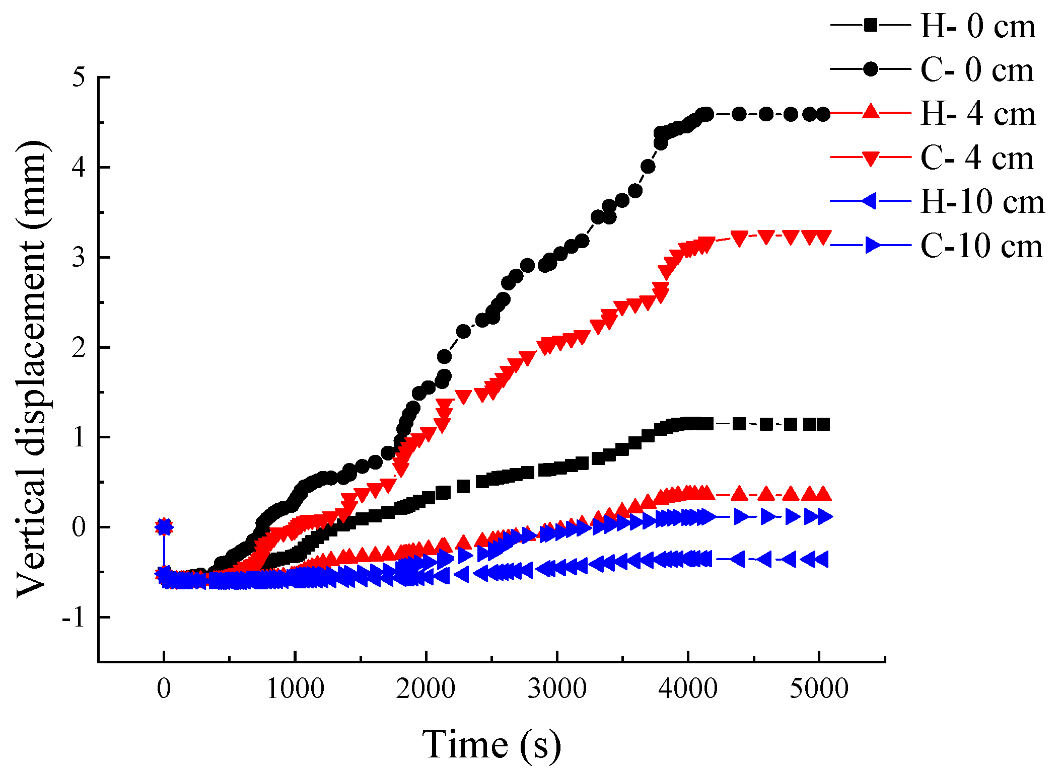
As shown in
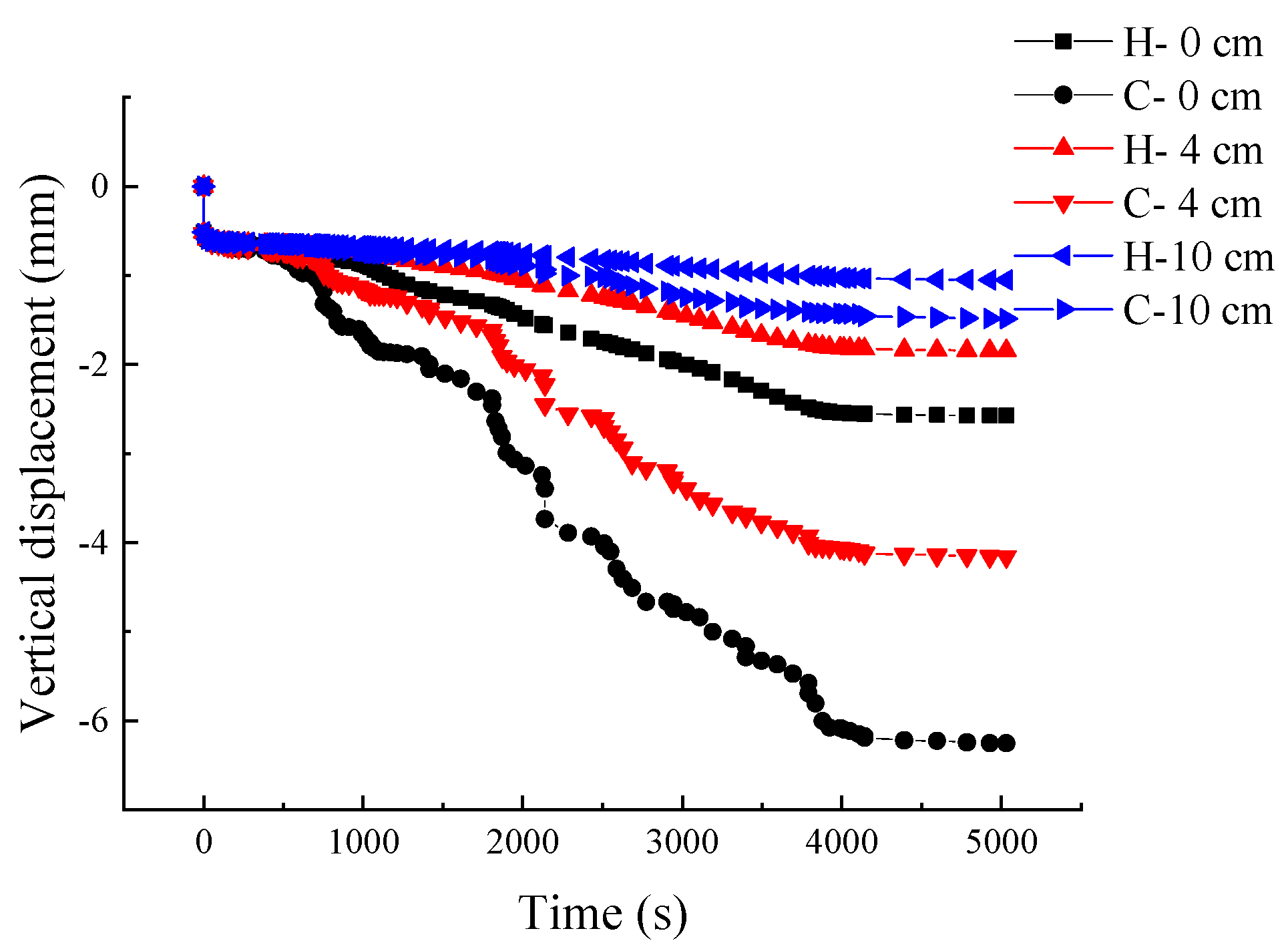
Figure 12 and
Figure 13, the internal deformation of conventional asphalt pavement changed with the increase of cumulative vehicle loading time, and its pattern variations were consistent with HMAC pavement. However, in the continuous temperature changing condition, the deformation curve of HMAC pavement fluctuated less with time and temperature, which was due to the low sensitivity of high modulus asphalt materials to temperature fluctuations. Therefore, the use of HMAC can reduce damage to the road surface caused by temperature changes.
Under continuous loading, with increasing depth, the difference in vertical displacement between HMAC pavement and conventional asphalt pavement decreased. The internal deformation of the conventional asphalt pavement increased at a faster rate, resulting in a larger difference with the permanent deformation of the HMAC pavement, and the deformation value of both permanent tended to be stable after 4000 s.
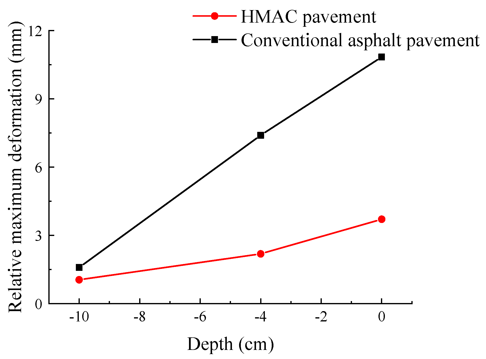
From
Table 15 and
Figure 14, it can be seen that the deformation values of the conventional asphalt pavement at different depths were much higher than those of the HMAC pavement. At the road surface, the maximum relative deformation of conventional asphalt pavement was 10.84 mm, which was 7.13 mm higher than that of HMAC, and the difference in deformation values was the largest. The second-highest difference in deformation was 5.21 mm at the bottom of the upper surface layer. At a depth of 10 cm, although the vertical deformation was small, the maximum relative deformation of the conventional asphalt pavement was 1.59 mm. This was an increase of 51.4%compared to the HMAC pavement. Therefore, the HMAC material can significantly reduce the permanent deformation of pavement.
In the conventional asphalt pavement, the maximum relative deformation generated in the middle surface layer was the largest, at 5.81 mm. Therefore, the HMAC layer that was located in the middle surface layer could effectively reduce the relative deformation. Simultaneously, the deformation rate of the upper surface layer was also greatly reduced, thereby reducing the permanent deformation of the entire pavement.
To summarize, the permanent deformation of the two pavement structures mainly occurred in the upper and middle surface layers, while the settlement of HMAC in middle surface layer could effectively decrease the permanent deformation.
5.3.2. Comparison of Permanent Pavement Deformation under Heavy Traffic
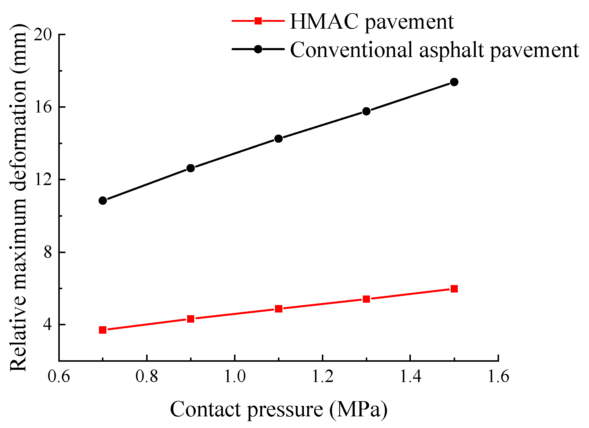
Heavy traffic is a main cause for permanent deformation and the rutting distress of asphalt pavement. In order to further study the rutting resistance performance of HMAC pavement, a series of vehicle loads were applied to analyze the deformation of the two types of pavement. The result of this test is shown in
Figure 15.
From
Figure 15, it can be seen that as the tire contact pressure increased from 0.7 MPa to 1.5 MPa, the maximum relative deformation in both HMAC pavement and conventional asphalt pavement significantly increased; however, the maximum relative deformation of conventional asphalt pavement increased faster. When the tire contact pressure was 0.7 MPa, the maximum deformation of the conventional asphalt pavement was 7.13 mm higher than that of HMAC, and this value increased to 11.4 mm when the tire contact pressure was 1.5 MPa. Therefore, a heavy load is more harmful to the conventional pavement structure; HMAC pavement can effectively resist road deformation caused by heavy-duty loading and hot weather.
6. Summary and Conclusions
Based on the viscoelastic theory of asphalt, the finite element model in software ABAQUS was established according to the pavement structure and the material properties of the HMAC, the stress field and the temperature field was analyzed; then, the creep behavior and permanent deformation of the HMAC pavement was achieved. The following conclusions were obtained:
1. Compared to conventional asphalt pavement, vertical stress and shear stress generated in HMAC pavement increased, while the vertical strain, shear strain, and vertical displacement decreased. The vertical strain and the shear strain decreased by 24.5% and 32.8% respectively. The vertical displacement that was generated in the HMAC road surface also reduced from 0.16 mm to 0.13 mm; this is an 18.8% reduction, which improved the evenness of the road surface.
2. The pattern variations of the temperature field and the thermal stress were consistent. When the surface temperature reached the maximum of 59 °C, the maximum thermal stress of −0.7 MPa was found. As the depth increased, the influence of outside air temperature on the pavement structural layers gradually decreased.
3. In both the HMAC pavement and conventional asphalt pavement, the creep deformation only occurred in the asphalt surface layers. At the road surface, the maximum relative deformation of conventional asphalt pavement reached 10.84 mm, which was 7.13 mm higher compared to that of HMAC pavement. Therefore, the HMAC layer could effectively reduce the relative deformation of pavement.
4. With the increase of tire contact pressure from 0.7 MPa to 1.5 MPa, the maximum relative deformation increased by 2.27 mm and 6.54 mm in HMAC pavement and conventional asphalt pavement, respectively. This suggested that HMAC pavement had better resistance to road deformation and rutting.


 ,
, 


