An Interdisciplinary Approach to the Nanomanipulation of SiO2 Nanoparticles: Design, Fabrication and Feasibility

 ,
,  ,
,  , ,
, ,  ,
,  , ,
, ,  , and
, and 
Abstract
1. Introduction
2. Synthesis and Characterization of the Nanoparticles
2.1. Properties and Applications
2.2. Synthesis and Experimental Methods
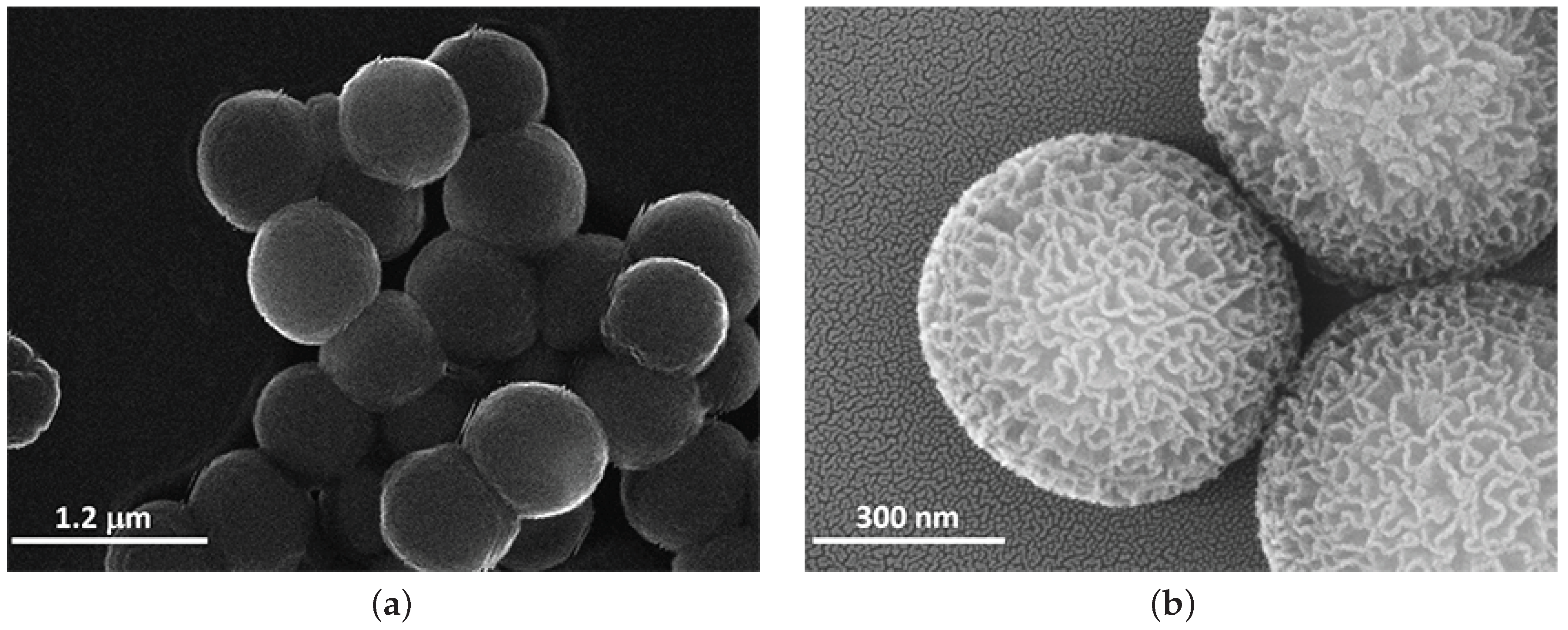
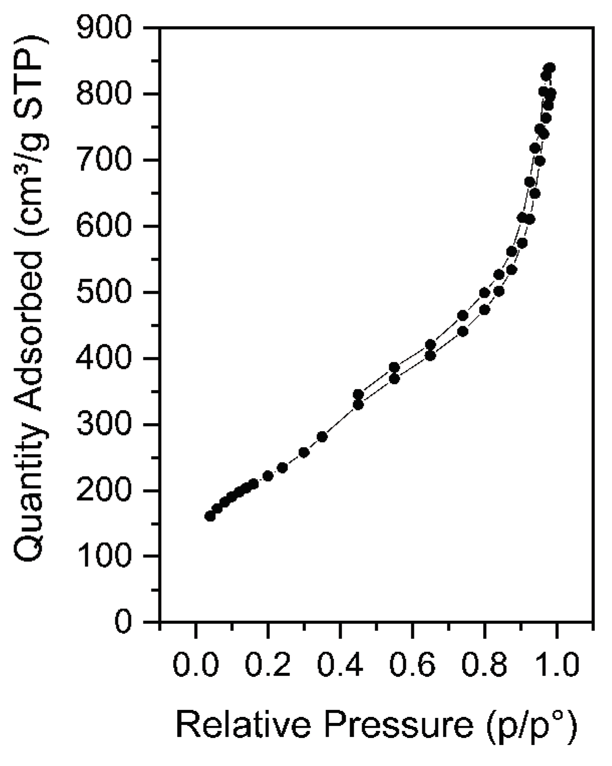
2.3. Morphological Characterization
3. Design and Fabrication of the Nanomanipulator
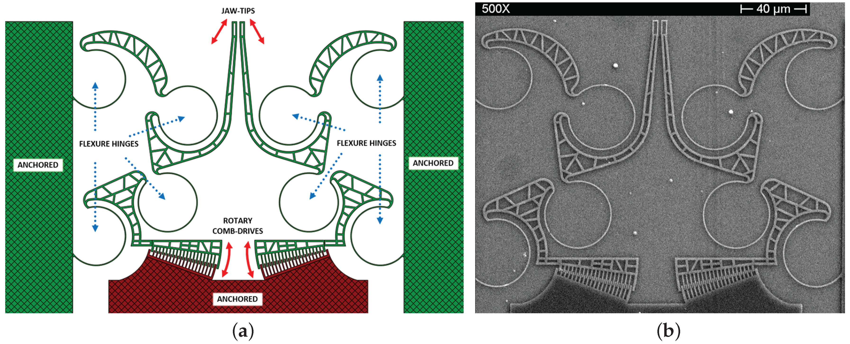
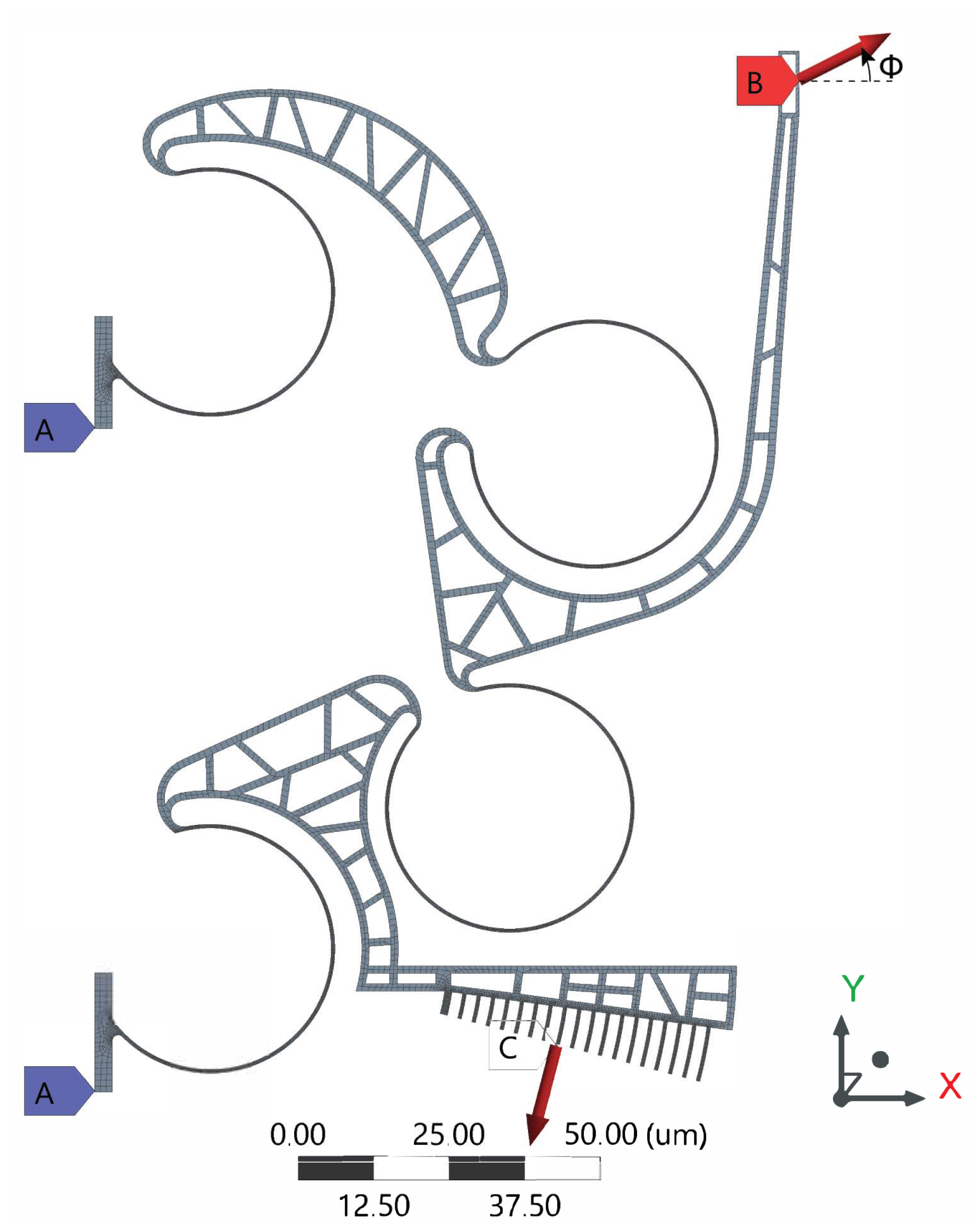
3.1. Design
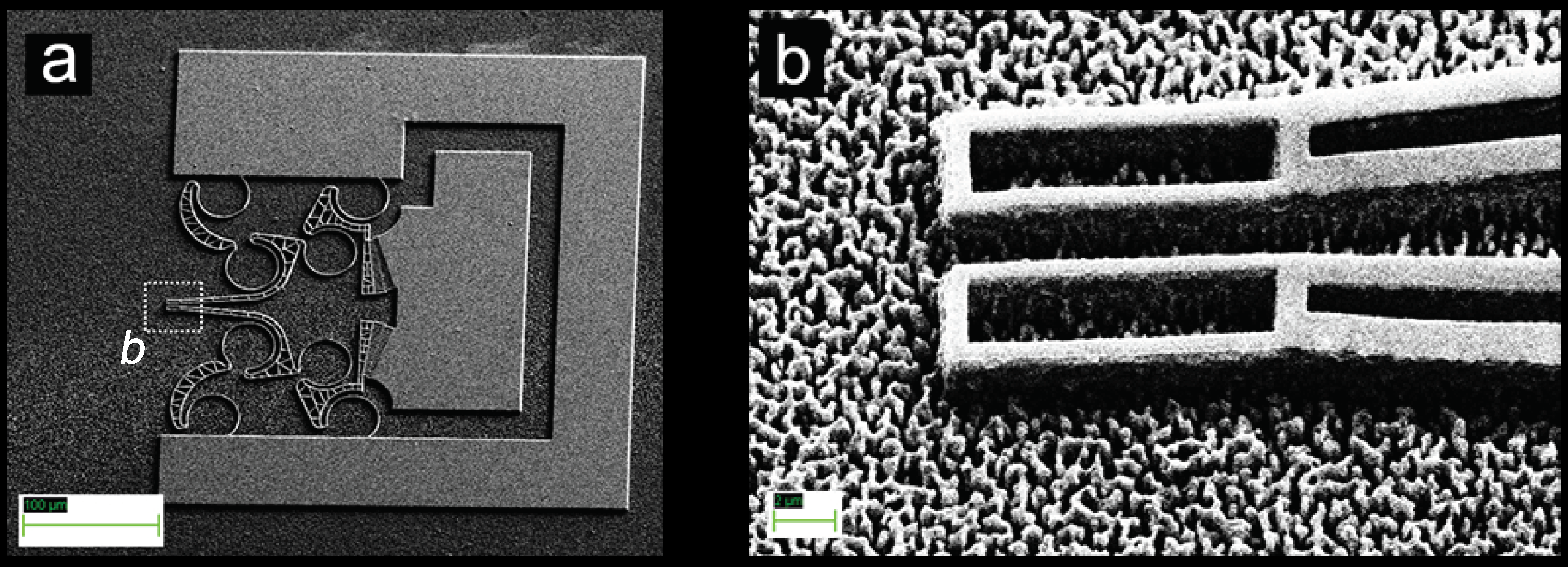
3.2. Fabrication
- The smallest geometric dimension of the system was the width of the comb-drive fingers (600 nm); in order to reach it, a sub-micrometric lithographic resolution is required: the geometries definition was carried out using Electron Beam Lithography (EBL) on an e-resist polymeric film [44].
- Highly versatile materials, suitable for low-cost and low-energy fabricated systems, such as hydrogenated amorphous silicon (a-Si:H) and Indium Tin Oxide (ITO), were investigated for the device mainframe: the main goal was to achieve a system that can be biologically compatible and, at the same time, monolithically integrable even on flexible and polymeric substrates [45,46,47,48,49,50,51]. Dry etching methods, such as sputter-etching and Reactive Ion Etching (RIE), for the structural layer patterning were adopted, using a metal as a masking layer, such as chromium or aluminum.
- An intermediate sacrificial layer between the substrate and the structural layer must be considered: its selective removal after completing the mainframe patterning phase assures the achievement of a structure partially suspended from the substrate. The wet etching procedure offers both isotropic and selective removal of a determined material; furthermore, “etch holes: in the mainframe were specifically designed as under-etching promoters for the rigid suspended body of the system.
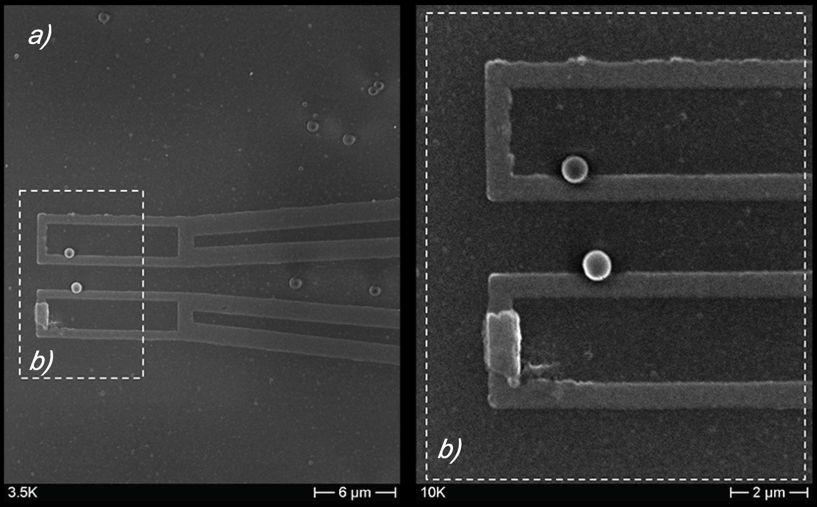
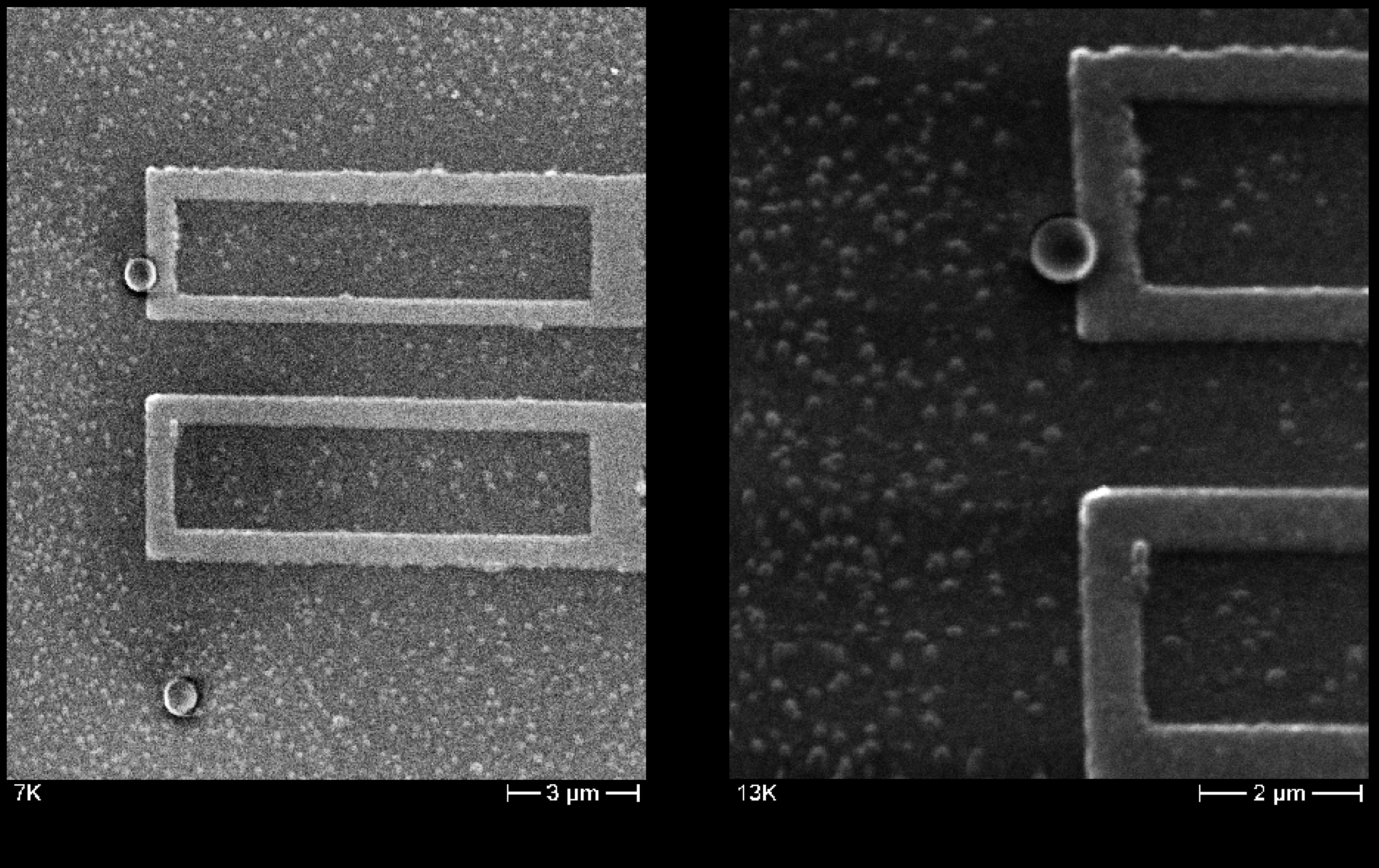
4. Tip-to-Particle Contact Tests
5. Feasibility Study Based on FEA Simulation
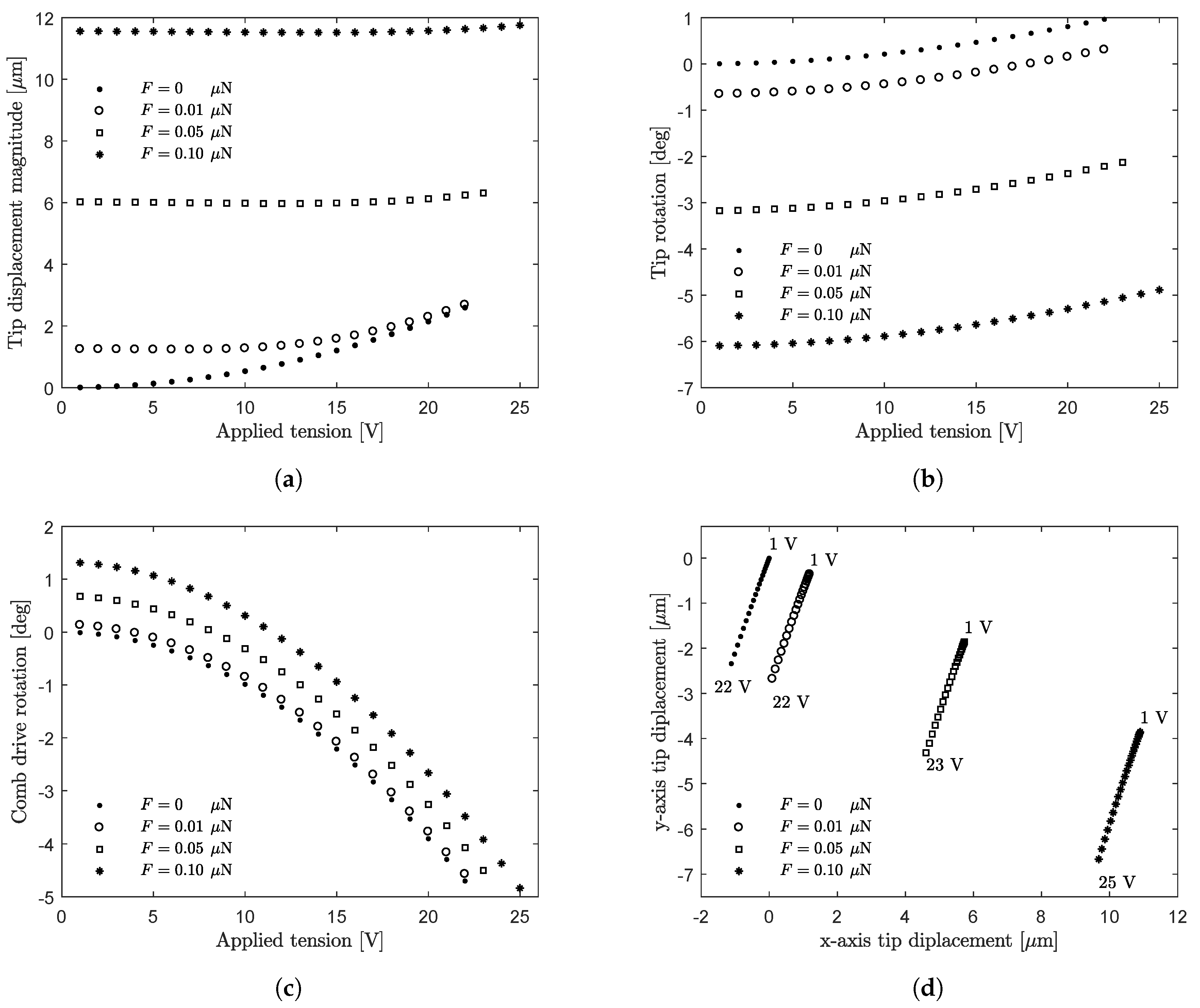
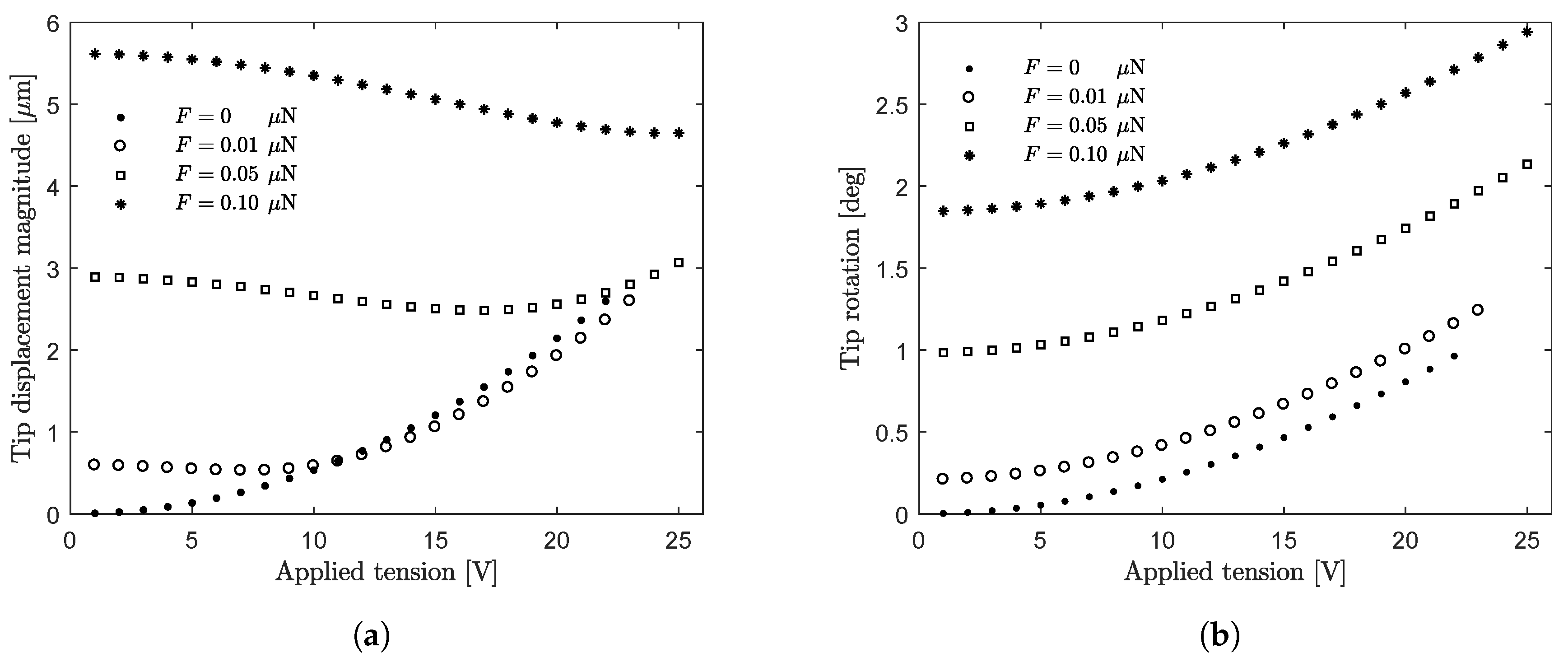
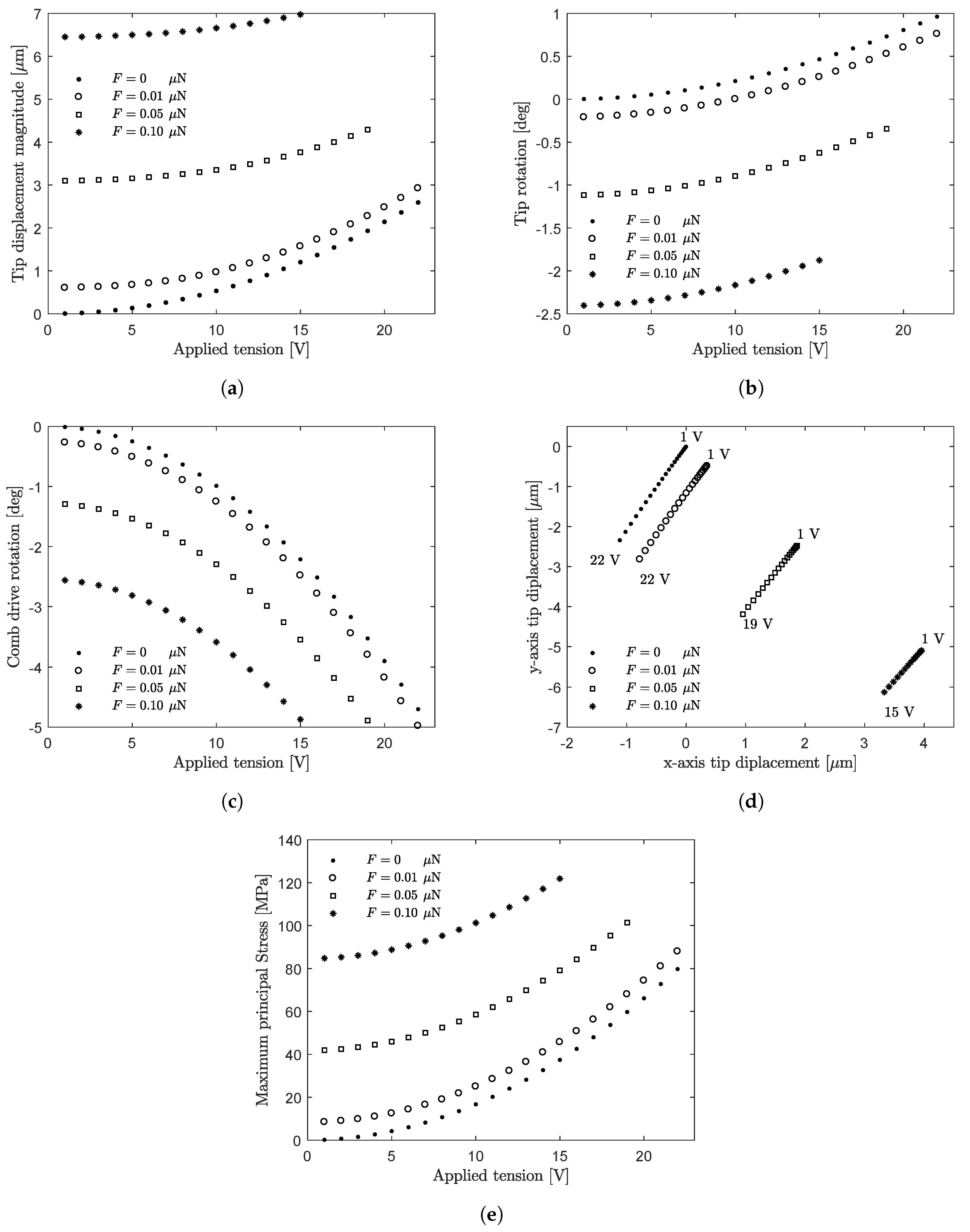
- the tip displacement magnitude increases (Figure 8a); only for the lowest value of the force ( μN) and for high tension values (>20 V), the tip displacement magnitude is close to the case ;
- the tip rotation (magnitude) increases (Figure 8b);
- the applied tension required to achieve the maximum rotation of the comb-drive increases (from 22 V for to 25 V for μN; Figure 8c);
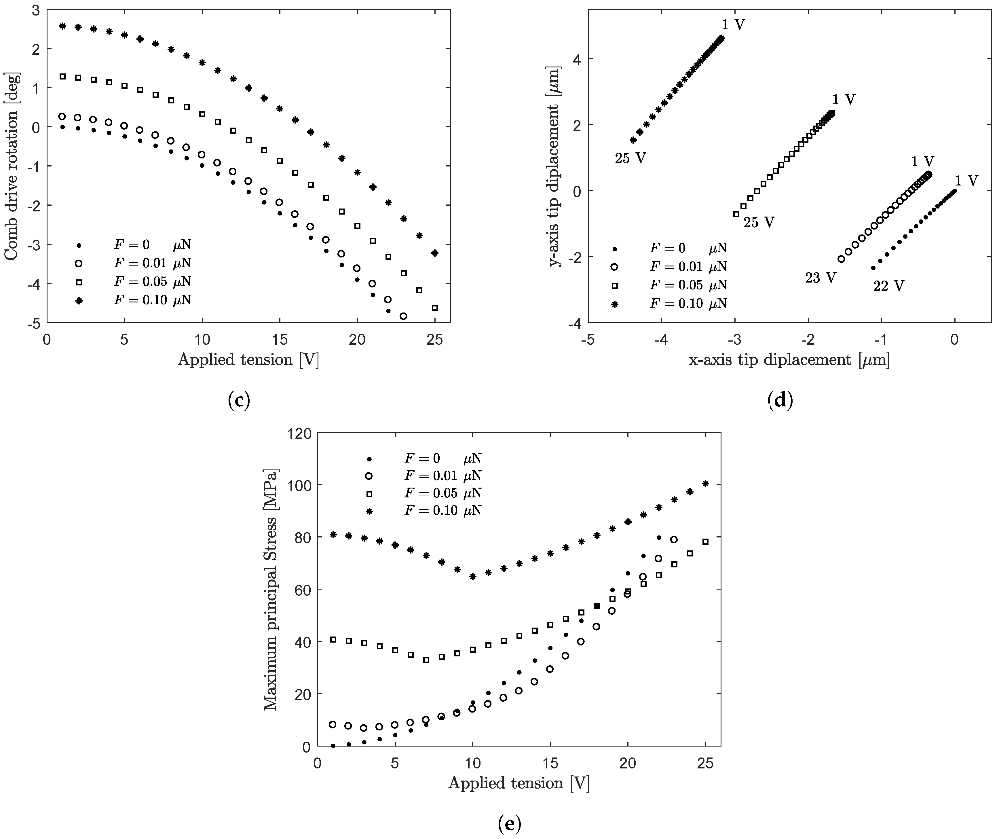
- the tip displacement shifts increasingly along the positive direction of the x-axis (Figure 8d);
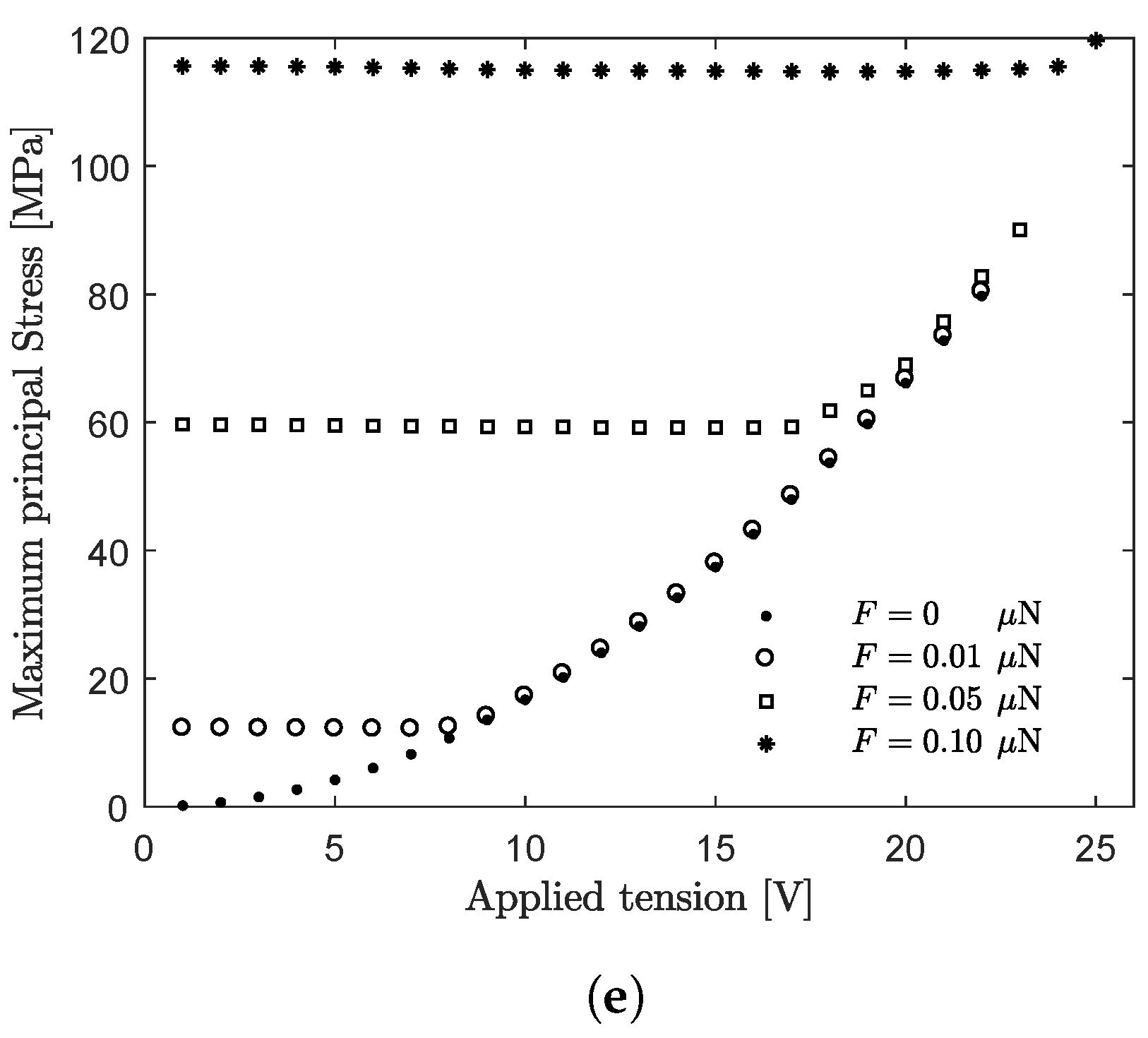
- the maximum principal stress increases for all the applied tension values only for the highest value of the force magnitude ( μN). The force magnitudes μN and μN give the predominant contribution to the MPSuntil the applied tension does not exceed about 20 V and 9 V, respectively (Figure 8e).
- the tip rotation increases (Figure 9b);
- the applied tension required to achieve the maximum rotation of the comb-drive increases (from 22 V for to 25 V for μN, Figure 9c);
- the tip displacement shifts increasingly along the negative direction of the x-axis (Figure 9d);
- the maximum principal stress generally increases, but depends on the applied tension values (Figure 9e).
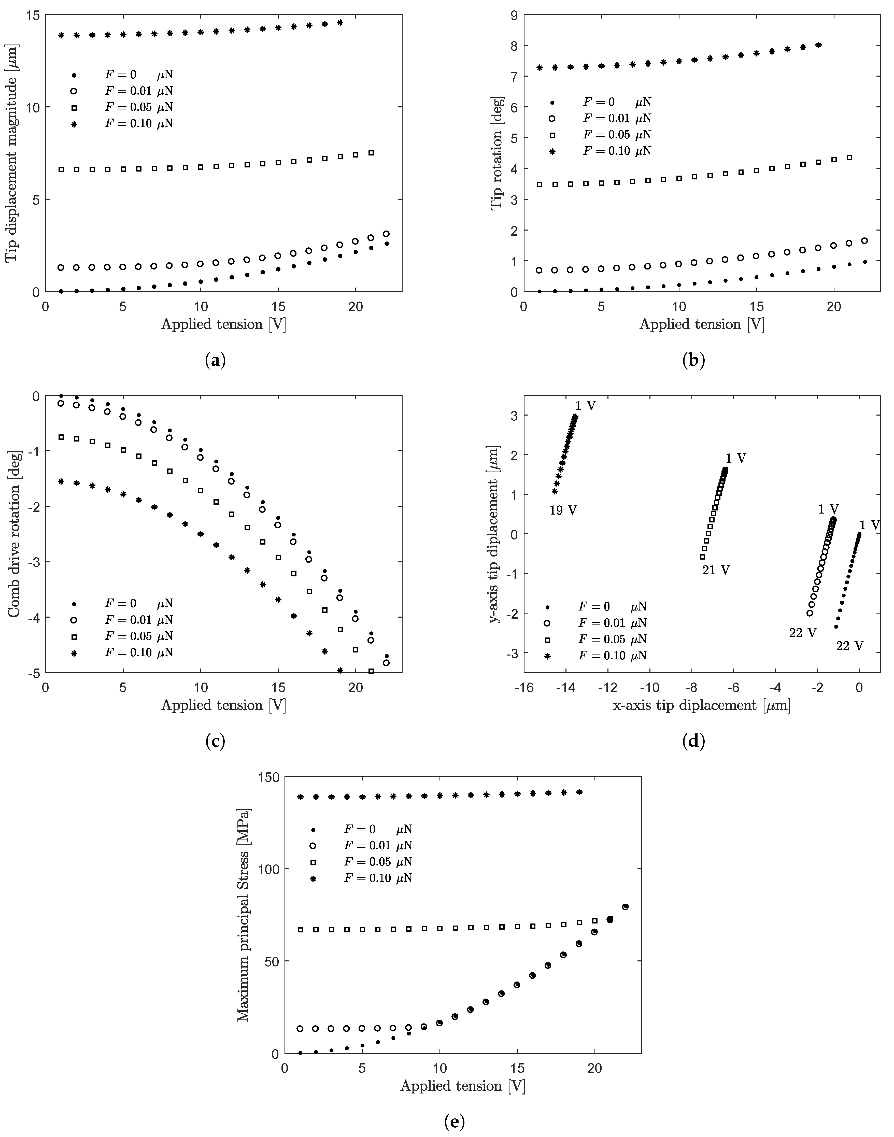
- the tip displacement magnitude increases (Figure 10a);
- the tip rotation increases (Figure 10b);
- the applied tension required to achieve the maximum rotation of the comb-drive decreases (from 22 V for to 19 V for μN, Figure 10c);
- the tip displacement shifts increasingly along the negative direction of the -axis (Figure 10d);
- the maximum principal stress increases (for μN and for μN). The force magnitude μN gives the predominant contribution to the MPS until the applied tension does not exceed about 8 V (Figure 10e).
- the tip displacement magnitude increases (Figure 11a);
- the tip rotation (magnitude) increases (Figure 11b);
- the applied tension required to achieve the maximum rotation of the comb-drive decreases (from 22 V for to 15 V for μN, Figure 11c);
- the tip displacement shifts increasingly along the positive direction of the x-axis (Figure 11d);
- the maximum principal stress increases (Figure 11e).
6. Conclusions
Author Contributions
Funding
Acknowledgments
Conflicts of Interest
References
- Gad-el Hak, M.E. (Ed.) The MEMS Handbook, 2nd ed.; Mechanical and Aerospace Engineering Series, 3 Volume Set; CRC Press, Tayor and Francis Group: Boca Raton, FL, USA, 2005. [Google Scholar]
- Bhushan, B.E. (Ed.) Springer Handbook of Nanotechnology; Springer: Berlin, Germany, 2017. [Google Scholar]
- Marano, D.; Cammarata, A.; Fichera, G.; Sinatra, R.; Prati, D. Modeling of a three-axes MEMS gyroscope with feedforward PI quadrature compensation. In Advances on Mechanics, Design Engineering and Manufacturing; Lecture Notes in Mechanical Engineering; Springer: Cham, Switzerland, 2017; pp. 71–80. [Google Scholar]
- Belfiore, N.P.; Simeone, P. Inverse kinetostatic analysis of compliant four-bar linkages. Mech. Mach. Theory 2013, 69, 350–372. [Google Scholar] [CrossRef]
- Balucani, M.; Belfiore, N.P.; Crescenzi, R.; Genua, M.; Verotti, M. Developing and modeling a plane 3 DOF compliant micromanipulator by means of a dedicated MBS code. In Proceedings of the 2011 NSTI Nanotechnology Conference and Expo, NSTI-Nanotech 2011, Boston, MA, USA, 13–16 June 2011; Volume 2, pp. 659–662. [Google Scholar]
- Balucani, M.; Belfiore, N.P.; Crescenzi, R.; Verotti, M. The development of a MEMS/NEMS-based 3 D.O.F. compliant micro robot. Int. J. Mech. Control 2011, 12, 3–10. [Google Scholar]
- Belfiore, N.P.; Balucani, M.; Crescenzi, R.; Verotti, M. Performance analysis of compliant mems parallel robots through pseudo-rigid-body model synthesis. In Proceedings of the ASME 2012 11th Biennial Conference on Engineering Systems Design and Analysis, Nantes, France, 2–4 July 2012; Volume 3, pp. 329–334. [Google Scholar]
- Belfiore, N.P.; Emamimeibodi, M.; Verotti, M.; Crescenzi, R.; Balucani, M.; Nenzi, P. Kinetostatic optimization of a MEMS-based compliant 3 DOF plane parallel platform. In Proceedings of the ICCC 2013—IEEE 9th International Conference on Computational Cybernetics, Tihany, Hungary, 8–10 July 2013; pp. 261–266. [Google Scholar]
- Verotti, M.; Crescenzi, R.; Balucani, M.; Belfiore, N.P. MEMS-based conjugate surfaces flexure hinge. J. Mech. Des. Trans. ASME 2015, 137, 012301. [Google Scholar] [CrossRef]
- Belfiore, N.P.; Broggiato, G.; Verotti, M.; Balucani, M.; Crescenzi, R.; Bagolini, A.; Bellutti, P.; Boscardin, M. Simulation and construction of a mems CSFH based microgripper. Int. J. Mech. Control 2015, 16, 21–30. [Google Scholar]
- Crescenzi, R.; Balucani, M.; Belfiore, N.P. Operational characterization of CSFH MEMS technology based hinges. J. Micromech. Microeng. 2018, 28, 055012. [Google Scholar] [CrossRef]
- Yamahata, C.; Collard, D.; Legrand, B.; Takekawa, T.; Kumemura, M.; Hashiguchi, G.; Fujita, H. Silicon nanotweezers with subnanometer resolution for the micromanipulation of biomolecules. J. Microelectromech. Syst. 2008, 17, 623–631. [Google Scholar] [CrossRef]
- Sardan, O.; Petersen, D.H.; Molhave, K.; Sigmund, O.; Boggild, P. Topology optimized electrothermal polysilicon microgrippers. Microelectron. Eng. 2008, 85, 1096–1099. [Google Scholar] [CrossRef]
- Zubir, M.N.M.; Shirinzadeh, B.; Tian, Y. A new design of piezoelectric driven compliant-based microgripper for micromanipulation. Mech. Mach. Theory 2009, 44, 2248–2264. [Google Scholar] [CrossRef]
- Chu, J.; Zhang, R.; Chen, Z. A novel SU-8 electrothermal microgripper based on the type synthesis of the kinematic chain method and the stiffness matrix method. J. Micromech. Microeng. 2011, 21, 054030. [Google Scholar] [CrossRef]
- Wang, D.; Yang, Q.; Dong, H. A Monolithic Compliant Piezoelectric-Driven Microgripper: Design, Modeling, and Testing. IEEE/ASME Trans. Mechatron. 2013, 18, 138–147. [Google Scholar] [CrossRef]
- Di Giamberardino, P.; Bagolini, A.; Bellutti, P.; Rudas, I.; Verotti, M.; Botta, F.; Belfiore, N. New MEMS tweezers for the viscoelastic characterization of soft materials at the microscale. Micromachines 2017, 9, 15. [Google Scholar] [CrossRef] [PubMed]
- Bagolini, A.; Ronchin, S.; Bellutti, P.; Chistè, M.; Verotti, M.; Belfiore, N.P. Fabrication of Novel MEMS Microgrippers by Deep Reactive Ion Etching With Metal Hard Mask. J. Microelectromech. Syst. 2017, 26, 926–934. [Google Scholar] [CrossRef]
- Dochshanov, A.; Verotti, M.; Belfiore, N. A Comprehensive Survey on Microgrippers Design: Operational Strategy. J. Mech. Des. Trans. ASME 2017, 139, 070801. [Google Scholar] [CrossRef]
- Verotti, M.; Dochshanov, A.; Belfiore, N.P. A Comprehensive Survey on Microgrippers Design: Mechanical Structure. J. Mech. Des. Trans. ASME 2017, 139, 060801. [Google Scholar] [CrossRef]
- Verotti, M.; Dochshanov, A.; Belfiore, N.P. Compliance Synthesis of CSFH MEMS-Based Microgrippers. J. Mech. Des. Trans. ASME 2017, 139, 022301. [Google Scholar] [CrossRef]
- Potrich, C.; Lunelli, L.; Bagolini, A.; Bellutti, P.; Pederzolli, C.; Verotti, M.; Belfiore, N.P. Innovative silicon microgrippers for biomedical applications: Design, mechanical simulation and evaluation of protein fouling. Actuators 2018, 7, 12. [Google Scholar] [CrossRef]
- Veroli, A.; Buzzin, A.; Crescenzi, R.; Frezza, F.; de Cesare, G.; D’Andrea, V.; Mura, F.; Verotti, M.; Dochshanov, A.; Belfiore, N.P. Development of a NEMS-technology based nano gripper. Mech. Mach. Sci. 2018, 49, 601–611. [Google Scholar]
- Veroli, A.; Buzzin, A.; Frezza, F.; de Cesare, G.; Hamidullah, M.; Giovine, E.; Verotti, M.; Belfiore, N. An Approach to the Extreme Miniaturization of Rotary Comb Drives. Actuators 2018, 7, 70. [Google Scholar] [CrossRef]
- Yin, J.; Retsch, M.; Lee, J.H.; Thomas, E.L.; Boyce, M.C. Mechanics of nanoindentation on a monolayer of colloidal hollow nanoparticles. Langmuir 2011, 27, 10492–10500. [Google Scholar] [CrossRef]
- Wampler, H.P.; Ivanisevic, A. Nanoindentation of gold nanoparticles functionalized with proteins. Micron 2009, 40, 444–448. [Google Scholar] [CrossRef]
- Zou, M.; Yang, D. Nanoindentation of silica nanoparticles attached to a silicon substrate. In Proceedings of the STLE/ASME International Joint Tribology Conference, San Antonio, TX, USA, 23–25 October 2006. [Google Scholar]
- Cao, X.; Pan, G.; Huang, P.; Guo, D.; Xie, G. Silica-Coated Core-Shell Structured Polystyrene Nanospheres and Their Size-Dependent Mechanical Properties. Langmuir 2017, 33, 8225–8232. [Google Scholar] [CrossRef] [PubMed]
- West, P.; Starostina, N. Quantitative and qualitative nanopowder nanoparticle characterization with AFM. In Proceedings of the 2006 International Conference on Powder Metallurgy and Particulate Materials, San Diego, CA, USA, 18–21 June 2006; pp. 217–228. [Google Scholar]
- Cheng, H.W.; Chang, Y.C.; Tang, S.N.; Yuan, C.T.; Tang, J.; Tseng, F.G. Characterization of single 1.8-nm Au nanoparticle attachments on AFM tips for single sub-4-nm object pickup. Nanoscale Res. Lett. 2013, 8, 482. [Google Scholar] [CrossRef] [PubMed]
- Mizsei, J.; Lantto, V. In situ STM and AFM characterization of Pd nanoparticle activated SnO2 sensor surface. Proc. IEEE Sens. 2004, 2, 673–676. [Google Scholar]
- Wang, X.; Wang, Y.; Chen, G.; Liu, J.; Lai, Z. Quantitative estimate of the characteristics of conductive particles in ACA by using nano indenter. In Proceedings of the International Symposium on Polymeric Electronics Packaging, Norrkoping, Sweden, 26–30 October 1997; pp. 101–106. [Google Scholar]
- Dhiman, M.; Chalke, B.; Polshettiwar, V. Efficient Synthesis of Monodisperse Metal (Rh, Ru, Pd) Nanoparticles Supported on Fibrous Nanosilica (KCC-1) for Catalysis. ACS Sustain. Chem. Eng. 2015, 3, 3224–3230. [Google Scholar] [CrossRef]
- Huang, X.; Tao, Z.; Praskavich, J.C., Jr.; Goswami, A.; Al-Sharab, J.; Minko, T.; Polshettiwar, V.; Asefa, T. Dendritic silica nanomaterials (KCC-1) with fibrous pore structure possess high DNA adsorption capacity and effectively deliver genes in vitro. Langmuir 2014, 30, 10886–10898. [Google Scholar] [CrossRef] [PubMed]
- Sun, Z.; Guo, D.; Zhang, L.; Li, H.; Yang, B.; Yan, S. Multifunctional fibrous silica composite with high optical sensing performance and effective removal ability toward Hg2+ ions. J. Mater. Chem. B 2015, 3, 3201–3210. [Google Scholar] [CrossRef]
- Polshettiwar, V.; Cha, D.; Zhang, X.; Basset, J.M. High-surface-area silica nanospheres (KCC-1) with a fibrous morphology. Angew. Chem. Int. Ed. 2010, 49, 9652–9656. [Google Scholar] [CrossRef]
- Bayal, N.; Singh, B.; Singh, R.; Polshettiwar, V. Size and Fiber Density Controlled Synthesis of Fibrous Nanosilica Spheres (KCC-1). Sci. Rep. 2016, 6, 24888. [Google Scholar] [CrossRef]
- Fihri, A.; Bouhrara, M.; Patil, U.; Cha, D.; Saih, Y.; Polshettiwar, V. Fibrous nano-silica supported ruthenium (KCC-1/Ru): A sustainable catalyst for the hydrogenolysis of alkanes with good catalytic activity and lifetime. ACS Catal. 2012, 2, 1425–1431. [Google Scholar] [CrossRef]
- Buzzin, A.; Veroli, A.; De Cesare, G.; Belfiore, N.P. Nems-technology based nanogripper for mechanic manipulation in space exploration missions. In Advances in the Astronautical Sciences: 4th IAA Conference on University Satellite Missions and CubeSat Workshop, Roma, Italy, 4–7 December 2017; Univelt Inc.: San Diego, CA, USA, 2018; Volume 163, pp. 61–67. [Google Scholar]
- Pennestrì, E.; Belfiore, N.P. On the numerical computation of Generalized Burmester Points. Meccanica 1995, 30, 147–153. [Google Scholar] [CrossRef]
- Sanò, P.; Verotti, M.; Bosetti, P.; Belfiore, N.P. Kinematic Synthesis of a D-Drive MEMS Device with Rigid-Body Replacement Method. ASME. J. Mech. Des. 2018, 140, 075001. [Google Scholar] [CrossRef]
- Volland, B.E.; Heerlein, H.; Rangelow, I.W. Electrostatically driven microgripper. Microelectron. Eng. 2002, 61–62, 1015–1023. [Google Scholar] [CrossRef]
- Caputo, D.; Ceccarelli, M.; De Cesare, G.; Nascetti, A.; Scipinotti, R. Lab-on-glass system for DNA analysis using thin and thick film technologies. Mater. Res. Soc. Symp. Proc. 2009, 1191, 53–58. [Google Scholar] [CrossRef]
- Veroli, A.; Mura, F.; Balucani, M.; Caminiti, R. Dose influence on the PMMA e-resist for the development of high-aspect ratio and reproducible sub-micrometric structures by electron beam lithography. AIP Conf. Proc. 2016, 1749, 020010. [Google Scholar]
- De Cesare, G.; Gavesi, M.; Palma, F.; Riccò, B. A novel a-Si:H mechanical stress sensor. Thin Solid Films 2003, 427, 191–195. [Google Scholar] [CrossRef]
- De Cesare, G.; Nascetti, A.; Caputo, D. Amorphous silicon p-i-n structure acting as light and temperature sensor. Sensors 2015, 15, 12260–12272. [Google Scholar] [CrossRef]
- Caputo, D.; De Cesare, G.; Nardini, M.; Nascetti, A.; Scipinotti, R. Monitoring of temperature distribution in a thin film heater by an array of a-Si:H temperature sensors. IEEE Sens. J. 2012, 12, 1209–1213. [Google Scholar] [CrossRef]
- Tucci, M.; Serenelli, L.; Salza, E.; De Iuliis, S.; Geerligs, L.J.; Caputo, D.; Ceccarelli, M.; de Cesare, G. Back contacted a-Si:H/c-Si heterostructure solar cells. J. Non-Cryst. Solids 2008, 354, 2386–2391. [Google Scholar] [CrossRef]
- Caputo, D.; De Cesare, G. New a-Si:H two-terminal switching device for active display. J. Non-Cryst. Solids 1996, 198–200, 1134–1136. [Google Scholar] [CrossRef]
- De Cesare, G.; Caputo, D.; Tucci, M. Electrical properties of ITO/crystalline-silicon contact at different deposition temperatures. IEEE Electron Device Lett. 2012, 33, 327–329. [Google Scholar] [CrossRef]
- Asquini, R.; Buzzin, A.; Caputo, D.; De Cesare, G. Integrated Evanescent Waveguide Detector for Optical Sensing. IEEE Trans. Compon. Packag. Manuf. Technol. 2018, 8, 1180–1186. [Google Scholar] [CrossRef]
- ANSYS, Inc. Canonsburg, Pennsylvania, USA. Available online: https://www.ansys.com (accessed on 9 October 2018).
- Cho, S.W.; Chasiotis, I. Elastic properties and representative volume element of polycrystalline silicon for MEMS. Exp. Mech. 2007, 47, 37–49. [Google Scholar] [CrossRef]
- Hou, M.T.K.; Huang, J.Y.; Jiang, S.S.; Yeh, J.A. In-plane rotary comb-drive actuator for a variable optical attenuator. J. Micro/Nanolithogr. MEMS MOEMS 2008, 7, 043015. [Google Scholar]
- Petersen, K.E. Silicon as a mechanical material. Proc. IEEE 1982, 70, 420–457. [Google Scholar] [CrossRef]


© 2018 by the authors. Licensee MDPI, Basel, Switzerland. This article is an open access article distributed under the terms and conditions of the Creative Commons Attribution (CC BY) license (http://creativecommons.org/licenses/by/4.0/).
Share and Cite
Luisetto, I.; Tuti, S.; Marconi, E.; Veroli, A.; Buzzin, A.; De Cesare, G.; Natali, S.; Verotti, M.; Giovine, E.; Belfiore, N.P. An Interdisciplinary Approach to the Nanomanipulation of SiO2 Nanoparticles: Design, Fabrication and Feasibility. Appl. Sci. 2018, 8, 2645. https://doi.org/10.3390/app8122645
Luisetto I, Tuti S, Marconi E, Veroli A, Buzzin A, De Cesare G, Natali S, Verotti M, Giovine E, Belfiore NP. An Interdisciplinary Approach to the Nanomanipulation of SiO2 Nanoparticles: Design, Fabrication and Feasibility. Applied Sciences. 2018; 8(12):2645. https://doi.org/10.3390/app8122645
Chicago/Turabian StyleLuisetto, Igor, Simonetta Tuti, Eleonora Marconi, Andrea Veroli, Alessio Buzzin, Giampiero De Cesare, Stefano Natali, Matteo Verotti, Ennio Giovine, and Nicola Pio Belfiore. 2018. "An Interdisciplinary Approach to the Nanomanipulation of SiO2 Nanoparticles: Design, Fabrication and Feasibility" Applied Sciences 8, no. 12: 2645. https://doi.org/10.3390/app8122645
APA StyleLuisetto, I., Tuti, S., Marconi, E., Veroli, A., Buzzin, A., De Cesare, G., Natali, S., Verotti, M., Giovine, E., & Belfiore, N. P. (2018). An Interdisciplinary Approach to the Nanomanipulation of SiO2 Nanoparticles: Design, Fabrication and Feasibility. Applied Sciences, 8(12), 2645. https://doi.org/10.3390/app8122645