Article

Alpine Skiing Robot Using a Passive Turn with Variable Mechanism

1
Graduate School of Frontier Biosciences, Osaka University, 1-3 Yamadaoka, Suita, Osaka 565-0871, Japan
2
Department of Human System Interaction, School of Science and Technology, Kwansei Gakuin University, 2-1 Gakuen, Sanda 669-1337, Japan
*
Author to whom correspondence should be addressed.
Appl. Sci. 2018, 8(12), 2643; https://doi.org/10.3390/app8122643
Submission received: 5 November 2018 / Revised: 10 December 2018 / Accepted: 11 December 2018 / Published: 17 December 2018
(This article belongs to the Special Issue Advanced Mobile Robotics)

Abstract

:
Recently, the number of alpine ski junior players in Japan has drastically decreased. The causes include a decrease in ski areas and instructors, along with difficulty of early childhood alpine ski guidance. The alpine ski competition is not simply a glide on a slope. It requires understanding of ski deflection and skier posture mechanics. Therefore, a passive ski robot without an actuator was developed for junior racers of the alpine ski competition to facilitate understanding of the turn mechanism. Using this robot can elucidate factors affecting ski turns, such as the position of the center of gravity (COG) and the ski shape. Furthermore, a mechanism for changing the COG height, the edge angle and the ski deflection is added to the passive turn type ski robot. The developed ski robot can freely control the turn by changing those parameters during sliding.

1. Introduction

Since the establishment of sports engineering as a research field, the role of engineering in sports has grown. For example, by considering physical properties such as mechanical properties, sports equipment might be designed and developed to, to improve the performance of all athletes or a single athlete [1,2]. In recent years, it has become possible to analyze motion three-dimensionally from an image captured using a high-speed video camera and to pursue an ideal form in a competition. Engineering has become indispensable for the development of sports. The study of all sports has been pursued vigorously. Regarding skiing, the turn mechanism can be elucidated from various viewpoints such as skier motion analysis, dynamic model simulation and experimentation using robots [3]. During skier motion analysis, difficulties of coupling with skis and difficulties of biological loads are addressed using multiple CCD cameras and force sensors. Moreover, the effects of various elements such as mechanical properties of the ski and snow surface on the turn can be examined [4,5,6,7]. Simplified simulation of the skier turn position has also been performed; highly reliable simulation methods and skier models have been proposed [8,9,10,11,12]. Furthermore, in studies using ski robots [13,14,15,16,17], a mechanical turn is clarified by having the robot reproduce a turn using the human turn position as code. Nevertheless, because many approximations are used in the dynamic models of turns derived in these studies and because nonlinear differential equations are solved, the actual turns of skiers have not been elucidated sufficiently. It is difficult to apply the study results directly to skiers.
Therefore, for this study, to examine the competition form of alpine skiing, a simple passive-turn type ski robot was fabricated particularly emphasizing the turn position. This ski robot is suitable for examining basic operations required for the turn because the ski robot can repeat the turn continuously, simply by the gravitational movement of its center of gravity (COG) without using the power of a motor or other device. Because the COG movement timing during turning can be assessed visually, it is easy for junior athletes to understand its results. Future development and strengthening of the athlete can be expected. As described in this paper, the effects of different ski shapes and the COG position of the ski during the turn are examined experimentally using a passive turn type ski robot. Their efficient operation in alpine ski turns is clarified. Also, mechanisms for changing the COG height, the ski edge angle and the ski deflection are added to the passive turn type ski robot to develop a robot that can freely control the turn by changing them during sliding.

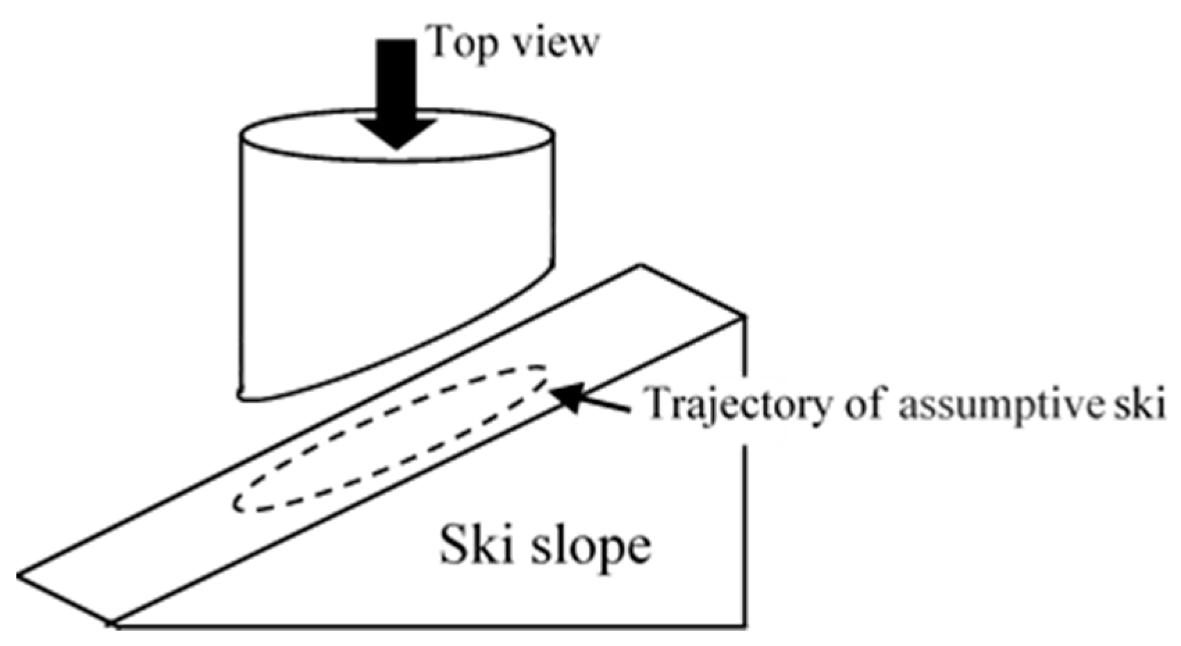
2. Alpine Ski Turning

Alpine ski turns are used by carving turns: turning is done while tilting the upper body to make an angle between the snow surface and the ski. For this reason, the ski has a concave shape called a side curve [18], the ski edge is made to stand on the snow surface to make use of this side curve (the angle formed by the snow surface and the ski at this time is called the edge angle). While maintaining the speed using the centrifugal force generated from the sliding speed, the ski is turned using the arc track generated by the ski. Heretofore, skitting turns have been performed using lateral deviation by turning a leg portion of a straight-shaped ski plate with the outer leg of the turn facing inward. Whereas carving turns performed by alpine skiers, who compete for velocity, can make a sharp turn greater than the arc of the side curve, the skitting turn using the turning motion of the legs has no left or right leg pointing in the same direction. Therefore, the turn is accompanied by lateral deviation, thereby suppressing the speed.
Figure 1 shows a carving turn in an actual competition. Figure 1a shows the first-ranked junior high school girl competitor in Akita Prefecture. Figure 1b shows a fourth-grade elementary school student during the first year of the competition. Assuming that the starting point (yellow mark) is the point at which the lumbar center position changes from the left foot side to the right foot side, the top point is the point at which the ski faces almost rightward below. The finishing point is the point at which the lumbar center position changes from the right foot side to the left foot side. The player depicted in Figure 1a reaches the top point beside the flag gate, whereas the player in Figure 1b reaches the top point after passage through the flag gate. The finish point is delayed because of the effect. It is also readily apparent that the player in Figure 1a turns at an angle between the snow surface and the board while flexing the ski.

3. Passive Turn Type of Ski Robot

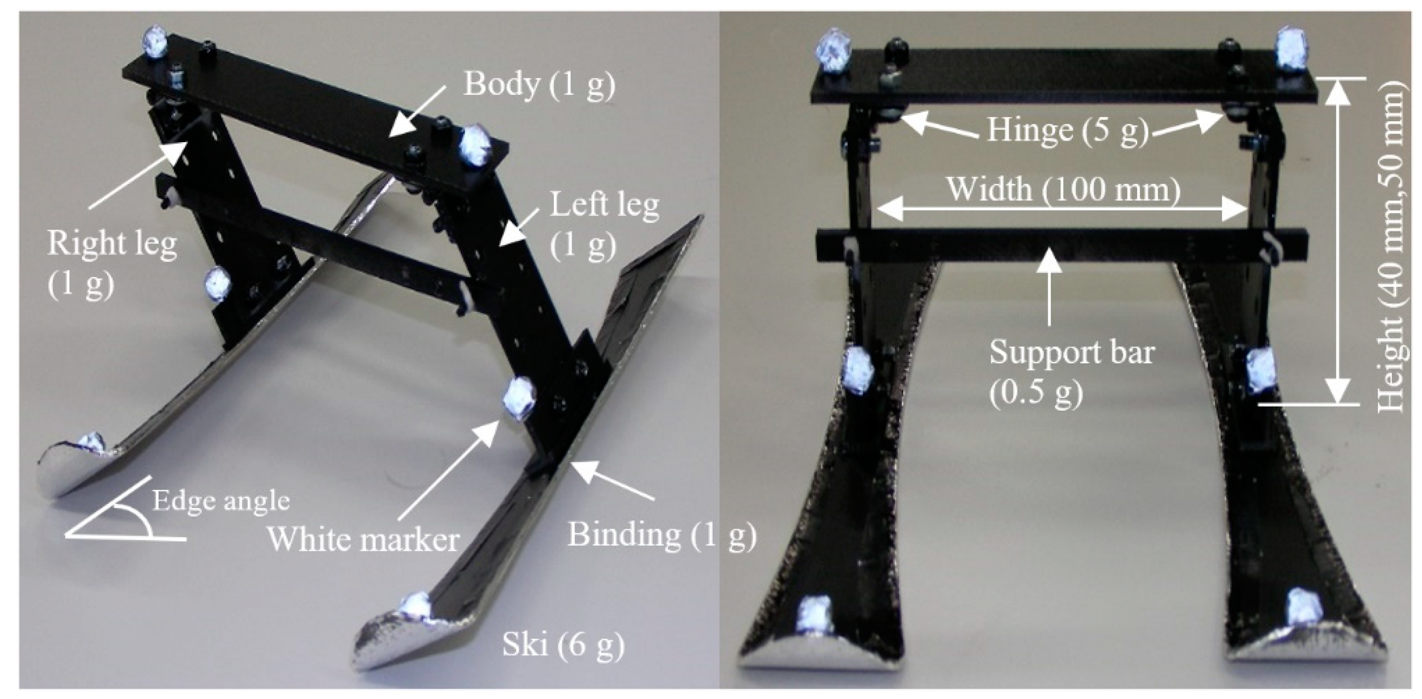
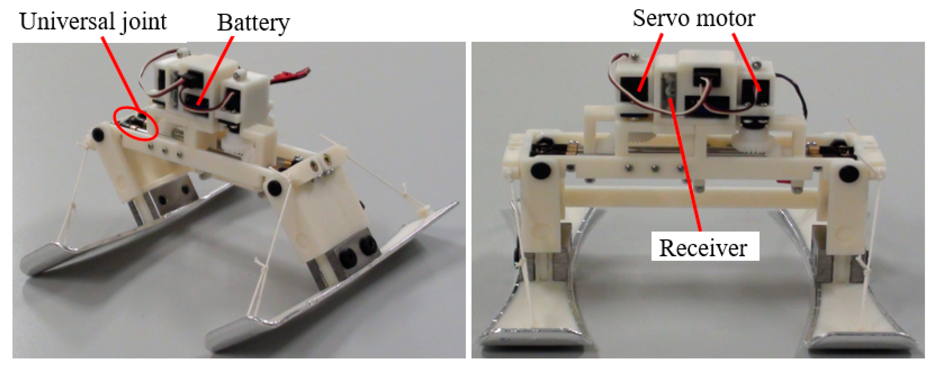
3.1. Composition of Ski Robot

Next, we examine a carving turn. To do so, we produced a passive-turn type of ski robot [19,20] that can use some angle between the snow surface and the skis by shifting its COG. Using it, we can verify experimentally how much of an effect is attributable to ski turning by the ski shape and by the COG position. The passive-turn type of ski robot presented in Figure 2 is made entirely of ABS resin. It weighs 50 g with skis attached. The robot is structured such that its legs and body are connected by hinges, with its left and right legs separated stably using a support bar attached at the body part.
The connections are made using hinges. Therefore, the body part can move freely only in a sideways direction. We set the gap separating the left and right skis using a support bar such that the edge angle can be as great as ±35 deg. A ski is connected firmly to each robot leg so that each leg is always perpendicular to each associated ski surface in its width direction, thereby enabling determination of a ski edge angle. Stainless steel tape was adhered to the lower surfaces of the skis to facilitate sliding. Six white markers are attached to the robot, each at a different location. They are used for motion analyses.

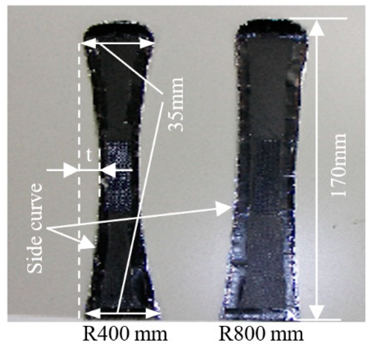
3.2. Profiles of Skis

Figure 3 shows two kinds of skis, each of which is made of ABS resin. They are 1 mm thick, 170 mm long and 35 mm wide at the front end and back end, with respective side curve radii R of 400 mm and 800 mm. Because the ski robot we use for this experiment cannot bend the skis similarly to a real skier, we created and used two pairs of skis, each with a different side curve radius R, by which we were able to assume that the skis were bent.

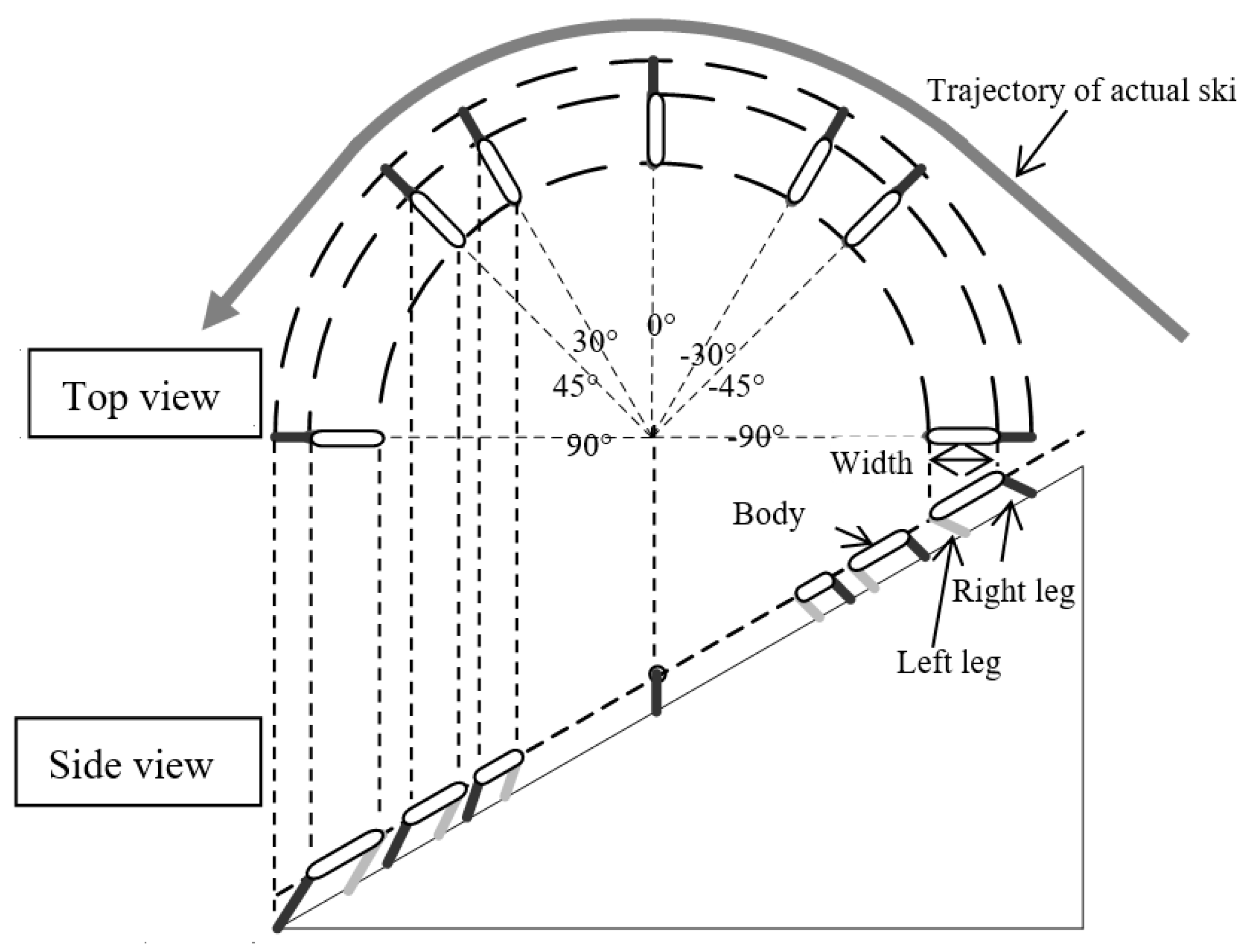
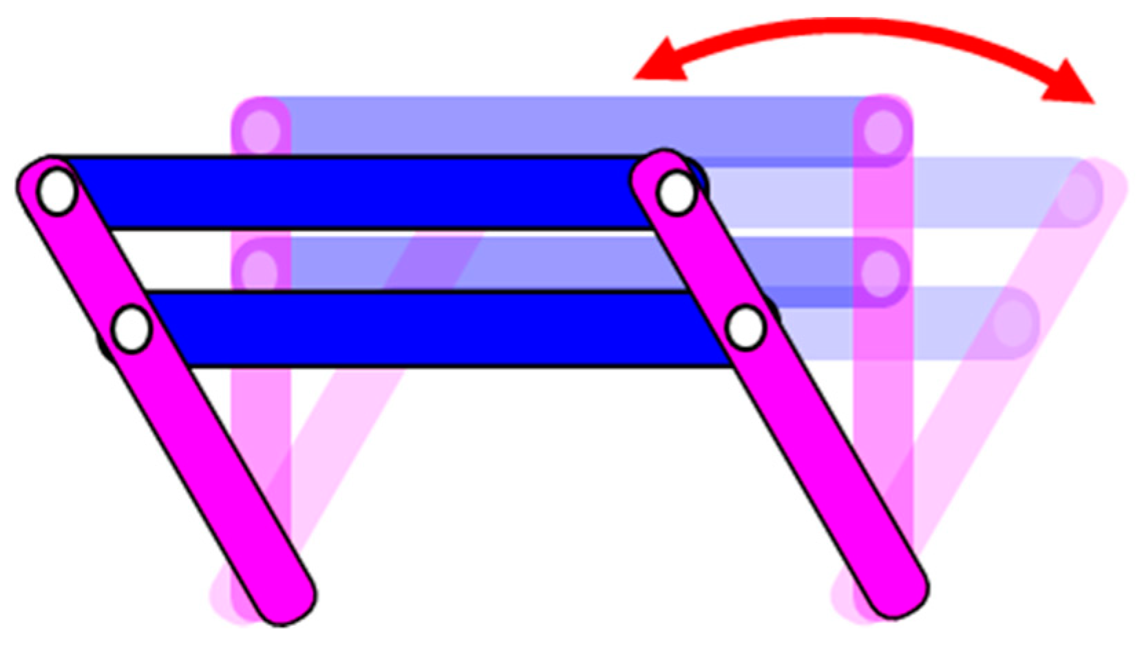
3.3. Passive-Turn Mechanism

To conceptualize the turn mechanism of the ski robot, a ski slope was assumed as portrayed in Figure 4. As viewed from directly above, the locus of a skiing turn locus was assumed as a circle.
Figure 5 was made to show perspectives from directly above a ski slope and directly from the side, devoting attention to the body, a left leg and a right leg. Conditions for depiction were assumed as follows.
  • A 35 deg edge angle was used with a 25 deg ski slope.
  • Side curve radii R of the skis are 400 mm.
  • Speed at the turn is constant.
  • Leg width is 80 mm.
  • Body height is 40 mm.
  • The COG is the body center.
Results show the skiing robot turn motion as the following. Here, the angles in Figure 5 show the ski angle direction as ω. The slope along the Y-axis has ω = 0°. As portrayed in Figure 5, first, the right foot in the upper part of the ski slope changes as a turn progresses to become different at the bottom of the ski slope. At about ω = 30°, the body support changes from the left foot to support by the right foot: the angle of leaning of the body changes. The skiing robot is turning continuously while repeating this motion in alternate directions.

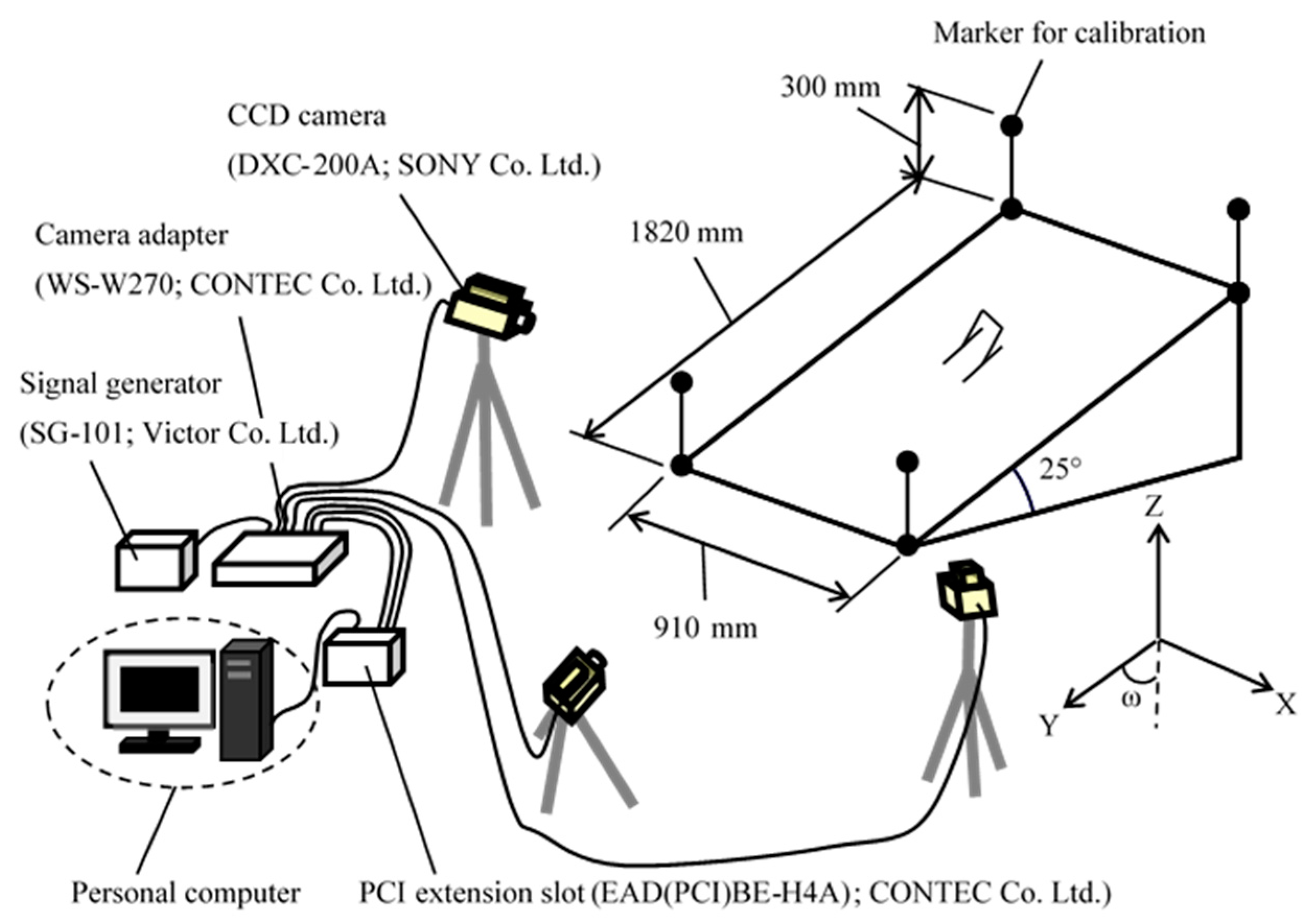
3.4. Experimental Method

For experiment using the passive-turn type of ski robot, we took measurements using three CCD cameras and performed three-dimensional motion analyses. Figure 6 shows the experiment setup. The X-, Y- and Z-axes are also presented in Figure 6. We placed one camera at the front part of the ski slope. The other two were placed respectively at 45 deg left and 45 deg right from the front part. The slope angle was set to 25 deg.
We chose to use a carpet (0.9 m × 1.8 m) as a ski slope, with its fluff height sufficient for the skis to retain contact when a ski edge was angled (fluff height > t in Figure 1). Stainless steel tape was placed on the lower surfaces of the skis to facilitate sliding. Figure 5 shows that the ski angle of direction ω was set.
During the experiments, the ski trajectory, the ski speed and the COG shift timing were observed. The data were verified by making the ski robot turn one direction after another continually while trying to use body heights of 40 mm or 50 mm and its skis with side curve radii R of 400 mm or 800 mm. Initially, the skis were oriented to ω = 0°. The results obtained experimentally using the ski robot were based on averages of five trials.

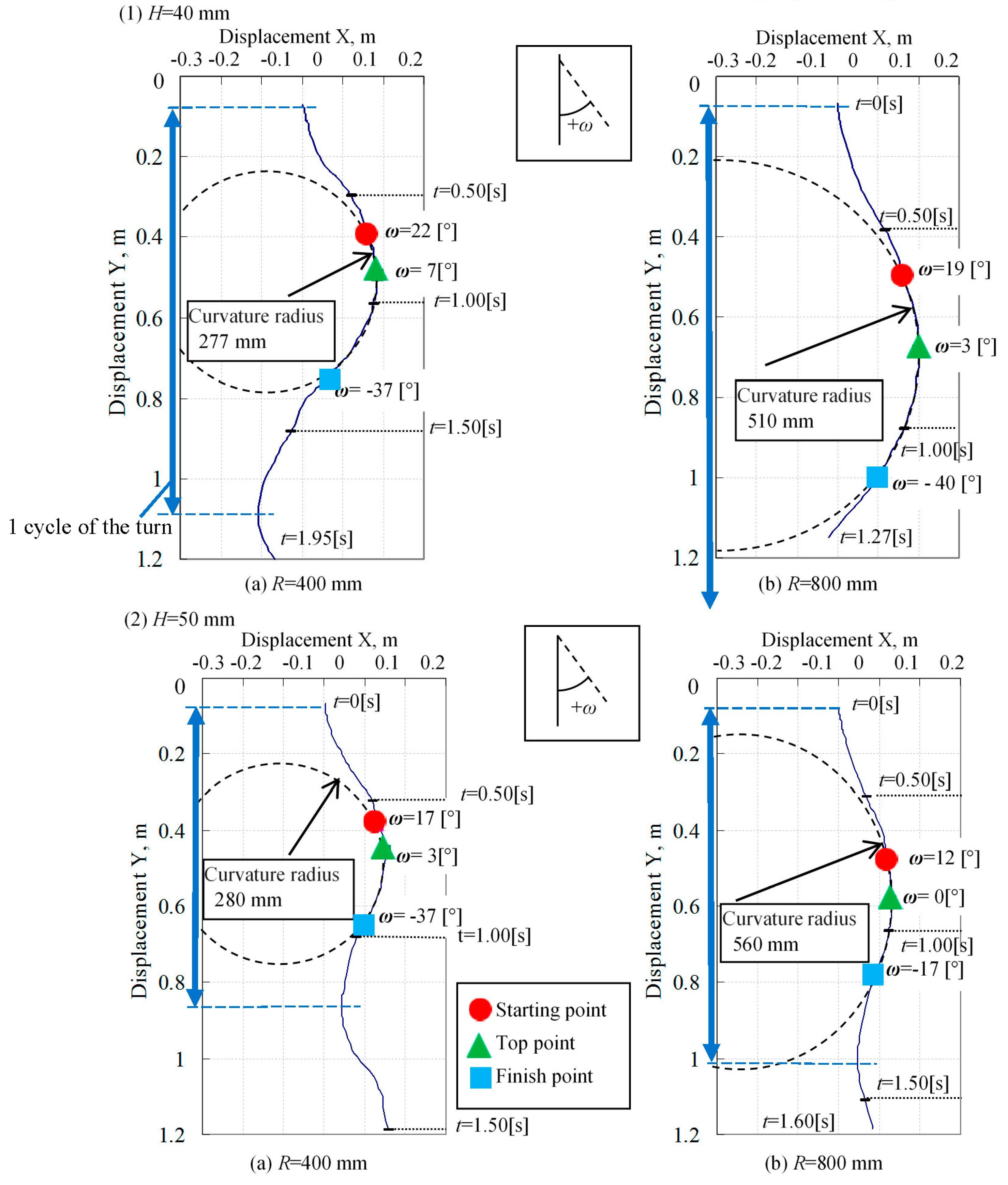
3.5. Body Height Difference Effects on Turning

For these experiments, robots of two types with lumbar heights of 40 mm and 50 mm were slid at an initial velocity of 0 m/s. Then the trajectories of the respective turns were analyzed.
With the start of the left ski running as the origin 0, the X-axis coordinate (positive) is taken in the left direction; the Y-axis coordinate (positive) is taken in the down direction as viewed from the front. The coordinates of the trajectory of the left ski are represented numerically. The results are presented in Figure 7. ω in Figure 7 represents the azimuth angle of the robot: is the angle between the ski orientation and the straight line in the downward slope direction. The radius of the arc formed by connecting the three points of the start point, the top point and the finish point of the turn of the ski robots did not differ significantly. However, results demonstrated that the point at which the robot starts to switch the turn to the opposite side is slower and that the cycle of the turn is larger as the lumbar region is positioned higher. The “cycle of the turn” means the duration of a continuous turn in the left or right direction.

4. Ski Robot Using Variable Height Mechanism of COG

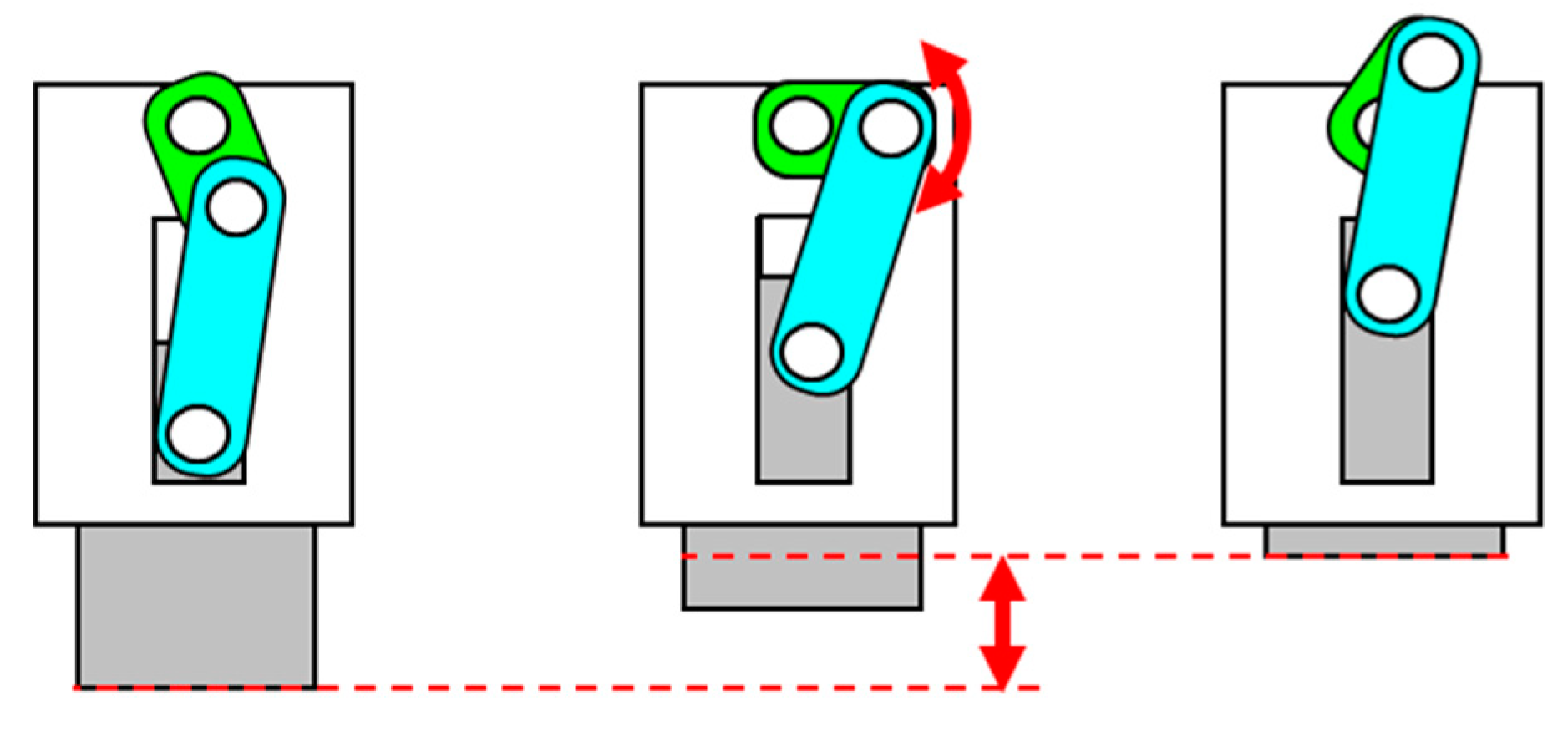
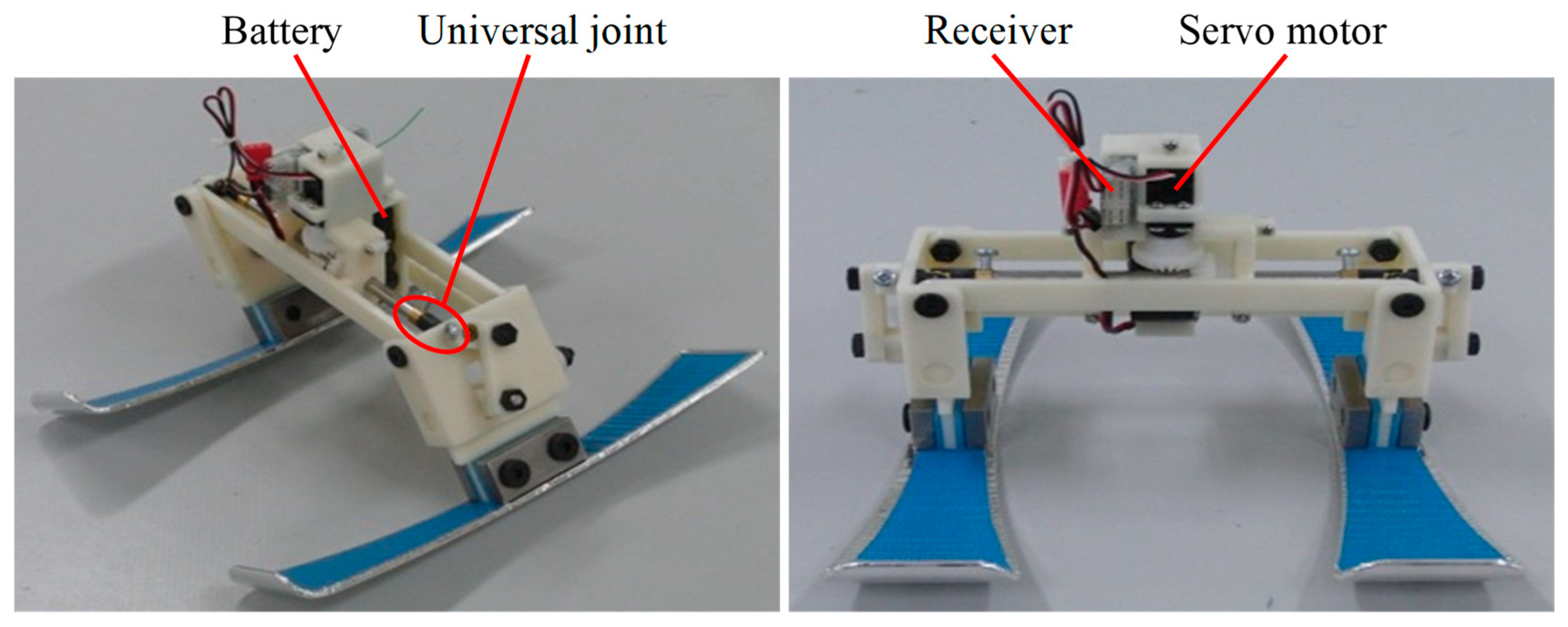
4.1. Composition of Ski Robot Incorporating a Variable Height Mechanism

During sliding of the passive turn type ski robot, the cycle of the turn also differed depending on the leg length difference. Therefore, attention is devoted to the influence of the turn because of the difference in the COG height. Results verified whether the robot ski turn can be controlled by changing the COG height during sliding. For moving the COG to the right and left, which is the basic operation of the ski robot, a passive turn ski robot is applied. We used a four-node link that operates only by gravity, as shown in Figure 8. A mechanism was added to change the leg length to control the robot’s ski turn with the change in the COG height during sliding. This mechanism is a small servomotor (S3156; Futaba Corp., Chiba, Japan). The leg length changes as the two plates of the leg portion slide, as shown in Figure 9. Its operation combines batteries (NR5U50; Futaba Corp.) and transceivers (T6EX, R6004F; Futaba Corp.) to enable wireless radio-controlled radio. A link for moving the COG to the left and right and a mechanism for expanding and contracting the leg are provided. Therefore, a universal joint is used for the rotation axis of the mechanism to expand and contract the leg.
Figure 10 shows a ski robot with an additional variable COG height mechanism. The robot leg length was a minimum of 50 mm; the length of extension of the legs was a maximum of 15 mm. The width of both legs was 110 mm. The side curve radius of the ski was 400 mm. The edge angle range was −35° to 35°. The total weight was 263 g.

4.2. Servomotor Response Characteristics

Servomotors and transmitters/receivers are used as robot mechanisms. The legs are extended and contracted by operation of the radio controller. Therefore, a delay occurs between the transmitter operation and the servomotor operation. To assess this delay, the respective operations of the transmitter and the servomotor were photographed using a high-speed camera (420 fps) using the S3156 servomotor and the T6EX and R6004F transceivers used for the robot. Then the reaction time of the servomotor was measured from the video. Dartfish software (Dartfish Japan Co., Ltd.) was used for the measurement. Results confirmed that a lag of about 0.06 s occurred between the transmitter and servomotor operations.

4.3. Switching Time in the COG Height

When the robot changes the COG height, it takes some time from the operation of the servomotor until the COG height changes. Therefore, change time for the case where the leg length was increased from 50 mm to 65 mm and for the case where the leg length was decreased from 65 mm to 50 mm ware examined. Similar to the servomotor response characteristics, the state of the change in the COG was photographed using a high-speed camera (420 fps); it was also measured using Dartfish software. Measurement results confirmed that about 0.29 s was necessary for the leg length to change from 50 mm to 65 mm; about 0.21 s was necessary for the leg length to change from 65 mm to 50 mm.

4.4. Experimental Method

Measurement fields such as the measurement range and the slope angle are the same as those shown in Figure 6. As an experiment method, the position at which the distance from the origin in the Y-axis direction is 1500 mm distance is marked. This mark is used as a point for changing the COG height of the robot. We assessed sliding at an initial velocity of 0 m/s from the leg lengths of 65 mm and 50 mm and change of the leg length as it passes by the point. The legs were operated to have lengths of 65 mm to 50 mm and 50 mm to 65 mm, respectively. The cycle of the turn was compared in cases where the COG height was not operated. The results obtained experimentally using the ski robot were based on averages of five trials.

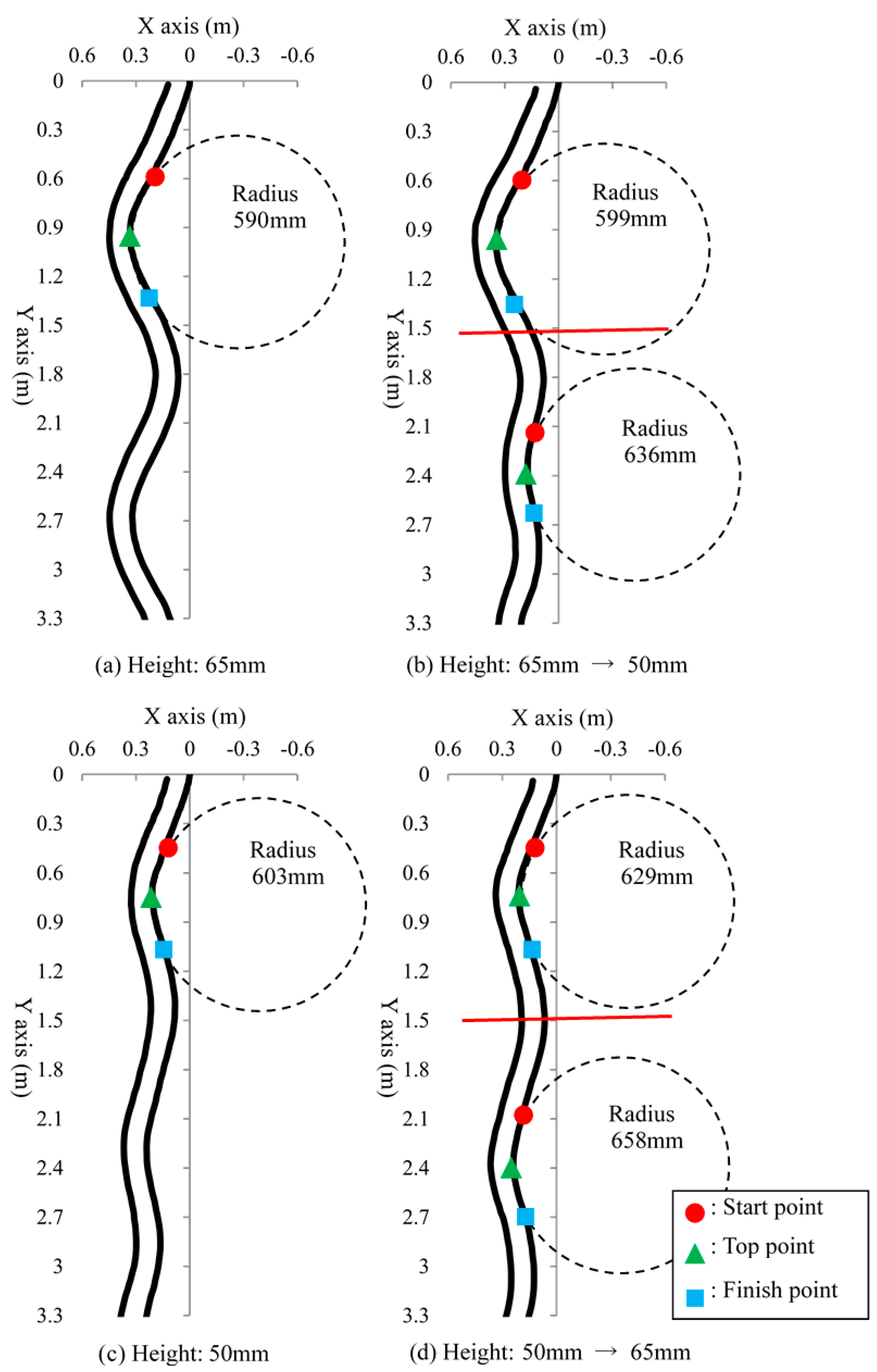
4.5. Experimental Results

Figure 11 shows the trajectory of both skis during the turn. The red lines in Figure 11b,d respectively show the points at which the COG changes. Results show that the trajectory of the turn thereafter also changes when the COG position is lowered from a high state to a low state. Moreover, the cycle of the turn is more reduced than in the case in which the COG height is not changed. In the case in which the position of the COG is raised from the low state to the high state, similarly, the subsequent trajectory changes; the cycle of the turn increases.
However, no significant difference was found in the radius of curvature of the turns before and after the change in the COG in either case. The experimentally obtained results confirmed that the switching point of the turn, which is the movement of the COG in the left and right direction, was changed by changing the timing of raising and lowering the COG height.

5. Ski Robot Using Variable Edge Angle Mechanism

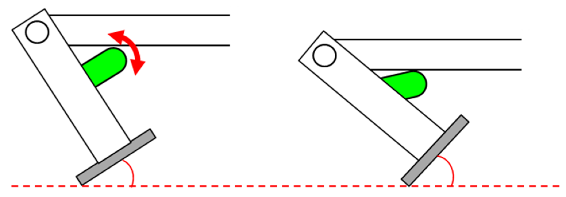
5.1. Composition of Ski Robot Using Variable Edge Angle Mechanism

In actual skiing, there is a difference in the position of the senior and the lower in turning. One of them is the difference in edge angle and the senior person performs the turn while making the edge large at the time of the turn. Therefore, attention is paid to the influence of the turn due to the difference in the edge angle and it is verified whether or not the ski turn of the robot can be controlled by changing the edge angle during the sliding.
For moving the center of gravity to the left and right, which is the basic operation of the ski robot, a four-node link capable of operating only by gravity is used, as in a passive turn type ski robot having a center of gravity variable mechanism. In addition, a mechanism that can change the edge angle has been added to control the robot’s ski pattern by changing the edge angle during sliding. In this mechanism, a small servomotor (S3156; Futaba Electronics Industry) is installed on both leg portions and the edge angle is changed by rotating a small rod supporting the lumbar up and down as shown in Figure 12. Also, batteries (NR-4QC; Futaba Electronics) and transceivers (T6EX, R6004F; Futaba Electronics) can be combined to enable wireless-controlled operation.
The servomotors of both leg portions are connected to the two-forked cord. Therefore, they are mutually interlocked to perform the same degree of angulation on the left and right sides. Figure 13 shows a ski robot with an added edge angle variation mechanism. The edge angle can be varied from ±30° to ±35°. The robot leg length was 55 mm. The width of both legs was 110 mm. The side curve radius of the ski was 400 mm. Its total weight was 238 g.

5.2. Switching Time in the Edge Angle

When the robot changes the edge angle, it takes some time from the operation of the servomotor until the edge angle changes. Therefore, the change times in the cases of increasing the edge angle 30° to 35° and of decreasing the edge angle from 35° to 30° were examined. The edge angle change was photographed using a high-speed camera (420 fps) and was measured using Dartfish software. Results confirmed that 0.14 s was necessary for the edge angle to change from 30° to 35°; about 0.16 s was necessary for the edge angle to change from 35° to 30°.

5.3. Experimental Method

Experiments were conducted to determine whether the cycle of the turn could be controlled by changing the edge angle during the sliding. The measurement fields such as the measurement range and the angle of the slope are the same as those shown in Figure 6.
As an experimental method, the position at which the distance from the origin in the Y-axis direction is the 1500 mm distance is marked. This mark is used as a point at which the edge angle of the robot is changed. The edge angles were operated to be 35° to 30° and 30° to 35°, respectively and the cycles of the turns were compared with those in the case where the edge angles were not operated.

5.4. Experimental Results

Figure 14 shows the trajectories of both skis during the turn. The red lines in Figure 14b,d represent points that change the edge angle. In Figure 14c,d, the “start, top and finish point” markers move from left side because the turn cycle is shorter than those shown in Figure 14a,b. The turn posture at 1500 mm of the switching point is not the same. When the edge angle is reduced from 35 deg to 30 deg, the trajectories of the subsequent turns are also changed. Results demonstrate that the radius of curvature of the turns is greater than in the case in which the edge angle is not changed. Similarly, when the edge angle is increased from 30° to 35°, the subsequent trajectory changes. The radius of curvature of the turn decreases. The experimentally obtained results confirmed that the magnitude of the curve of the turn was altered by changing, increasing or decreasing, the edge angle. The experimentally obtained results for the ski robot were based on the averages of five trials.

6. Ski Robot Using Variable Mechanism of Ski Flexure

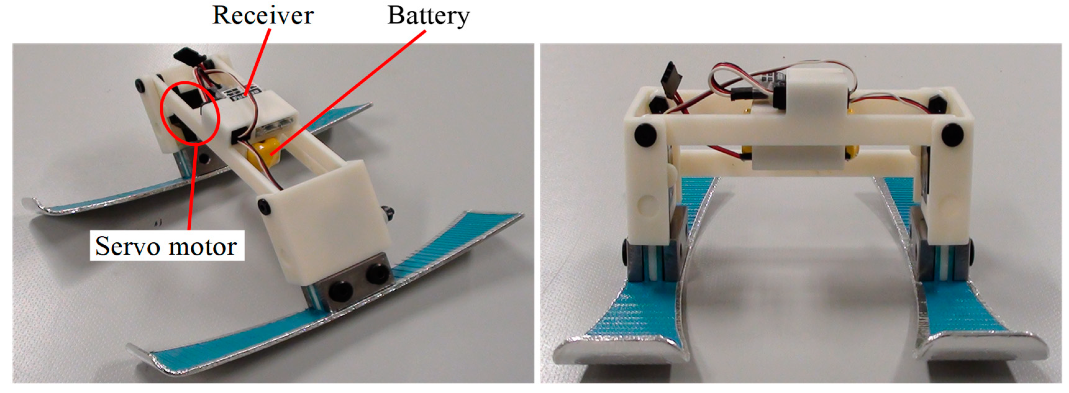
6.1. Ski Robot Incorporating a Mechanism of Variable Ski Flexure

For turns during skiing, the ski deflection is a major factor affecting motion. If the ski itself is straight and does not flex, then it cannot be turned well by raising the edge. The skier intentionally loads the ski plate surface when turning and turns while flexing the ski to create a curved surface. Therefore, attention must be devoted to the influence of the turn because of the presence or absence of ski deflection. Results verified whether the ski turn of the robot can be controlled by deflecting the ski during sliding. The ski has a side curve. Therefore, it is possible to turn the ski even in a state in which the ski is not bent.
For moving the COG to the left and right, which is the basic operation of the ski robot, a four-node link capable of operating solely by gravity is used as in a passive turn type ski robot with a variable mechanism of the COG (edge angle). In addition, a mechanism has been added to flex the plate to control the robot’s ski turn by flexing the plate during sliding. This mechanism is powered by two small servomotors (S3156; Futaba Corp.). The ski can be flexed by simultaneously rotating the two plates and pulling both ends of the ski up with yarn, as portrayed in Figure 15. Its operation combines batteries (NR5U50; Futaba Corp.) and transceivers (T6EX, R6004F; Futaba Corp.) to enable wireless radio-controlled radio. The two servomotors are interlocked because they are connected to the two-forked cord. A link for moving the COG to the left and right and a mechanism for deflecting the ski are provided. Therefore, a universal joint is used for the rotation axis of the mechanism for deflecting the ski.
Figure 16 shows a ski robot with an additional variable ski deflection mechanism. The ski changes from a flat state to a deflected state. The robot leg length was 55 mm. The width of both legs was 110 mm. The side curve radius of the ski was 400 mm. The edge angle range was −35° to 35°. The total weight was 318 g.

6.2. Switching Time in the Ski Flexure

When the robot deflects the ski, it takes some time after the servomotor operates until the plate deflects. Therefore, the change time in the case where the ski was bent from the flat state and in the case where it was returned from the bent state to the flat state was examined. The ski changes are photographed with a high-speed camera (420 fps) and measured by Dartfish software. From the measurement results, it can be confirmed that about 0.13 s is required for the ski to deflect from the flat state and about 0.10 s is required for the ski to return from the bent state to the flat state.

6.3. Experimental Method

Experiments were conducted to ascertain whether the cycle of turn can be controlled by varying the ski deflection during sliding. Measurement fields such as the measurement range and the slope angle are the same as those shown in Figure 6.
With the start of sliding of the left ski as the origin 0, the X-axis coordinate (positive) is taken in the left direction, the Y-axis coordinate (positive) is taken in the down direction as viewed from the front and the coordinates of the trajectories of the left ski and the right ski are represented numerically. As an experiment method, the position at which the distance from the origin in the Y-axis direction is the 1500 mm distance is marked. This mark is used as a point for changing the deflection of the ski of the robot. Sliding of the ski from flexed and flat at an initial velocity of 0 m/s is done to change the ski deflection as it passes by the point. The ski was manipulated from a deflected state to a flat state and from a flat state to a deflected state, respectively. The cycle of the turn was compared with the case in which the plate deflection was not manipulated. The results obtained experimentally using the ski robot were based on averages of five trials.

6.4. Experimental Results

Figure 17 shows the trajectory of both skis during the turn as the ski robot slid. The red lines in Figure 17b,d show points that change the deflection of the ski plate. When the ski is made to slide while bent, the radius of curvature of the turn is smaller. Also, the turn is deeper than when the ski is made to slide in a flat state. For the turn in which the ski plate deflection was changed in the middle of the sliding, although the curvature radius after the change could not be calculated because the number of turns within the measurement range was small, the change of the turn trajectory in both cases can be confirmed. Experiment results suggest that a turn with a flexed ski can be done with a smaller radius of curvature and that the subsequent trajectory can also be changed by changing the flexion of the ski during sliding. Therefore, the curvature of the turn can be changed by deflecting the plate during turning.

7. Conclusions

For this study, a passive turn ski robot was developed to improve the competitive ability of alpine skiers. Subsequently, experiments were conducted to ascertain whether mechanisms for varying the COG height, edge angle and ski deflection could be added to the passive turn type ski robot to control turns solely by these changes. The results of the respective investigations are summarized below.
  • A simple passive-turn type ski robot was fabricated to assess effects of differences of the robot construction and COG height on turning. The use of a hinge to connect the lumbar and leg allows the robot to repeat adduction and abductor movements of the hip joint using gravity exerted during sliding and to turning the hip joints continuously. In addition, when comparing the sliding trajectories of robots having different COG heights, the higher the COG is, the later the timing of switching to the opposite side turn becomes. For that reason, the cycle of the turn becomes larger.
  • To clarify the importance of the timing of changing the COG height in the turn by noting the influence on the turn caused by the COG height difference, a mechanism for varying the COG height was added to the passive turn ski robot. For turns in which the COG height was manipulated during running, the radius of curvature was almost identical. Only the cycle of the turn changed. Results show that the timing of raising and lowering the COG height changed the switching point of the turn, which is the movement of the COG in the left and right directions.
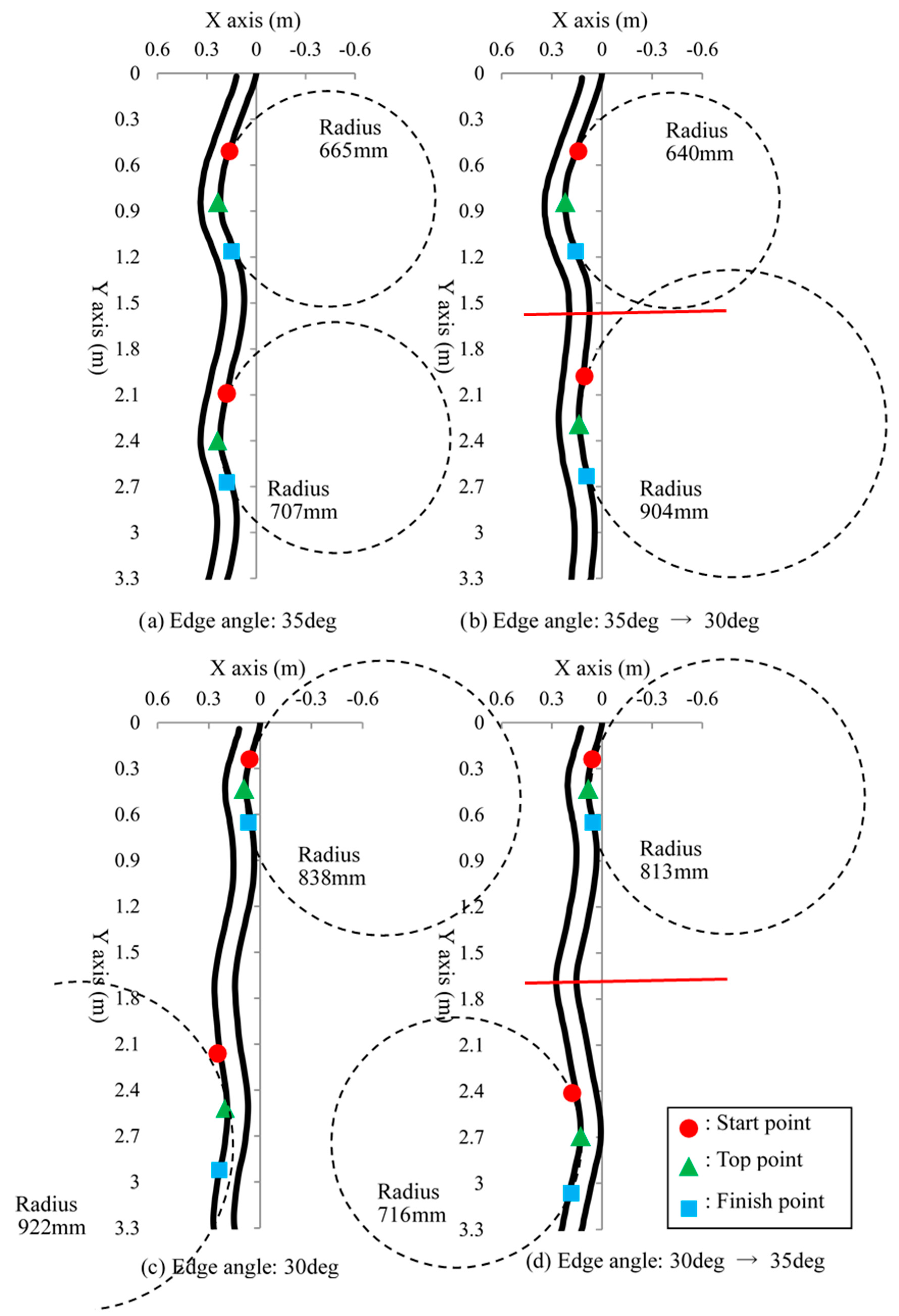
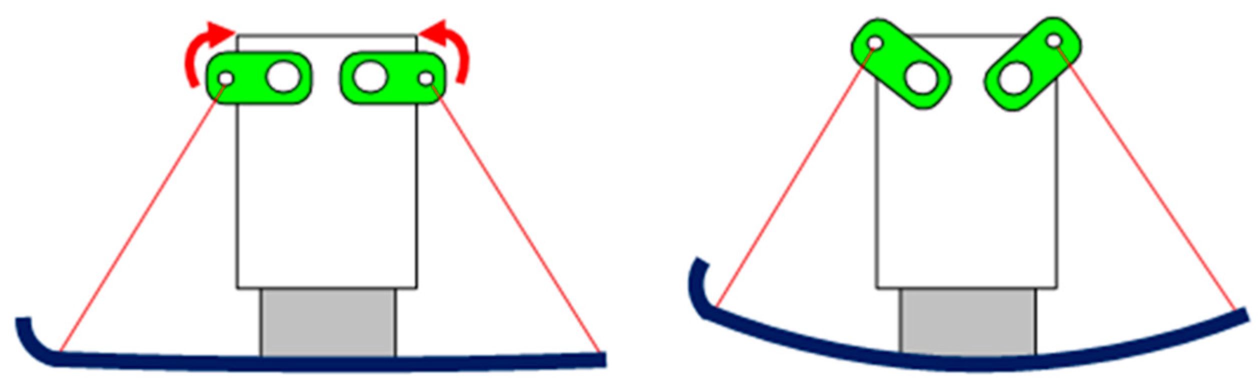
  • To clarify the importance of the edge angle in the turn by noting the influence on the turn by the difference in the edge angle, which is one factor affecting the turn, a mechanism for varying the edge angle was added to the passive turn type ski robot. Results show that the radius of curvature of the turn was changed during turning in which the edge angle was manipulated during sliding. Moreover, the depth of the arc of the turn was altered by the timing of the edge angle increase or decrease.
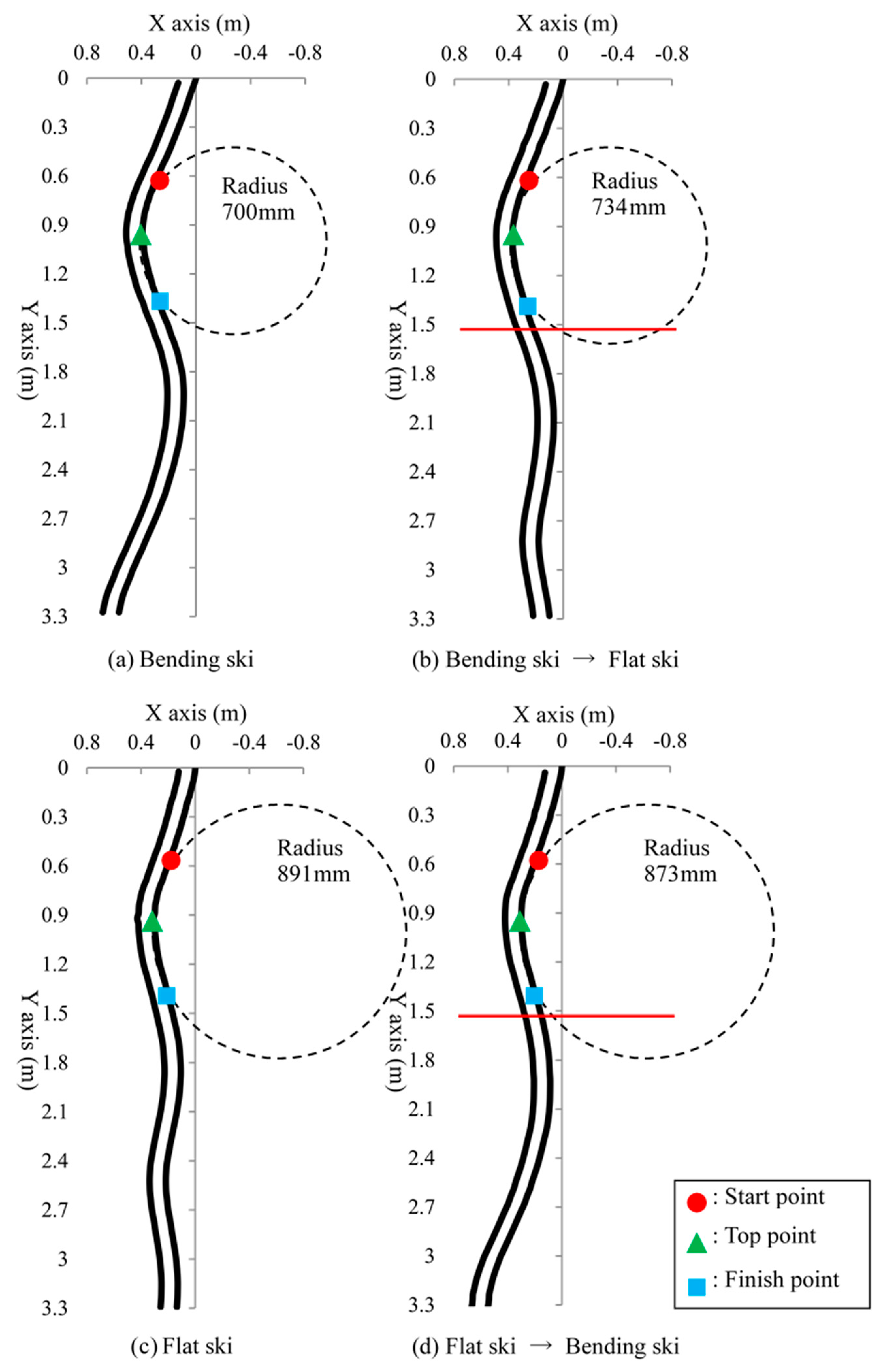
  • A mechanism for varying the ski deflection was added to the passive turn ski robot to clarify the importance of the ski deflection during turning by elucidating the influence on turning of the ski deflection the skier exerts during turning. Results demonstrated that the turn can be performed with a small curvature by deflecting the ski and show that the turn trajectory was altered by the plate deflection during sliding.
  • No consideration of friction exists in this study. Therefore, we would like to defer to future work our planned comparison of the running experiment results and a theoretical model incorporating the contact area of the snow in an alpine ski model.

Author Contributions

T.S. wrote the paper, performed the experiments and analyzed the data; N.S. conceived the method and helped to modify the paper. All authors have read and approved the final manuscript.

Funding

This research received no external funding.

Acknowledgments

The authors would like to thank K. Kono for technical assistance with the experiments.

Conflicts of Interest

The authors declare no conflict of interest.

References

  1. Hosokawa, K.; Kawai, S.; Sakata, T. Improvement of damping property of skis. Sports Eng. 2002, 5, 107–112. [Google Scholar] [CrossRef]
  2. Khmelev, V.N.; Levin, S.V.; Tsyganok, S.N.; Shalunov, A.V.; Chipurin, E.V. The New Technology of Sliding Ski Surface Covering. In Proceedings of the 6th Annual 2005 International Siberian Workshop and Tutorials on Electron Devices and Materials, Erlagol, Altai, Russian Federation, 1–5 July 2005; pp. 86–89. [Google Scholar]
  3. Shimizu, S.; Hasegawa, K.; Nagasawa, T. Alpine skiing robot. Adv. Robot. 1992, 6, 375–376. [Google Scholar] [CrossRef]
  4. Kawai, S.; Otani, H.; Sakata, T. Coupled Motion of Ski and Elastic Foundation Under Ski Control. JSME Int. J. Ser. C 2003, 46, 614–621. [Google Scholar] [CrossRef] [Green Version]
  5. Sakata, T.; Tsukiyama, M. Effects of Position of Shoe Center on Ski Turn. JSME Int. J. Ser. C 1999, 42, 922–929. [Google Scholar] [CrossRef]
  6. Tada, N.; Hirano, Y. In Search of the Mechanics of a Turning Alpine Ski Using Snow Cutting Force Measurements. Sports Eng. 2002, 5, 15–22. [Google Scholar] [CrossRef]
  7. Sahashi, T.; Ichino, S. Coefficient of Kinetic Friction of Snow Skis during Turning Descents. Jpn. J. Appl. Phys. 1998, 37, 720–727. [Google Scholar] [CrossRef]
  8. Morawski, J.M. Control System Approach to a Ski-turn Analysis. J. Biomech. 1973, 6, 267–279. [Google Scholar] [CrossRef]
  9. Sakata, T.; Ito, T. Simulation of Ski Turn. In Proceedings of the 2nd International Conference the Engineering of Sports, Sheffield, UK, 8 July 1998; pp. 361–368. [Google Scholar]
  10. Kagawa, H.; Yoneyama, T.; Okamoto, A.; Komatsu, H. Development of a Measuring System for Joint Angles of a Skier and Applied Forces during Skiing. JSME Int. J. Ser. C 1998, 41, 214–219. [Google Scholar] [CrossRef]
  11. Kawai, S.; Yamaguchi, K.; Sakata, T. Ski Control Model for Parallel Turn Using Multibody System. JSME Int. J. Ser. C 2004, 47, 1095–1100. [Google Scholar] [CrossRef] [Green Version]
  12. Hasegawa, K.; Shimizu, S. Dynamics of Repeated Parallel Turns of Snow Ski. J. Jpn. Soc. Sports Ind. 1995, 5, 9–18. (In Japanese) [Google Scholar] [CrossRef] [Green Version]
  13. Sahashi, T.; Ichino, S. Carving-turn and edging angle of skis. Sports Eng. 2001, 4, 135–145. [Google Scholar] [CrossRef]
  14. Nemec, B.; Lahajnar, L. Control and Navigation of the Skiing Robot. In Proceedings of the 2009 IEEE/RSJ International Conference on Intelligent Robots and Systems, St. Louis, MO, USA, 10–15 October 2009; pp. 2321–2326. [Google Scholar]
  15. Yoneyama, T.; Kagawa, H.; Unemoto, M.; Iizuka, T.; Scott, N.W. A ski robot system for qualitative modeling of the carved turn. Sports Eng. 2009, 11, 131–141. [Google Scholar] [CrossRef]
  16. Shimizu, S.; Doki, H.; Nojiri, N. Robot Models for Passive Dynamic Skiing—A Skidding-turn Model of Abduction and Adduction with Inner Rotation of the Hip Joints. J. Ski Sci. 2012, 9, 29–33. (In Japanese) [Google Scholar]
  17. Shimizu, S.; Doki, H.; Yamane, M.; Nojiri, N. Robot Models for Passive Dynamic Skiing—A Snowplow Model of Rotation Involving the Hip Joints around the Femur Axes. J. Ski Sci. 2013, 10, 13–18. (In Japanese) [Google Scholar]
  18. Shimizu, S.; Doki, H.; Yamane, M.; Sakatani, M.; Nojiri, N. Robot Models for Passive Dynamic Skiing—A Skidding-turn Model of Inward Lean with Inner Rotation of the Hip Joints. J. Ski Sci. 2014, 11, 13–18. (In Japanese) [Google Scholar]
  19. Kono, K.; Saga, N. Experimental Study on Alpine Skiing Turn Using Passive Skiing Robot. In Intelligent Robotics and Applications; Lecture Notes in Artificial Intelligence; Springer: Berlin/Heidelberg, Germany, 2009; Volume 5928, pp. 1044–1050. [Google Scholar]
  20. Kono, K.; Saga, N. Development of a passive turn type skiing robot with variable height mechanism of gravitational center. J. Robot. Mechatron. 2012, 24, 372–378. [Google Scholar] [CrossRef]
Figure 1. Turn used in alpine skiing.
Applsci 08 02643 g001
Figure 2. Structure of passive turn type ski robot (50 g).
Applsci 08 02643 g002
Figure 3. Ski design.
Applsci 08 02643 g003
Figure 4. Simple assumption of the skiing robot turn.
Applsci 08 02643 g004
Figure 5. Simple assumption of turn of the skiing robot.
Applsci 08 02643 g005
Figure 6. Experimental setup.
Applsci 08 02643 g006
Figure 7. Experimental results related to the difference of the body height.
Applsci 08 02643 g007
Figure 8. Rectangular linkage for center of gravity shift.
Applsci 08 02643 g008
Figure 9. Variable height mechanism of the foot length.
Applsci 08 02643 g009
Figure 10. Ski robot with variable height mechanism.
Applsci 08 02643 g010
Figure 11. Trajectories of ski robot with variable gravitational center height mechanism.
Applsci 08 02643 g011
Figure 12. Variable mechanism of the edge angle.
Applsci 08 02643 g012
Figure 13. Ski robot with variable mechanism of the edge angle.
Applsci 08 02643 g013
Figure 14. Trajectories of ski robot with variable edge angle mechanism.
Applsci 08 02643 g014
Figure 15. Variable mechanism of the ski flexure.
Applsci 08 02643 g015
Figure 16. Variable mechanism of the ski flexure.
Applsci 08 02643 g016
Figure 17. Trajectories of ski robot with variable ski flexure mechanism.
Applsci 08 02643 g017

