Long-Term Behaviour of Precast Concrete Deck Using Longitudinal Prestressed Tendons in Composite I-Girder Bridges

Abstract
:1. Introduction
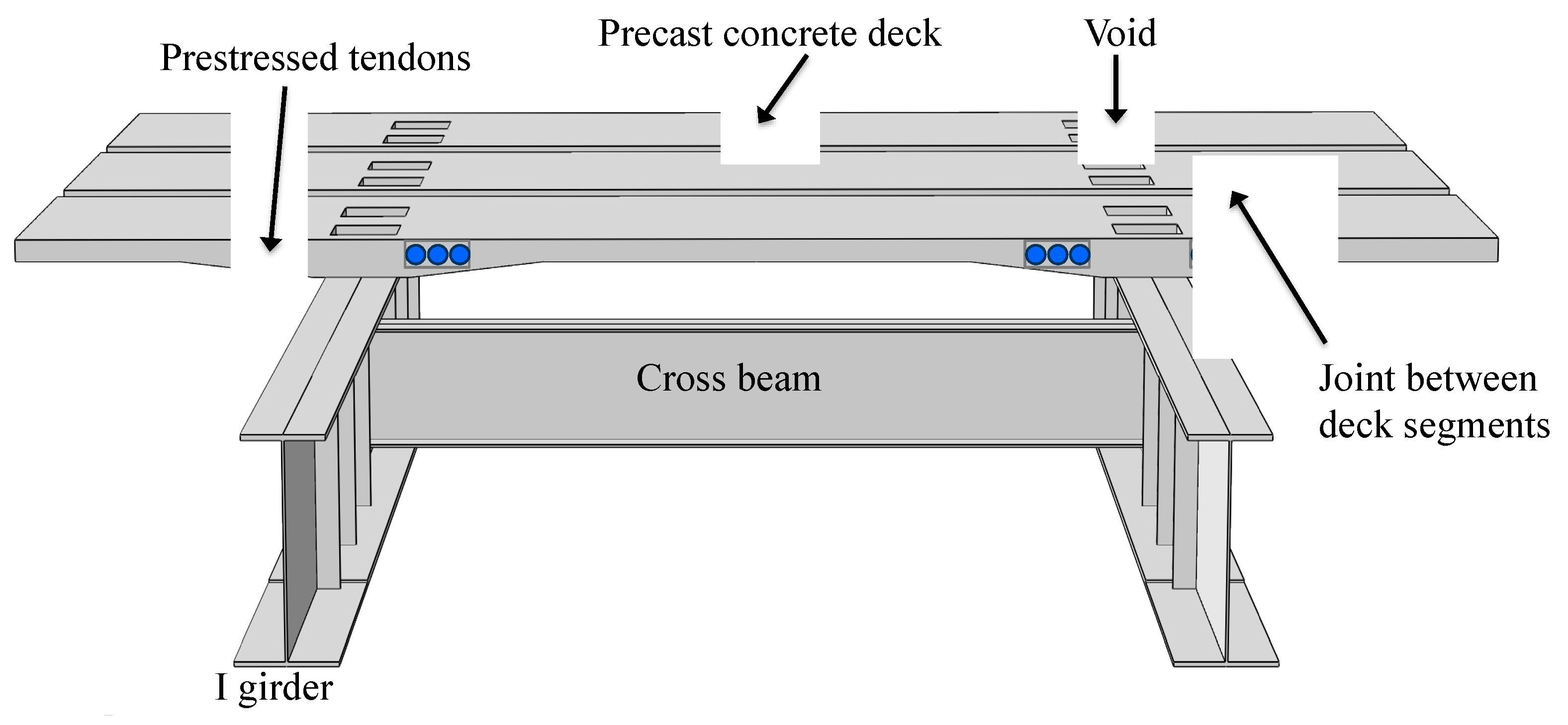
2. Case of a Twin-I Girder Composite with Precast Deck
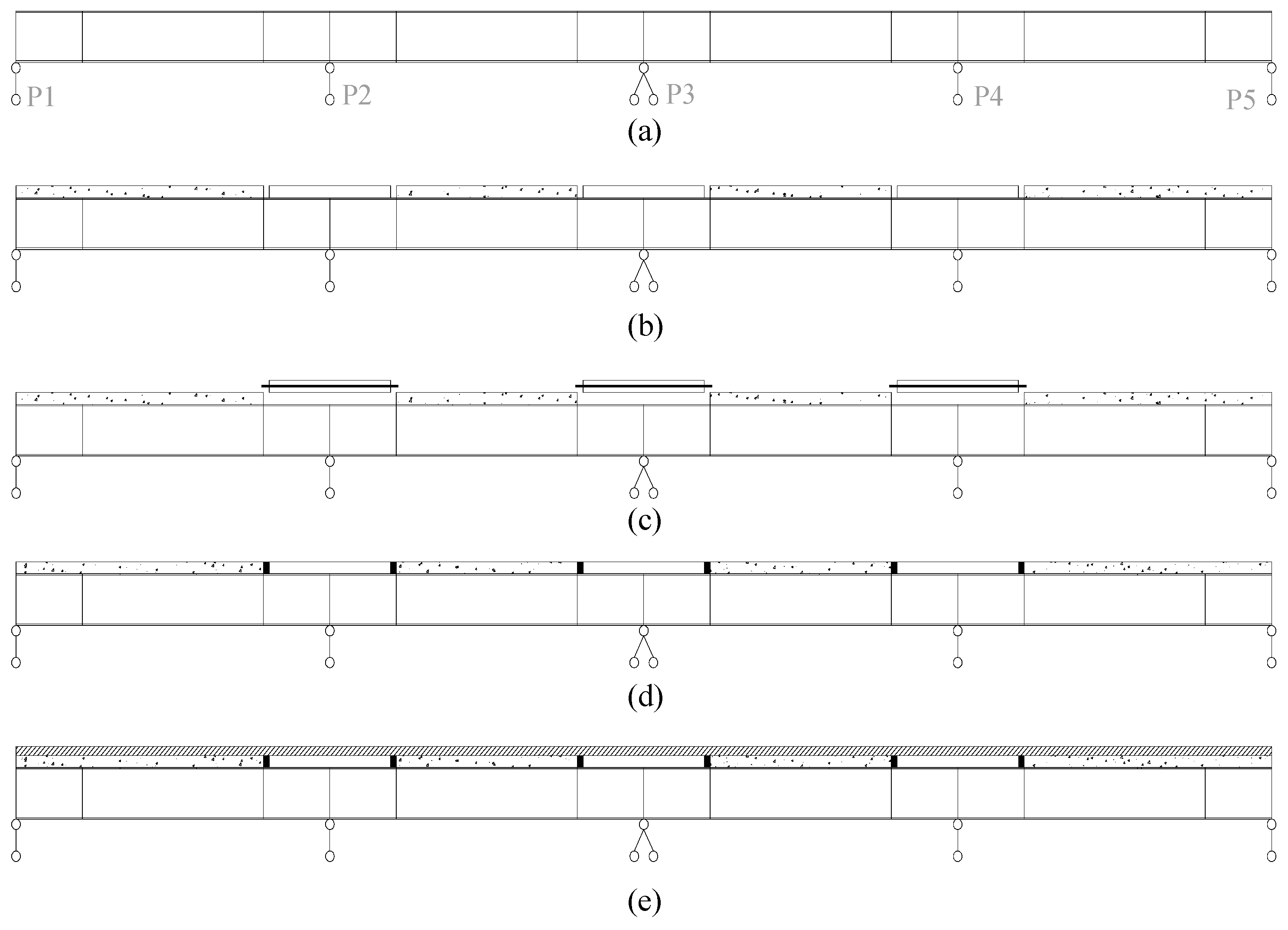
- (1)
- The steel girders are lifted and connected to be a four-span continuous system.
- (2)
- All the precast concrete segments are lifted to the steel girders and the concrete deck and the steel girders are not composite (the concrete in the voids are not casted).
- (3)
- Only the precast concrete deck segments within the hogging regions (e.g., within the regions at interior supports) are prestressed and the steel girders are not composite with the concrete deck at this time.
- (4)
- The joints and voids are casted with concrete to make the concrete deck composite with the steel girders.
- (5)
- The transverse tendons are prestressed and the bridge is constructed with the wearing surface and the attached appurtenances (barriers, railings, lights, etc.).
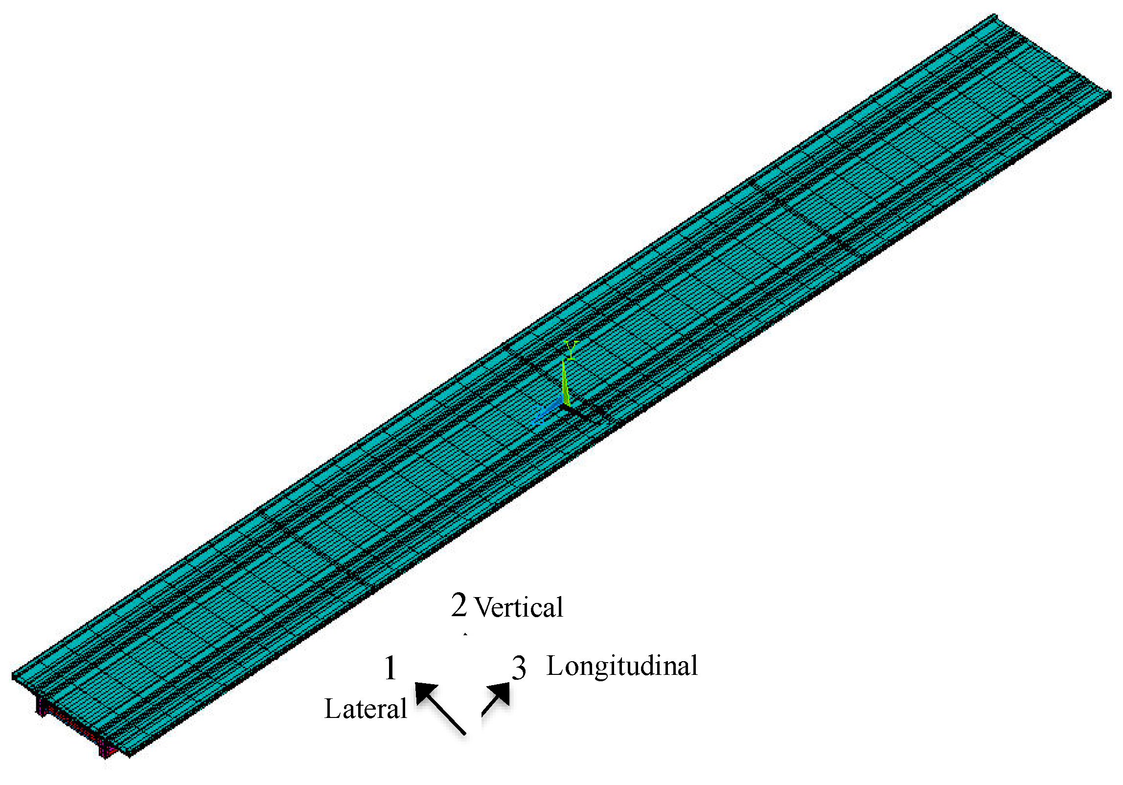
3. Finite Element Model
3.1. Elements and Meshes
3.2. Material Models
3.3. Boundary Conditions
4. Long-Term Behaviour Analysis
4.1. Prestressed Concrete Deck Condition
4.2. Constructed Condition
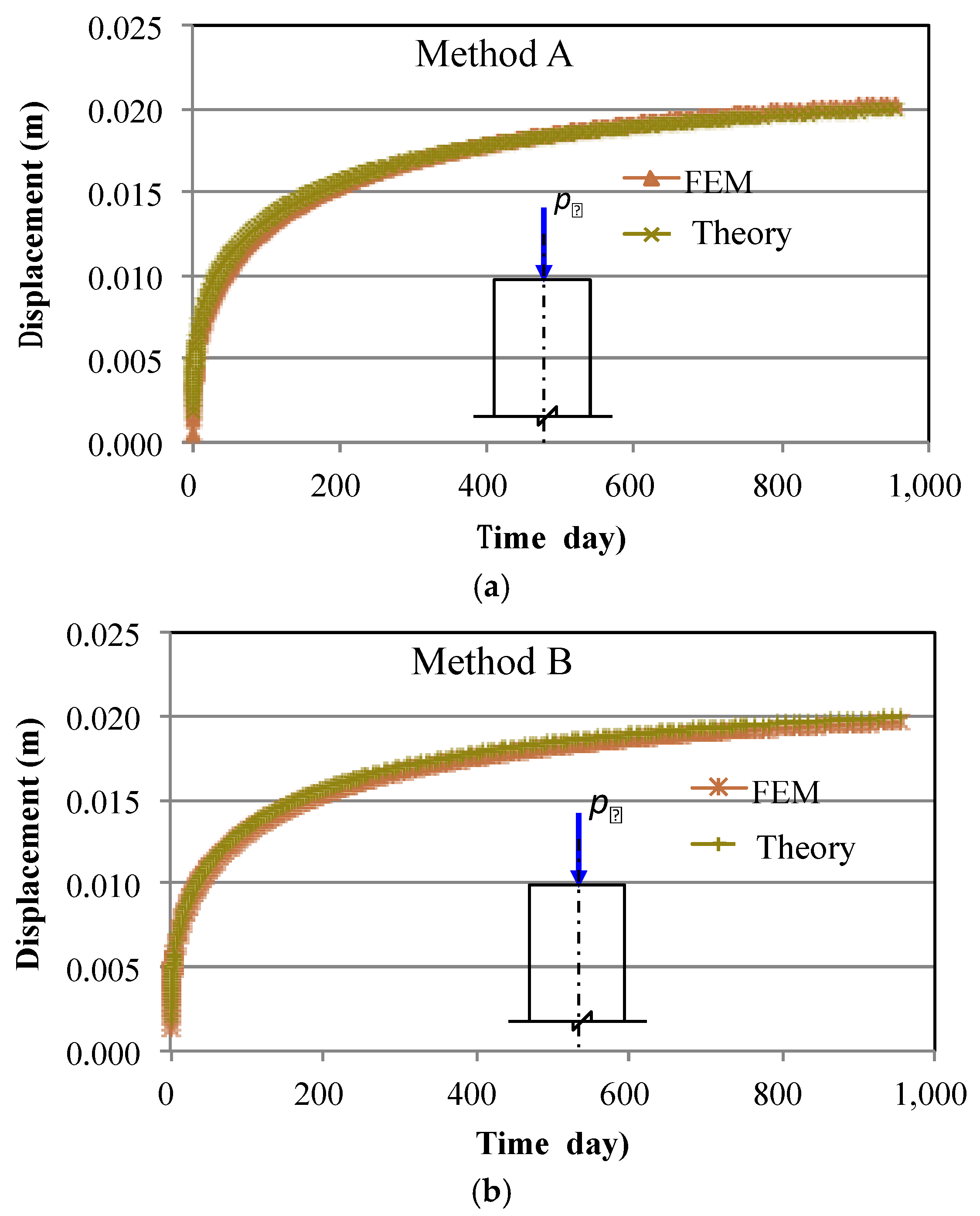
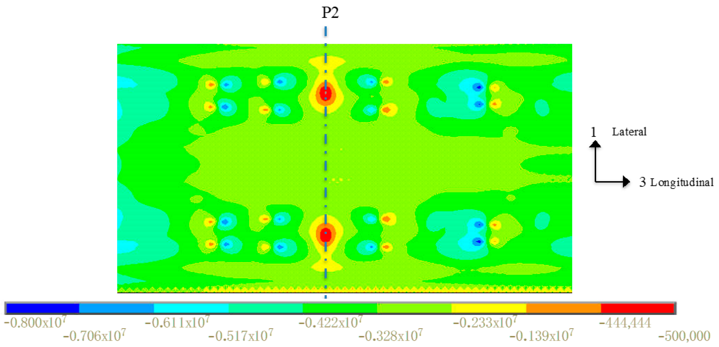
4.3. Long-Term Behaviour
5. Parametric Studies
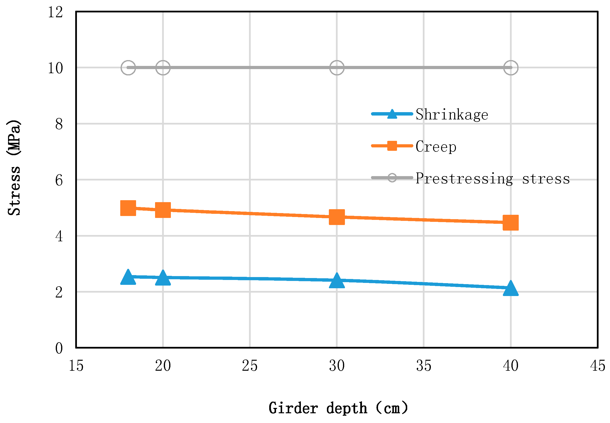
5.1. Girder Depth
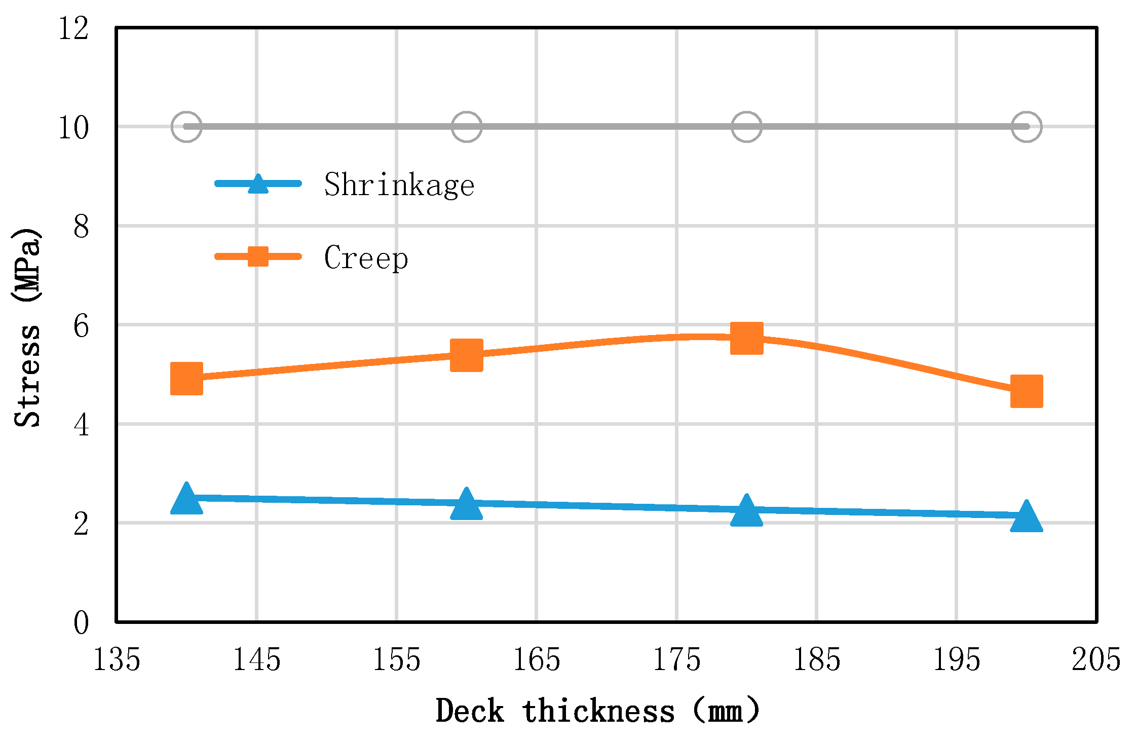
5.2. Deck Thickness
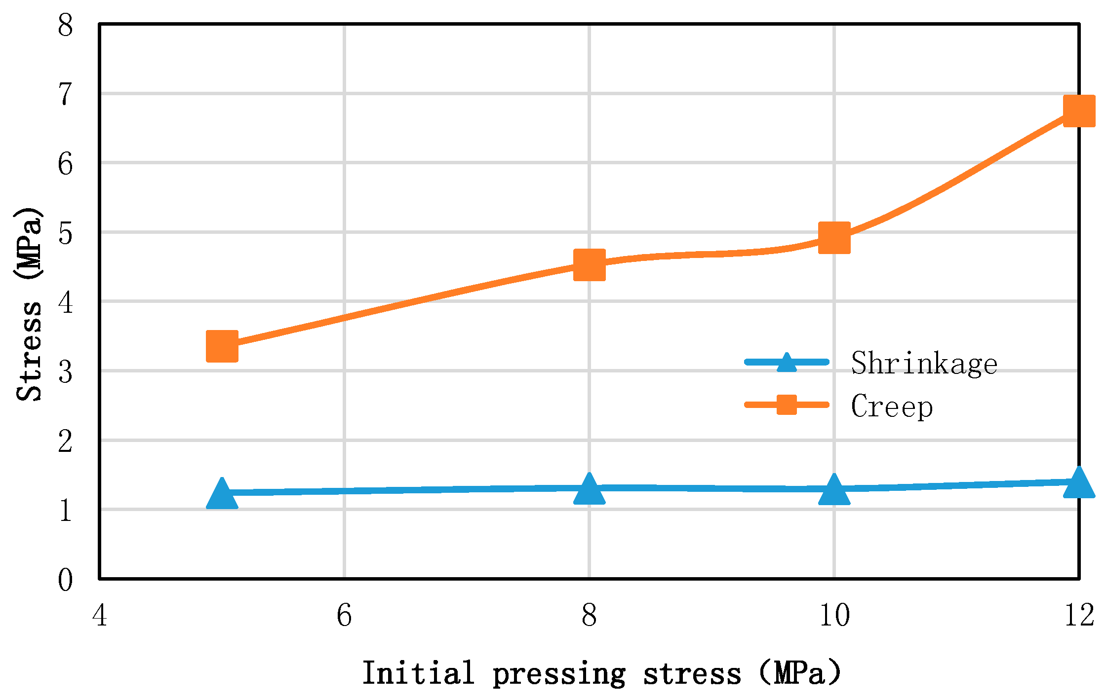
5.3. Prestressing Stress
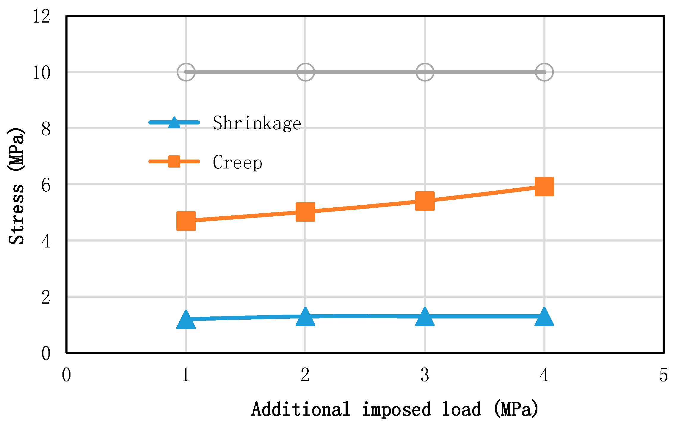
5.4. Additional Imposed Load
6. Conclusions
- (1)
- For the continuous twin-I girder bridge, the prestressed tendons introduce compressive stress in the concrete deck and the compressive stress under constructed condition is big and it can overcome the tensile stress induced by shrinkage and live load.
- (2)
- In the hogging regions, the prestressed stresses in the concrete deck are reduced due to the concrete creep effect and the decrease is up to 50% of the initial prestressing stress.
- (3)
- The stresses in the steel girders in the hogging regions vary big, especially for girder flange in tension and the changes are due to force transfer from compressive stress in concrete deck.
- (4)
- The stresses in the tendons have almost no change and the prestressed force transfers from concrete deck to steel girders in the hogging regions.
- (5)
- The steel girder stiffness has no effect on the prestressing stress loss in the concrete deck.
- (6)
- The concrete deck, initial prestressing stress and additional imposed load have an effect on the initial prestressing stress loss in the concrete deck due to concrete creep.
- (7)
- The prestressing stress loss in the concrete due to creep mostly is over 50% and it is transferred to steel girders to change the stress distribution of composite section in the hogging regions.
Author Contributions
Funding
Conflicts of Interest
References
- Gara, F.; Leoni, G.; Dezi, L. Slab cracking control in continuous steel-concrete bridge decks. J. Bridge Eng. 2013, 1319–1327. [Google Scholar] [CrossRef]
- Macorini, L.; Fragiacomo, M.; Amadio, C.; Izzuddin, B.A. Long-term analysis of steel–concrete composite beams: FE modeling for effective width evaluation. Eng. Struct. 2006, 28, 1110–1121. [Google Scholar] [CrossRef]
- Oehlers, D.J.; Bradford, M.A. Composite Steel and Concrete Structures: Fundamental Behavior; Elsevier: Oxford, UK, 2013. [Google Scholar]
- Ryu, H.K.; Chang, S.P.; Kim, Y.J.; Kim, B.S. Crack control of a steel and concrete composite plate girder with prefabricated slabs under hogging moments. Eng. Struct. 2005, 27, 1613–1624. [Google Scholar] [CrossRef]
- Xia, Y.; Wang, P.; Sun, L. Neutral axis position based health monitoring and condition assessment techniques for concrete box girder bridges. Int. J. Struct. Stab. Dyn. 2019, 19. [Google Scholar] [CrossRef]
- Xia, Y.; Nassif, H.; Su, D. Early-age cracking in high performance concrete decks of typical Curved steel girder bridges. J. Aerosp. Eng. (ASCE) 2017, 30, B4016003. [Google Scholar] [CrossRef]
- Miyamoto, A.; Tei, K.; Nakamura, H.; Bull, J. Behavior of prestressed beam strengthened with external tendons. J. Struct. Eng. 2000, 1033–1044. [Google Scholar] [CrossRef]
- Deng, Y.; Morcous, G. Efficient prestressed concrete-steel composite girder for medium-span bridges. I: System description and design. J. Bridge Eng. 2013, 1347–1357. [Google Scholar] [CrossRef]
- Deng, Y.; Morcous, G. Efficient prestressed concrete-steel composite girder for medium-span bridges. II: Finite-element analysis and experimental investigation. J. Bridge Eng. 2013, 1358–1372. [Google Scholar] [CrossRef]
- Wang, X.; Shi, J.; Wu, G.; Yang, L.; Wu, Z. Effectiveness of basalt FRP tendons for strengthening of RC beams through the external prestressing technique. Eng. Struct. 2015, 101, 34–44. [Google Scholar] [CrossRef]
- Marí, A.; Mirambell, E.; Estrada, I. Effects of construction process and slab prestressing on the serviceability behaviour of composite bridges. J. Constr. Steel Res. 2003, 59, 135–163. [Google Scholar] [CrossRef]
- Dezi, L.; Gara, F.; Leoni, G. Construction sequence modeling of continuous steel-concrete composite bridge decks. Steel Compos. Struct. 2006, 6, 123–138. [Google Scholar] [CrossRef]
- Liu, X.; Liu, Y.; Luo, J.X.H. Behavior of Continuous Composite Bridge during Construction with Jacking up Interior Support, National Bridge Conference 2012, pp. 658–662, 2012. (In Chinese). China Highway and Transportation Society. Available online: http://caj.d.cnki.net//KDoc/docdown/pubdownload.aspx?dk=kdoc%3apdfdown%3aa31df52a5345b1bdc7ff1d792e853f28 (accessed on 12 November 2018).
- Kwon, G.; Engelhardt, M.D.; Klingner, R.E. Behavior of post-installed shear connectors under static and fatigue loading. J. Constr. Steel Res. 2010, 66, 532–541. [Google Scholar] [CrossRef]
- Hällmark, R.; Collin, P.; Möller, M. The behaviour of a prefabricated composite bridge with dry deck joints. Struct. Eng. Int. 2013, 23, 47–54. [Google Scholar] [CrossRef]
- Su, Q.; Yang, G.; Bradford, M. Behavior of a continuous composite box girder with a prefabricated prestressed-concrete slab in its hogging-moment region. J. Bridge Eng. 2015, B4014004. [Google Scholar] [CrossRef]
- Tong, T.; Yu, X.; Su, Q. Coupled effects of concrete shrinkage, creep, and cracking on the performance of postconnected prestressed steel-concrete composite girders. J. Bridge Eng. 2017. [Google Scholar] [CrossRef]
- Ministry of Construction of the People’s Republic of China. Code for Design of Concrete Structures; GB50010-2010; Ministry of Construction of the People’s Republic of China: Beijing, China, 2015. [Google Scholar]
- Ministry of Transport of the People’s Republic of China. Chinese Code for Design of Highway Reinforced Concrete and Pre-Stressed Concrete Bridge and Culverts Beijing; JTG D62-2004; Ministry of Transport of the People’s Republic of China: Beijing, China, 2004. [Google Scholar]
- Ministry of Transport of the People’s Republic of China. Code for Design of Highway Reinforced Concrete and Prestressed Concrete Bridges and Culverts; JTG D62-2012; Ministry of Transport of the People’s Republic of China: Beijing, China, 2012. [Google Scholar]
- ANSYS Release 12.0 [Computer Software, Version 12.0]; ANSYS, Inc.: Canonsburg, PA, USA, 2009.
- ANSYS, Inc. ANSYS Manual; ANSYS, Inc.: Canonsburg, PA, USA, 2009. [Google Scholar]
- Pan, H.; Azimi, M.; Yan, F. Time-Frequency-Based Data-Driven Structural Diagnosis and Damage Detection for Cable-Stayed Bridges. J. Bridge Eng. 2018, 23, 04018033. [Google Scholar] [CrossRef]
- Ministry of Construction of the People’s Republic of China. Code for Design of Steel Structures; GB50017-2003; Ministry of Construction of the People’s Republic of China: Beijing, China, 2003. [Google Scholar]
- Ministry of Construction of the People’s Republic of China. Code for Design of Steel and Concrete Composite Bridges; GB50917-2013; Ministry of Construction of the People’s Republic of China: Beijing, China, 2013. [Google Scholar]
- Oh, B.; Sause, R. Empirical Models for Confined Concrete under Uniaxial Loading. In International Symposium on Confined Concrete; ACI SP-238; American Concrete Institute: Farmington Hills, MI, USA, 2006; pp. 141–156. [Google Scholar]


| Analysis Result | Prestressed Concrete Deck Condition | Constructed Condition | 10,000-Day Creep | |
|---|---|---|---|---|
| Concrete deck | Bottom surface | −7~−8 MPa | −4.4~−6.2 MPa | −2.3 MPa~−3.3 MPa |
| Top surface | −6~−7 MPa | −4.7~−5.6 MPa | −2.6 MPa~−3.5 MPa | |
| Steel girder | Top flange | 135 Mpa | 165 MPa | 10–20 MPa |
| Bottom flange | 143 MPa | 167 MPa | 155–165 MPa | |
| Tendons | - | 1135–1175 MPa | 1115–1180 MPa | |
| Deflection | 0.066 m | 0.074 m | 0.040 m | |
© 2018 by the authors. Licensee MDPI, Basel, Switzerland. This article is an open access article distributed under the terms and conditions of the Creative Commons Attribution (CC BY) license (http://creativecommons.org/licenses/by/4.0/).
Share and Cite
Ma, H.; Shi, X.; Zhang, Y. Long-Term Behaviour of Precast Concrete Deck Using Longitudinal Prestressed Tendons in Composite I-Girder Bridges. Appl. Sci. 2018, 8, 2598. https://doi.org/10.3390/app8122598
Ma H, Shi X, Zhang Y. Long-Term Behaviour of Precast Concrete Deck Using Longitudinal Prestressed Tendons in Composite I-Girder Bridges. Applied Sciences. 2018; 8(12):2598. https://doi.org/10.3390/app8122598
Chicago/Turabian StyleMa, Haiying, Xuefei Shi, and Yin Zhang. 2018. "Long-Term Behaviour of Precast Concrete Deck Using Longitudinal Prestressed Tendons in Composite I-Girder Bridges" Applied Sciences 8, no. 12: 2598. https://doi.org/10.3390/app8122598
APA StyleMa, H., Shi, X., & Zhang, Y. (2018). Long-Term Behaviour of Precast Concrete Deck Using Longitudinal Prestressed Tendons in Composite I-Girder Bridges. Applied Sciences, 8(12), 2598. https://doi.org/10.3390/app8122598