Review

In-Situ Nanoparticles: A New Strengthening Method for Metallic Structural Material

1
State Key Laboratory for Advanced Metals and Materials, University of Science and Technology Beijing, Beijing 100083, China
2
School of Materials Science and Engineering, University of Science and Technology Beijing, Beijing 100083, China
3
Department of Materials Science and Engineering, KTH Royal Institute of Technology, SE-100 44 Stockholm, Sweden
4
Institute for Advanced Materials and Technology, University of Science and Technology Beijing, Beijing 100083, China
*
Authors to whom correspondence should be addressed.
Appl. Sci. 2018, 8(12), 2479; https://doi.org/10.3390/app8122479
Submission received: 29 October 2018 / Revised: 23 November 2018 / Accepted: 23 November 2018 / Published: 3 December 2018
(This article belongs to the Section Nanotechnology and Applied Nanosciences)

Abstract

:
Over the past several years, coherent interface strengthening was proposed and has since drawn much attention. Unfortunately, many fabrication techniques are restricted to very small size. Recently, a brand new method of in-situ nanoparticle strengthening was systematically investigated, which was proved to be an efficacious way to optimize microstructure and improve mechanical property by utilizing uniformly dispersed nanoparticles. In this review, we summarized recent related advances in investigated steels and Cu alloys, including details of preparation technique and characterization of in-situ nanoparticles. In-situ nanoparticles formed in the melt possess a coherent/semi-coherent relationship with the matrix, which has a similar effect of coherent interface strengthening. In this case, bulk metallic structural materials with dispersed nanoparticles in the matrix can be fabricated through conventional casting process. The effects of in-situ nanoparticles on grain refinement, inhibiting segregation, optimizing inclusions and strengthening are also deeply discussed, which is beneficial for obtaining comprehensive mechanical response. Consequently, it is expected that in-situ nanoparticle strengthening method will become a potential future direction in industrial mass production.

1. Introduction

Metallic structural materials, such as steel, Cu alloys, Mg alloys and Al alloys, have been widely used in ships, cars, aerospace planes and other manufacturing industries [1,2,3,4,5]. With rapid development of modern science and technology, there are increasing demands for mass-produced metal materials with higher strength. However, strengthen methods for metals usually lead to a pronounced decrease in plasticity. Hence, Lu [6] recently proposed that excellent comprehensive mechanical performance is the development trend of metal materials in the future.
Mechanical properties of material depend on its microstructure, which can be optimized in order to obtain better comprehensive mechanical response. Grain refinement and second phase strengthening are important approaches that simultaneously improve both strength and plasticity, which are widely used in metal reinforcement. In the classic case of grain refinement strengthening, as described by Hall–Petch relationship, increase in strength is proportional to the reciprocal square root of the grain size [7,8]. In addition, ultrafine crystalline materials (grain size: 100~1000 nm) exhibit ultra-high strength at room temperature and ultra-high plasticity at high temperature [9], which can be manufactured by severe plastic deformation (SPD), such as equal channel angular pressing (ECAP) [10,11,12,13,14] and high pressure torsion (HPT) [15,16,17]. Regrettably, samples processed by SPD are always limited in millimeter-sized scale and cylinder or cuboid shape. As for solidification processing, it was reported that adding nucleating agents to metal melt [18] and various casting techniques [19,20,21], such as centrifugal casting, die-casting, squeeze-casting and ultrasonic vibration casting, have been developed in order to modify the microstructures with finer grains (about 100 μm). In that case, strengthening effect is not remarkable because grain size is still large. In particular, spray forming [22,23], a novel rapid solidification technique which has quickly developed in recent decades, can refine grain size to 15–20 μm but still has limitations in size and volume [24]. Therefore, fabrication of bulk metallic structural materials with very fine grains in industrial mass production is still a problem.
Second phase strengthening is an important reinforcement approach for as-cast metallic ingots [25,26], which are generally strengthened by dispersed micron/sub-micron particles, thus to dramatically reduce the plasticity especially for ceramic-type strengthening particles in high concentration [27,28,29,30,31,32]. According to the Orowan-Ashby model, the refinement of the second phase is conducive to both strength and plasticity for materials [25,33,34,35,36]. When the particles are refined to nanometer scale, the second phase/matrix interface turns to be coherent or semi-coherent and therefore the interaction mode between dislocations and the second phases will change [37]. In other words, in the process of particles blocking dislocation motion, some dislocations enter the interior of particles along the coherent interface, which reduces the dislocation accumulation and meanwhile improves the macroscopic strength and plasticity of alloys [38]. As a result, overall mechanical performance of metals can be improved when refining second phase to the nanometer level [33,38,39,40,41,42]. With more quantities and homogeneous distribution of nanoparticles in the matrix, not only better strengthening effect but also lower damage to the elongation can be achieved.
Powder metallurgy and internal oxidation are often used to fabricate dispersion-strengthened alloys [27,43,44,45,46]. However, these methods are difficult to be applied in mass production of bulk material due to complex fabrication process, high cost and high energy consumption [27]. In addition, mechanical alloying materials yield holes during subsequent high-temperature heat treatment, which significantly deteriorate the mechanical properties [47]. In contrast, fabrication of in-situ nanoparticles by conventional casting process is more feasible. As noted recently, second phase particles are expected to in-situ form in metal melt with nanoscale to realize dispersion strengthening. Simultaneously, these in-situ particles can act as nucleation sites during solidification process so as to realize the grain refinement. In-situ nanoparticles are more favorable than ex-situ nanoparticles, due to their uniform distribution and coherent or semi-coherent relationship with the matrix. In contrast, heterogeneous distribution and larger size scale (0.1–1 μm, incoherent) of the ex-situ nanoparticles both always lead to unsatisfied mechanical response [27,43,44,45,46,47,48,49,50]. In addition, coherent or semi-coherent interface reduces the interfacial energy between particle and matrix, which results in increasing stability of particles. With respect to the fabrication process, the endogenous method is more low-cost, time saving and effective compared to external adding.
In this review, we give a brief description of an innovative strengthening method of in-situ nanoparticles fabricated during conventional casting process by an overview of the fundamental and technical methods used for the fabrication and characterization of in-situ nanoparticles. Examples of in-situ nanoparticles applications in steel and Cu alloys are elaborately discussed in the context of fabrication techniques, their microstructure and mechanical properties. In-situ nanoparticles prepared in this way are uniformly dispersed and present a coherent/semi-coherent relationship with the matrix, indicating a remarkable strengthening effect akin to coherent interface strengthening. Effects of in-situ nanoparticles on grain refinement, inhibiting segregation and optimizing inclusions are also deeply discussed, which are conducive to plasticity. In a nutshell, this brand new in-situ nanoparticle strengthening method provides a guideline for fabricating strong and ductile bulk metals and it is expected to become a potential future direction in industrial mass production.

2. Strengthening Mechanism of In-Situ Nanoparticles

Traditionally, structural metallic materials achieve higher strength by sacrificing plasticity. However, coherent interface strengthening mechanism is a new strategy to overcome this shortcoming and improve the strength and toughness simultaneously. Lu et al. [37] reported that coherent nano-twin boundaries in Cu not only block dislocations movement but also act as slip planes so that dislocations could pass. The interface has three key features: (1) being crystallographic semi-coherent/coherent with the matrix, (2) owning good thermal stability and mechanical stability, (3) with nanometer order size (<100 nm). Similarly, in our recent research, we found that in-situ nanoparticles possess these same features, which is disparate from other endogenous particles fabricated by conventional methods. As shown in Figure 1, in-situ nanoparticles have coherency relationship with the matrix. Figure 1a shows dislocations inside the nanoparticle and at interface. It can be assumed that when the slipping dislocations meet these nanoscale coherent interfaces, they will slip along the coherent interface and enter into the nanoparticles easily due to the low mismatch and little lattice distortion. Some dislocations can be retained inside the nanoparticles and at the phase boundaries, which is conducive to the enhancement in strength. Others can move through the coherent interface and slip to the adjacent nanoparticles, thus stress concentration at the matrix-particle interface intersection could be efficaciously released, resulting in considerable plastic strain.
Classical strengthening mechanisms generally depend on defects in materials, the resistance of defects to dislocation motion results in an increase in strength during deformation. Whereas, the coherent interface strengthening mechanism can ameliorate this phenomenon. Actually, stress concentration still exists in materials. However, the dislocation density and stress concentration in the matrix can be dispersed by the uniformly distributed nanoparticles when the amount of dislocations is constant. In other words, the distribution of dislocations in materials is improved so that the reduction of plasticity caused by dislocation entanglement is weakened, and finally the strength and ductility get improved simultaneously. The corresponding details are illustrated in references [38,40,41].

3. Materials Fabrication

As results of an endogenous method, large amounts of in-situ nanoparticles (5–50 nm) generally form in liquid melt during solidification process and exist in the matrix of as-cast ingots. In-situ nanoparticles generally own several characteristics: uniform distribution inside the alloy matrix, excellent wettability between particles and molten alloy, semi-coherent or coherent interface between particles and matrix. According to Gleiter’s theory [51], in-situ nanoparticle reinforced materials belong to nanostructured materials, and we firstly started the investigation on Cu-3Sn-8Zn-6Pb-1Fe alloy in 2009 [40].
There are several key points to obtain myriads of in-situ nanoparticles through casting process. Firstly, it is necessary to add suitable alloying elements with the function of precipitation strengthening. Thermodynamic calculation needs to be conducted to ensure that nanoparticles meet the requirement of precipitation kinetics during solidification. In addition, it should be noted that an in-situ nanoparticle generally owns higher melting point than that of the base metal so as to nucleate prior to the base metal. As a result, theoretical basis for the selection of alloying elements is provided.
In addition, appropriate casting technique should be carried out to control the nucleation and growth process of nanoparticles in order to obtain superior microstructure. Although the strengthening elements-containing particles can nucleate in base metal liquid, the radius of particles is mainly affected by the critical nucleation radius and growth rate. The critical nucleation radius should be limited at nanoscale which is the premise of ensuring that the particles maintaining at nanometer size during subsequent growth process. In addition, it is essential to keep nanoparticles from growing too fast during solidification and cooling, so nanoscale particles can be finally obtained [40]. In addition, the distribution of the nanoparticles in matrix is another important issue. Some relatively concentrated distribution forms, such as clusters and chains, are supposed to be prohibited. On the contrary, a diffuse and uniform distribution of nanoparticles is preferable. This is because the existence forms of particles in the matrix, such as the shape, size, quantity and distribution, play a decisive role in mechanical properties. In this section, elaborate theoretical calculations and fabrication techniques of in-situ nanoparticle reinforced steel and Cu alloys are presented.

3.1. In-Situ Nanoparticle Reinforced Steel

3.1.1. Thermodynamic Calculation

We have applied the in-situ nanoparticles reinforcement technology in low carbon steel [52,53,54,55], ship building steel [33,56,57] and naval steel [58]. Titanium (Ti) was selected as the main forming element of microalloying in-situ nanophase in our research. On one hand, Ti can act as the deoxidizer effectively in molten steel in that the affinity of Ti with O is higher than that with N, S and C which generally exist in steels. On the other hand, with optimized amount, Ti was conducive to forming large amounts of nano-oxide second phase which evenly distribute in the melt at the same time [59]. Therefore, mechanical properties of steels are expected to be distinctly improved.
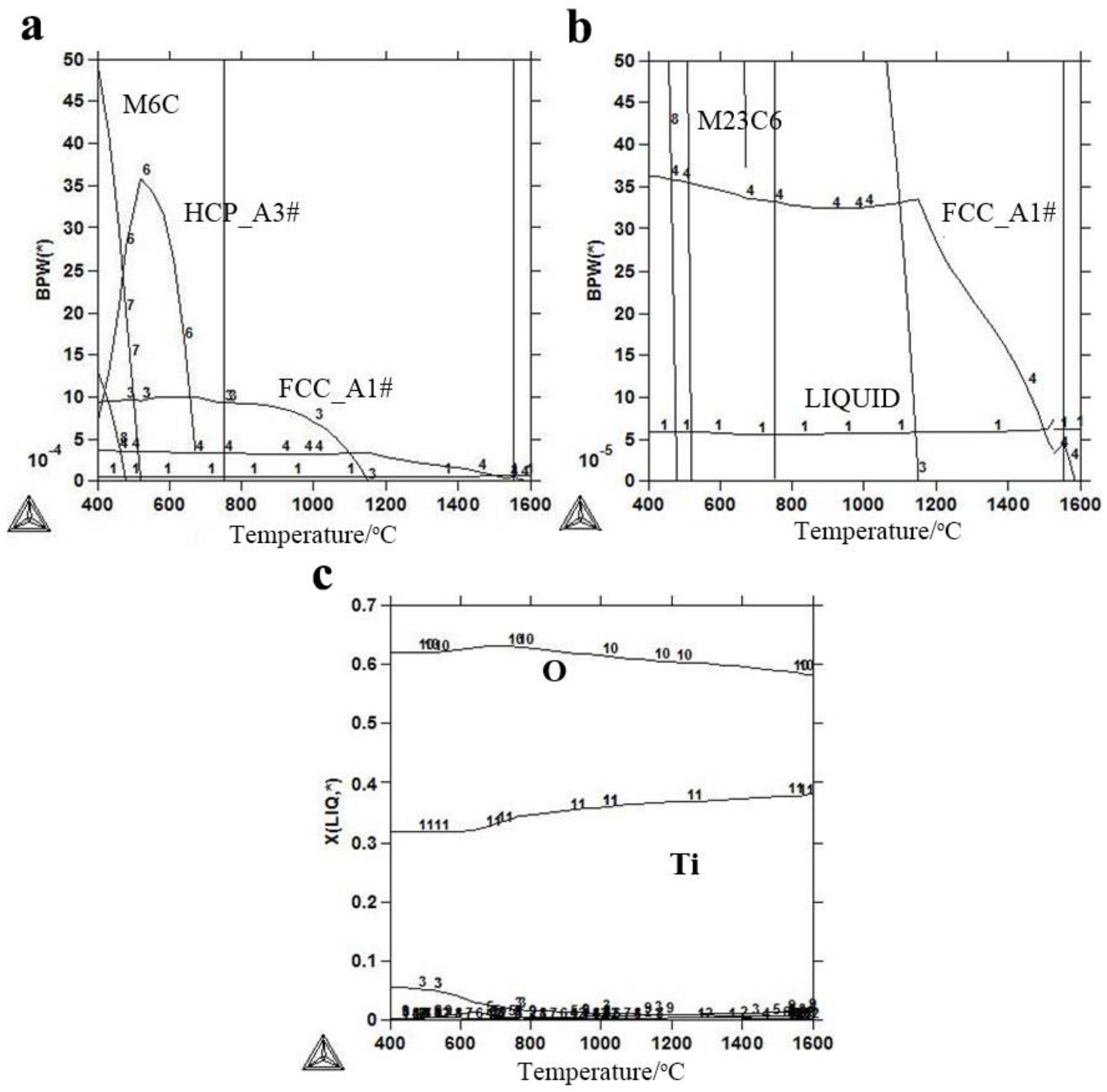
Thermo-Calc software was used to calculate the thermodynamic equilibrium phase in Ti microalloying steel and investigate the precipitated phases with specific element composition of each phase existed in steel. As an example, the calculation results of the Ni–Cr–Mo HSLA steel with Ti addition are listed in Figure 2 and calculated temperature interval is 400 °C~1600 °C. Corresponding details of composition and calculating parameter could be found in ref [59]. Figure 2a,b show the precipitated phase composition diagram of Ti microalloying steel. The precipitation temperatures of main phases arrange as LIQUID>FCC_A1#3>FCC_A1#2>HCP_A3#1>M6C>M23C6. The Ti-containing precipitated phase should be mainly considered in the analysis. The FCC_A1#2 phase contains carbide and nitride of Ti/Nb and the precipitation temperature is about 1150 °C. The FCC_A1#3 phase consists of titanium carbide and titanium nitride, which has the higher precipitation temperature around 1580 °C. Specifically, composition diagram of liquid phase is displayed in Figure 2c and it can be observed that Ti and O elements always exist in the liquid phase. This phenomenon indicates that Ti reacted with O element in the molten steel to form titanium oxide at exactly the time when Ti wires were added into the melt. Once titanium oxide forms in the melt, it remains in the matrix after solidification. Hence, calculated results show that it is possible to obtain in-situ titanium oxide particles in the melt during casting process.
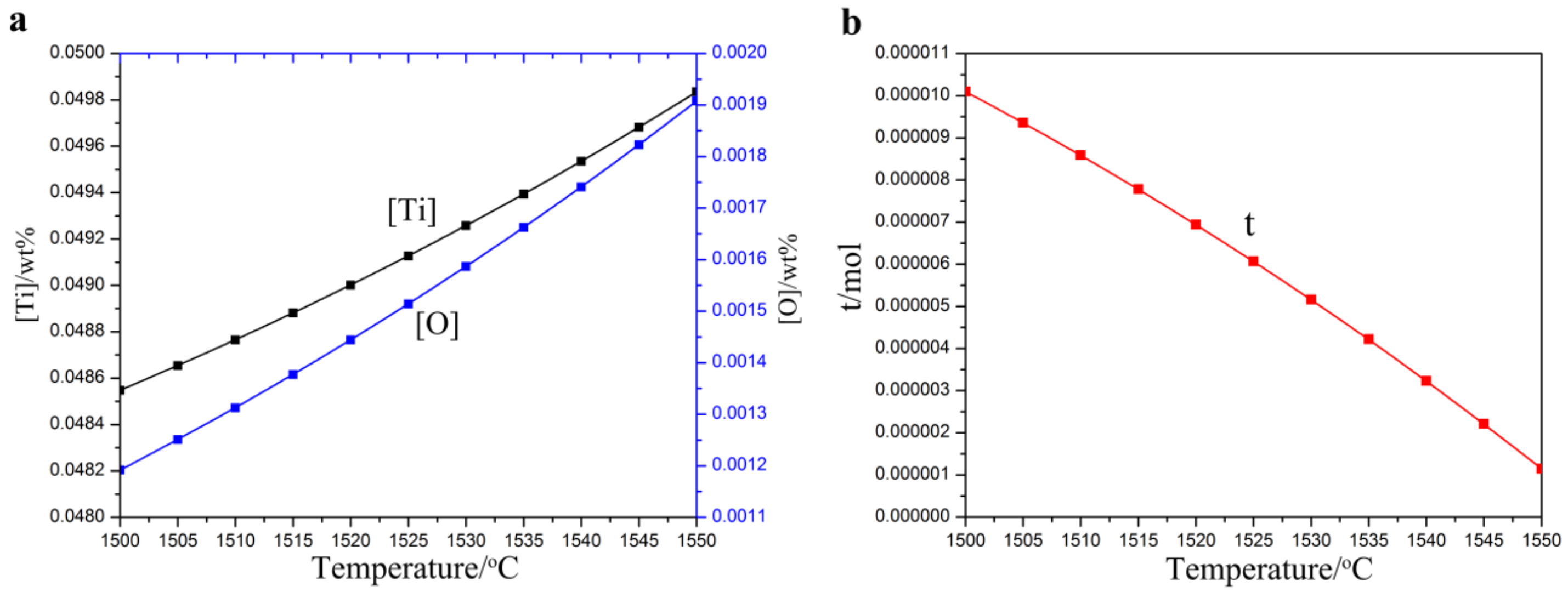
To investigate the size of titanium oxide particles, thermodynamic analysis of Ti3O5 precipitates was performed in Ti0.05%-O0.002% steel system. The calculation result shows that entire solid solution temperature (TAN) is 1555.21 °C and liquid temperature is 1512.75 °C [59]. Reaction of Ti and O starts immediately when Ti is added into the melt, resulting in Ti3O5 precipitates. The solubility of Ti, O ([Ti], [O]) and molar fraction of precipitates in high-strength steel changes as a function of temperature is shown in Figure 3a,b, respectively. The solubility of Ti and O elements reduces with the decrease of temperature, while the total molar fraction t of Ti3O5 precipitate increases with the decrease of temperature. At 1510 °C, [Ti] is 0.04876519%, [O] is 0.00131259% and molar fraction t of Ti3O5 precipitate is 8.592 × 10⁻⁶ mol, which indicates that the molar fraction of Ti3O5 precipitate is small during the solidification process [59]. If we choose suitable casting technique to render such a small molar fraction of Ti3O5 to homogeneously distribute in so wide a range of molten steel, these in-situ Ti3O5 particles are expected to be in nanosize.

3.1.2. Fabrication Technique

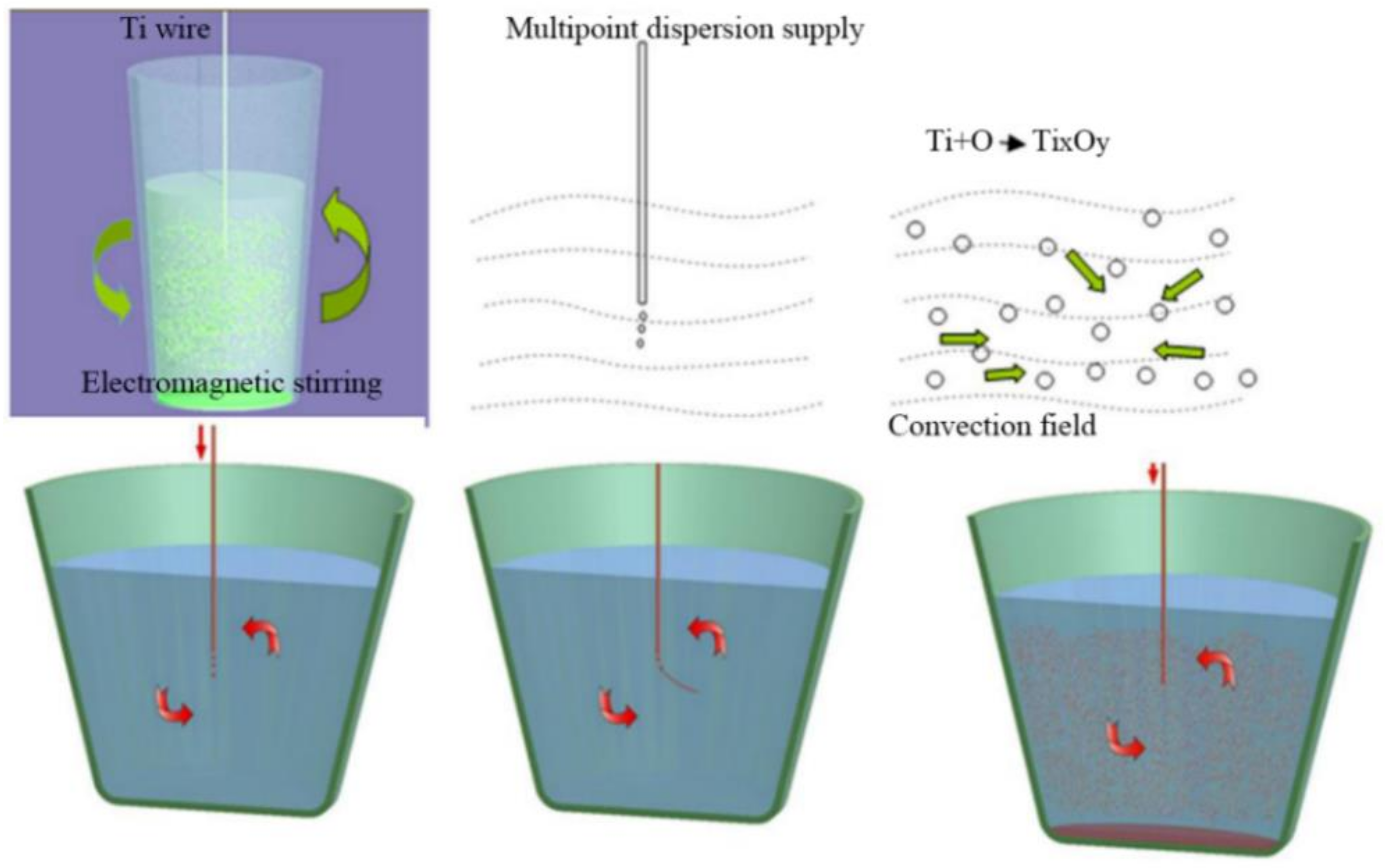
As schematically shown in Figure 4, in-situ nanoparticle reinforced steel was fabricated by a special casting process with combination of multipoint dispersion supply and electromagnetic stirring [33]. Two key factors should be considered. Firstly, when Ti wires were added into molten steel, the tips began to melt and reacted rapidly with the dissolved O in the steel to form titanium oxide, resulting in large amounts of nanoparticles. As the growth mode of these nanoparticles is typical diffusion control growth [60,61], the main control factor is the solute content of O and Ti in steel. The dissolved O content in steel is rather low (generally lower than 40 PPM), and thus the growth process of generated titanium oxide nanoparticles is mainly controlled by the solute element Ti. Therefore, uniform multipoint dispersion supply processing was carried out by addition of many Ti wires which are arranged uniformly in the space. As a result, excessive concentration of solute elements will not happen and the growth rate of titanium oxide nanoparticles can be controlled well. Secondly, electromagnetic stirring (or argon blowing) was applied in the smelting process, resulting in flow field and force field existed in the melt. In this case, the newly formed in-situ nanoparticles were quickly taken out of initial area and dispersed homogeneously inside the steel melt. Thus it is very difficult for nanoparticles to grow with sufficient supply of solute element Ti.

3.2. In-Situ Nanoparticle Reinforced Cu Alloys

3.2.1. Thermodynamic Calculation

Fe and Co elements are selected to be added into Tin bronze and pure Cu during the casting process in order to fabricate in-situ nanoparticle reinforced Cu alloys with NPFG structure, which has numerous iron-rich nanoparticles (NP) dispersed within fine grains (20–40 µm, FG) [38,40,41,62,63,64,65,66,67,68,69,70]. The NPFG structure is in-situ formed during the casting process, so it can be widely applied in mass production of metallic structural material with complex shapes.
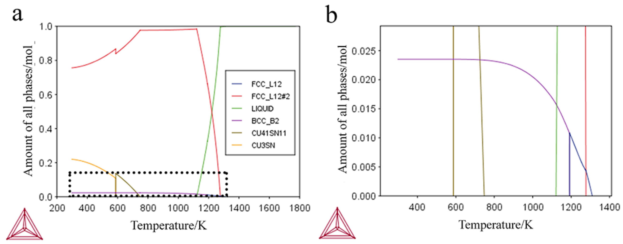
Thermo-Calc software was used to calculate how the equilibrium molar fraction of each phase changes as the melt cools down to room temperature in Cu-10Sn-2Zn-1.5Fe-0.5Co alloy (Figure 5). It is obvious that in the equilibrium state FCC_L12 phase first precipitates in the form of face-centered cubic (FCC) structure from the melt with the starting temperature of 1310 K. Cu matrix (FCC_L12#2 phase) begins to solidify when the molten alloy cooled down to 1277 K, accompanying with the precipitation and growth of FCC_L12 phase. When temperature decreases to 1192 K, phase transition happens from FCC_L12 phase to BCC_B2 phase. Subsequently, the iron-rich phase continues to precipitate and grows as BCC structure. Compositions of these phases at different temperatures were calculated by using “Single Point Equilibrium” module and the results in Table 1 show that both the FCC and BCC iron-rich phases are mainly composed of Fe and Co elements, and the ratio of Fe/Co is about 3/1 [71].
Precipitation behavior of iron-rich phase in Cu-10Sn-2Zn-1.5Fe-0.5Co solid matrix was also calculated by using “Precipitation Simulation” module [71]. The iron-rich phase is always regarded as spherical shape without considering the morphological evolution. At ambient temperature, the iron-rich phase has double-peak size distribution, including small particles with radius less than 2 nm and large particles with radius of 5~80 nm. The number of the small particles is 103~104 times bigger than that of the large ones, which is consistent with the 3DAP (3 Dimentional Atom Probe) and TEM (Transimission Electron Microscope) characterization results [69]. TCAL4 database in Thermo-Calc package was used to calculate size distribution at room temperature and the average radius evolution of iron-rich phase (BCC_B2) in the solid matrix of Cu-10Sn-2Zn-1.5Fe-0.5Co alloy with cooling rate of 1.4 K/s from 1310 to 293 K [71]. Average size evolution of nanoparticles shows that above 800 K, the iron-rich phase precipitates and grows with average size slowly increasing, which may be caused by long-term diffusion. Under 800 K, myriads of new iron-rich phase precipitate with small size through short-term diffusion or spinodal decomposition due to the lack of conditions for long-term diffusion. In this case, it is difficult for the precipitates to grow up to large scale, resulting in a sharp decline in average size, which is also an important reason for the formation of double-peak size distribution.

3.2.2. DSC (Differential Scanner Calorimetry) Analysis

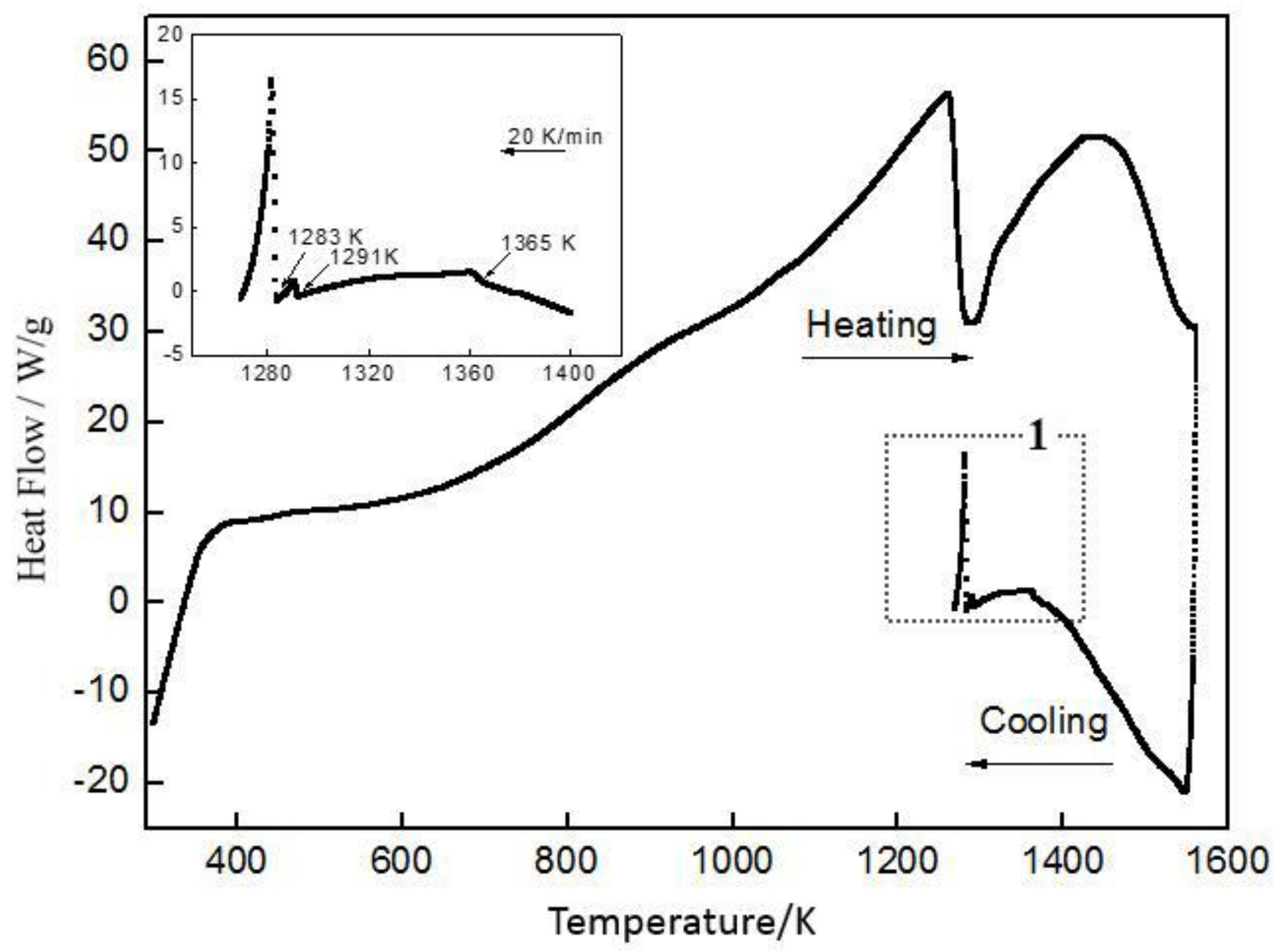
Precipitation behavior of iron-rich nanoparticles during solidification was investigated by DSC thermal analysis, as shown in Figure 6 [64]. The as-cast Cu-10Sn-2Zn-1.5Fe-0.5Co alloy was melted and heated until 1573 K, and then cool down at a rate of about 20 K/min. Obviously, there are three exothermic peaks between 1273 K and 1573 K during the cooling process. Peaks at 1291 K and 1283 K correspond to the solidification of primary α-Cu phase and α-Cu + L → β peritectic transformation respectively, which is consistent with previous DSC result of binary Cu–Sn alloy [72]. In the upper-left inset, there is a relatively gentle exothermic peak at 1365 K which is consistent in precipitation temperature shown in Figure 5, revealing that iron-rich nanoparticles can indeed in-situ precipitate before Cu matrix solidifies.

3.2.3. Fabrication Technique

In-situ nanoparticle reinforced Cu alloys can be fabricated by simple casting process. In our research, all as-cast ingot (15 Kg) with NPFG structure was fabricated by centrifugal casting in the vacuum chamber with a medium frequency electrical furnace. Fe, Co were added to the melt at 1573 K and held for 30 min before casting. The fabrication technique is readily applicable to mass production and industrial applications.
Schematic diagram of the preparation technology for tin bronze alloy with NPFG structure is displayed in Figure 7 [64]. Actually, the whole process is very simple, including solid (Fe, Co)-liquid doping, uniform distribution of all atoms, in-situ generation of nanoparticles, formation of Cu adsorption layer, nucleation catalysis by encapsulated nanoparticles. It can be seen that in-situ nanoparticles can act as both grain refiners and dispersion strengthening phase to optimize the microstructure. Apart from ensuring that iron-rich nanoparticles could meet thermodynamic conditions so as to in-situ precipitate as precursor in the melt, appropriate casting technology, such as induction heating and centrifugal casting, should be carried out in order to assure intensive shearing or convection in the liquid metal. Proper size distribution range and spatial distribution of nanoparticles in molten solution can be promoted, resulting in high nucleation efficiency of nanoparticles and intensive nanoparticle-matrix interaction in Brownian motion.

4. In-Situ Nanoparticles

4.1. Nanoparticles in As-Cast Steel

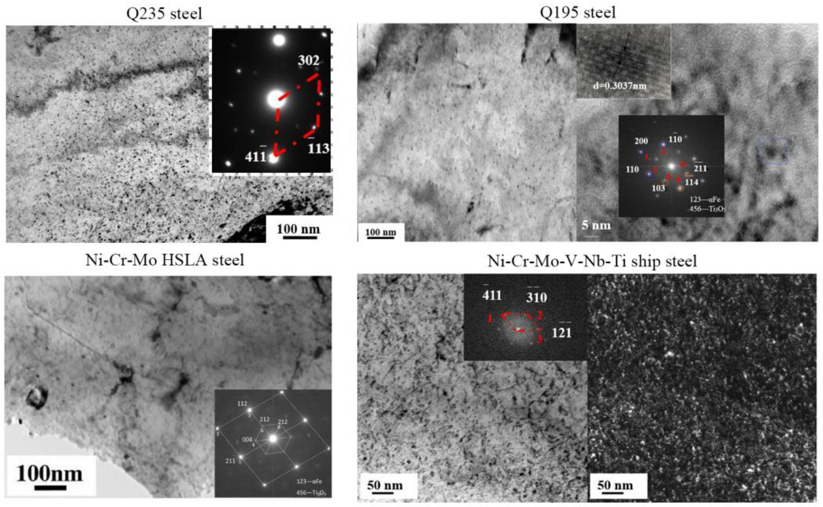
Figure 8 shows representative TEM micrograph of thin foil specimens of the investigated as-cast Q235 steel [59], Q195 steel [33], Ni-Cr-Mo HSLA steel [58] and Ni-Cr-Mo-V-Nb-Ti ship steel [59]. Obviously, the matrix of all steels contains large numbers of fine precipitates with about 5–15 nm diameter, and these fine precipitates distribute homogenously in the whole sample. For example, average diameter and volume fraction of the nanoparticles in Q195 steel and Ni-Cr-Mo-V-Nb-Ti ship steel is 6.7 nm, 0.345% and 7.84 nm, 0.654%, respectively. The results fit well with SAXS results delineating mean size and volume fraction of nanoparticles in Ref. [57,58,59]. Combined with the EDS results, diffraction calibration analysis proves that the nanoparticles in all steels are Ti3O5 with monoclinic structure, which usually has a specific crystallographic orientation relationship with α-Fe matrix (bcc structure). For instance, in Ni–Cr–Mo HSLA steel the precipitate and α-Fe matrix exhibit (112)matrix//(212)Ti3O5 relationship [58].
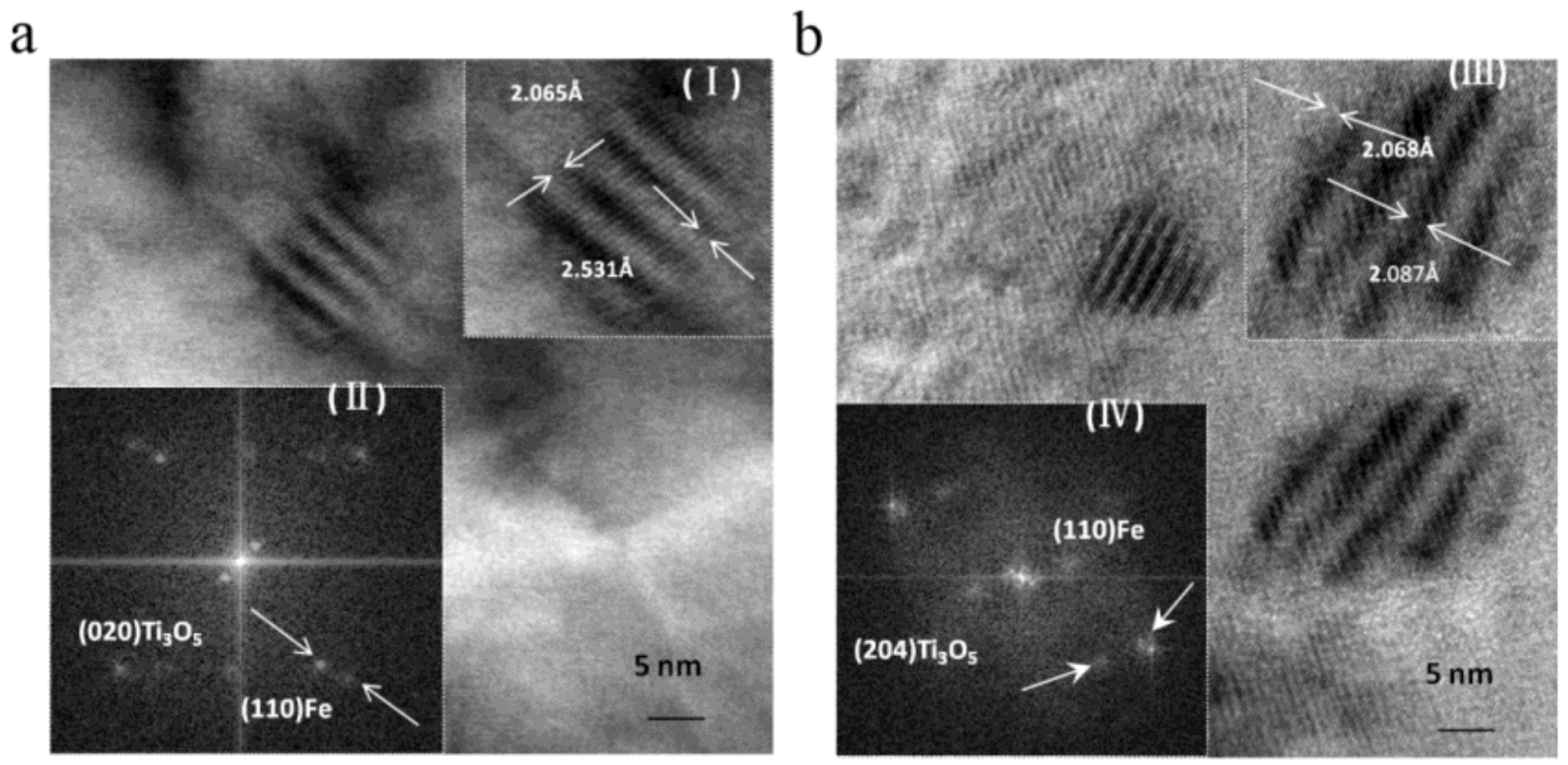
In all investigated as-cast steels, in-situ nanoparticles directly formed in the melt hold coherent or semi-coherent relationship with the matrix. Interestingly, this relationship can be retained after subsequent hot rolling and even high-temperature tempering, which is conducive to improving the comprehensive mechanical properties. Take the Ni-Cr-Mo-V-Nb-Ti ship steel as an example [57]. Representative HRTEM (High Resolution Transmission Electron Microgragh) images of the nanoparticles in as-cast state and 700 °C tempered state are displayed in Figure 9 so as to illustrate the coherency. Morie Patterns can be obviously observed in as-cast and tempered states, which reveals a coherency between the matrix and particles. In addition, coherent relationship could be further confirmed through mismatch degree between particles and the matrix, which can be calculated by the formula [73]:
σ = 2 ( d 1 d 2 ) d 1 + d 2 ,
where σ is the mismatch degree, d1 is the plane spacing of Ti3O5 and d2 is the plane spacing of α-Fe matrix. Misfit parameter for coherent interface is 0–0.05, for semi-coherent interface is 0.05–0.25 and for non-coherent interface is >0.25. Based on the above formula, calculated results present that the mismatch degree of as-cast state and tempered state is 0.202 and 0.009, respectively. So, we can testify that all nanoparticles are coherent with the matrix.
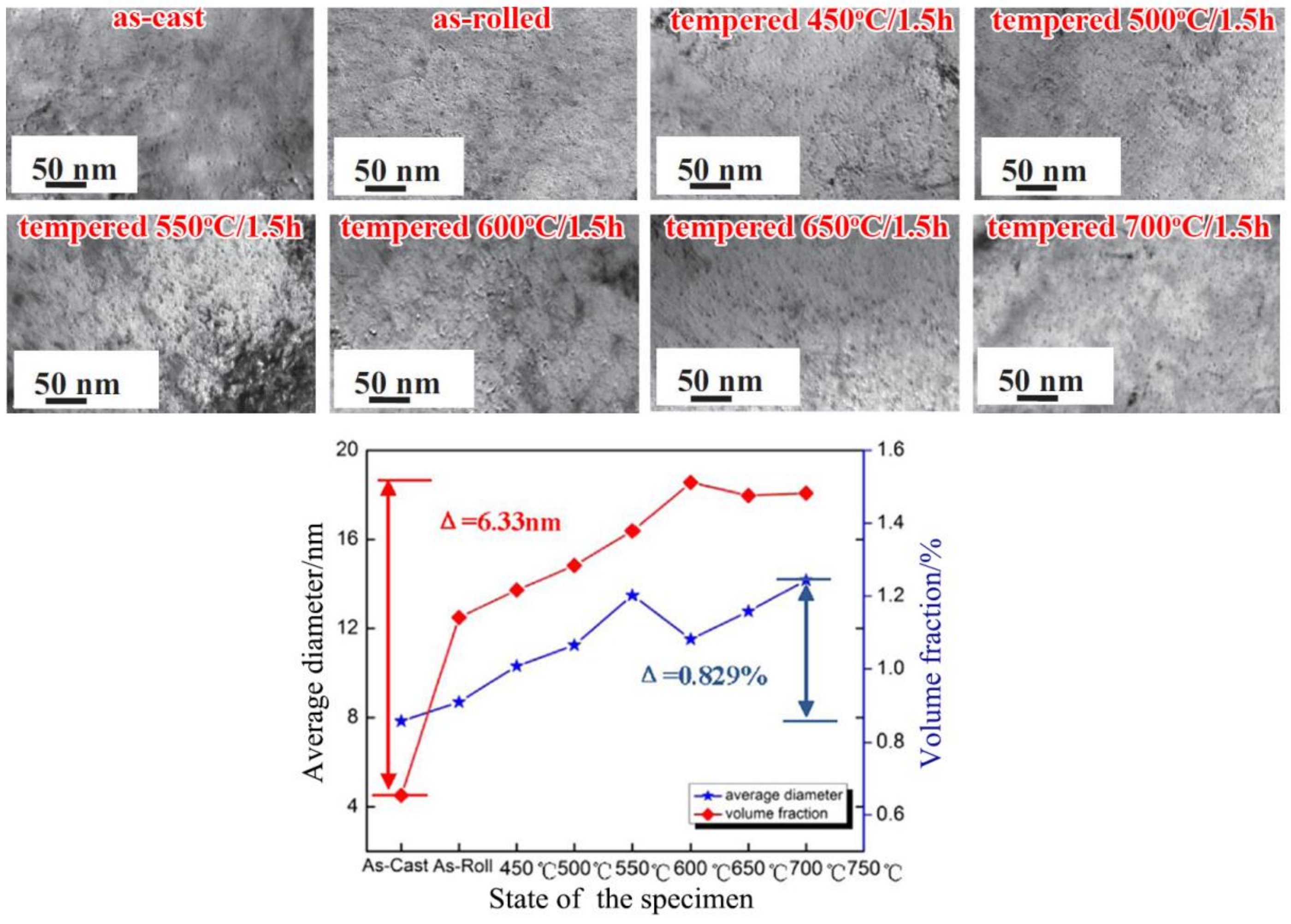
Excellent thermal stability is another advantage of these in-situ nanoparticles. Bright field TEM images and quantitative statistics results of nanoparticles at different states can be seen in Figure 10 [57,59]. TEM micrographs show that the size, shape and distribution of Ti3O5 particles change little from those of the as-cast state to tempered state. From statistics results, we find that the maximum variation of mean radius is 6.33 nm, indicating very little fluctuation of size and less obvious Oswald ripening compared with nano-Cu precipitates in common HSLA steel [74,75,76]. Actually, this growing process is decided by the extremely slow diffusion coefficient of Ti [57,77,78]. Plus, the melting point of Ti3O5 is very high (2180 °C). Hence, we may conclude that the nanoparticles possess outstanding thermal stability. That is why the particles at 700 °C tempered state still have good coherency with the matrix, just as shown in Figure 9. Remarkably, the volume fraction increases distinctly (0.829%) from cast to 700 °C tempered state, due to other carbide precipitation during hot rolling and heat treatment process [57].

4.2. Nanoparticles in As-Cast Cu Alloys

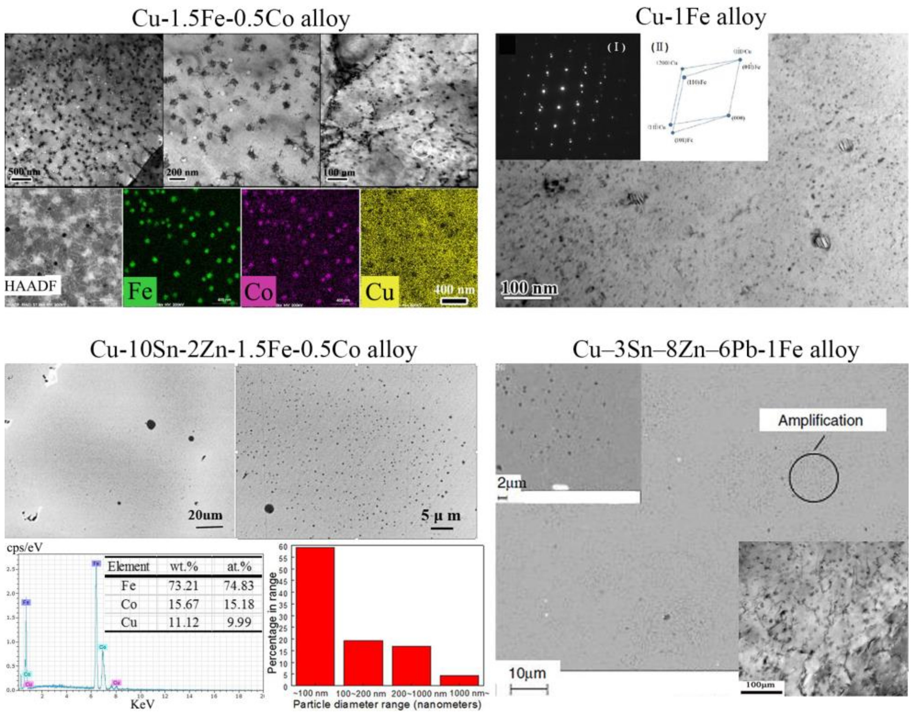
Representative SEM and TEM micrographs of as-cast Cu-1.5Fe-0.5Co alloy [69], Cu-10Sn-2Zn-1.5Fe-0.5Co alloy [63,67], Cu-1Fe alloy [38] and Cu-3Sn-8Zn-6Pb-1Fe alloy [40] are shown in Figure 11. Apparently, high-density nanoparticles are homogenously embedded in micron-sized copper grains, forming so-called NPFG structure (illustrated in Section 3.2.1). This structure can be directly observed in SEM images when samples are in good conditions. The morphology and dimension of the nanoparticles in Cu alloys are more complicated than that in steels. Spot-like (2–20 nm), spherical (20–100 nm) and petal-like (100–500 nm) particles with different crystallographic structure can exist in the Cu matrix, simultaneously. For instance, large amount of spot-like and spherical nanoparticles are dispersed within the Cu matrix in Cu-10Sn-2Zn-1.5Fe-0.5Co alloy. No segregation of nanoparticles at grain boundary was found. TEM-EDS analysis indicates that Fe and Co are rich in all nanoparticles, and the content of Fe is several times more abundant than that of Co. Hence, all in-situ nanoparticles are generally denoted as iron-rich nanoparticles. Quantitative statistics results of nanoparticles in all investigated Cu alloys are listed in Table 2, and spot-like particles are not included due to their small size and the limited TEM resolution. It is obvious that with the augment of Fe content, the volume fraction and size of nanoparticles increase in Cu-Fe-Co alloys, while the number density keeps at the same magnitude. Moreover, petal-like particles appear when Fe content reaches to 2 wt. %, showing that the content of Fe strongly affects particle’s morphology.
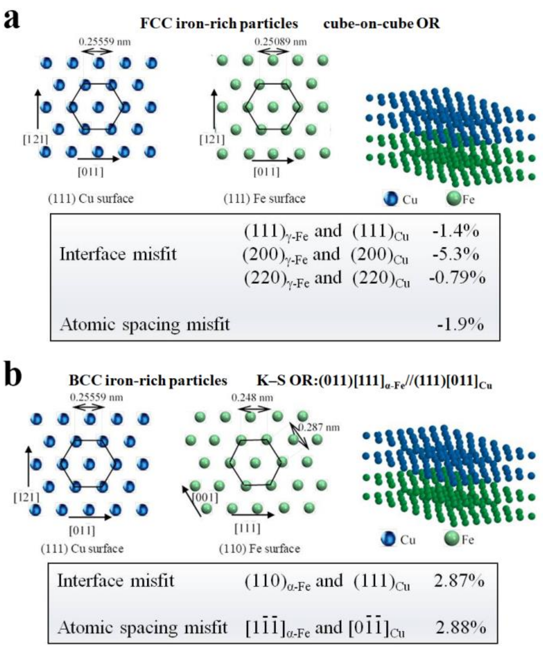
Two kinds of crystallographic structure [71], face-centered cubic (FCC) and body-centered cubic (BCC) lattice, are detected in iron-rich nanoparticles through Cs-corrected HAADF-STEM characterization, and atomic arrangement and matching at the Cu/Fe interface are schematically shown in Figure 12. It is noted that, when incident beam is along the [001]Cu zone axis, nanoparticle with FCC structure has cube-on-cube orientation relationship (OR) with Cu matrix. BCC iron-rich nanoparticles also exist in Cu matrix, which are identified as the pattern of BCC α-Fe under [111]α-Fe zone axis and OR between nanoparticle and matrix satisfied classic K–S OR. Mismatch degrees of all tested interface are very low, so we can conclude that there is a good coherent particle/matrix interface.

5. Optimizing Microstructure

Disparate from nano-precipitates produced during solid-state phase transformation, in-situ nanoparticles directly formed in the liquid melt, which greatly affect solidification process of matrix. Through various advanced characterization methods, in-situ nanoparticles are verified to possess conspicuous effects on grain refinement, inhibiting segregation and optimizing inclusions.

5.1. Grain Refinement

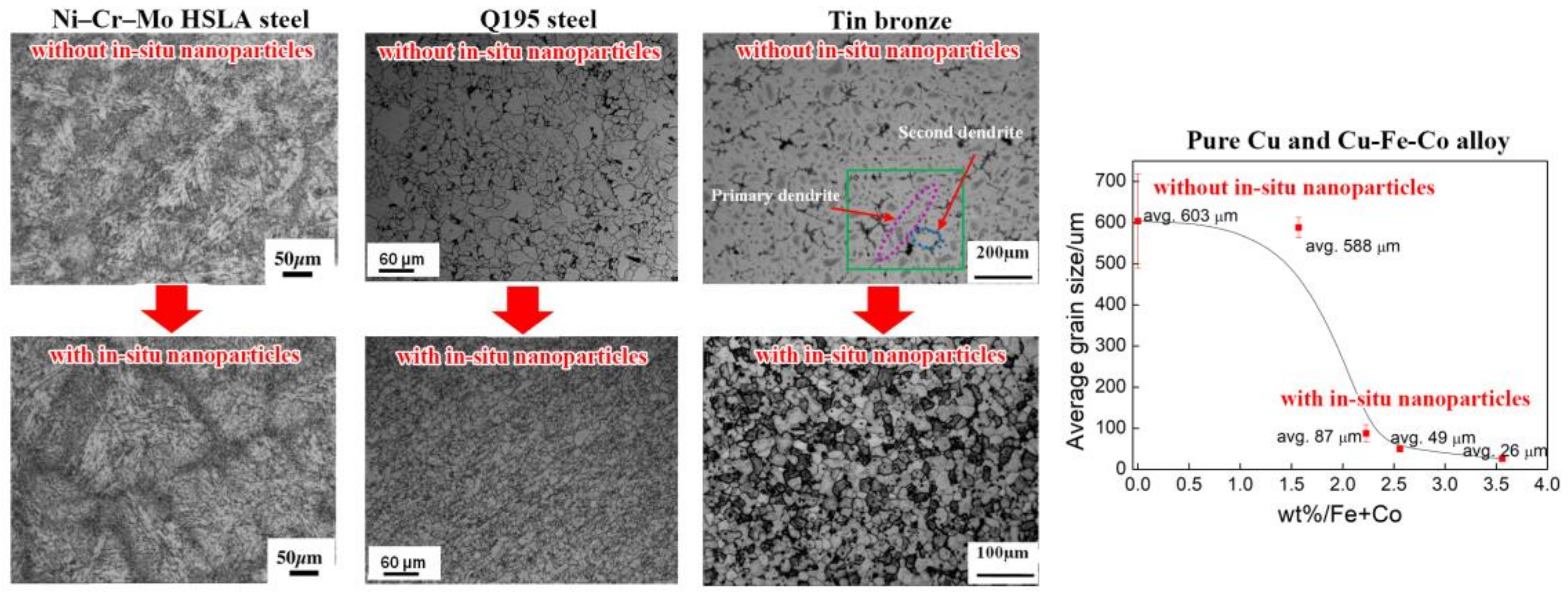
Strong grain refinement effect can emerge by heterogeneous nucleation caused by in-situ nanoparticles in our investigated alloys. Several optical images and statistic results of as-cast Ni-Cr-Mo HSLA steel [58], hot rolled Q195 steel [33], as-cast tin bronze [64], pure Cu and Cu-Fe-Co alloy [69] are shown in Figure 13. Typical dendritic structure with various orders of developed dendrite arms can be seen in conventional as-cast HSLA steel, while in nanoparticle strengthened HSLA steel the amount of dendrites is reduced obviously and equiaxed grains appear [58]. For hot rolled Q195 steels, in-situ nanoparticles can be retained after deformation and the grains are much smaller and distribute more uniformly compared with the base alloy [33]. In tin bronze alloys, the as-cast structure is significantly refined by iron-rich particles and columnar to equiaxed transition (CET) apparently appears [64], indicating that iron-rich nanoparticles precipitate earlier in Cu melt and subsequently induced heterogeneous nucleation during solidification to refine the matrix grains. Similar phenomenon happens in as-cast pure Cu and Cu-Fe-Co alloys, with Fe, Co addition typical CET occurs. In addition, the size of equiaxed grains decreases with the increase of Fe + Co content [69]. However, it should be noted that grain refinement effect is not enhanced indefinitely with increasing Fe/Co content. Chen et al. [71] found that only part of the nanoparticles can act as nucleation cores, and the latent heat released by recalescence [79,80] during the growth of prior nucleus will affect the undercooling degree, wherefore the nucleation of particles nearby are hindered. Interestingly, grains in tin bronze are much finer than that in Cu-Fe-Co cast alloys. This is because that the recalescence is weakened by growth restriction [81,82] through Sn, Zn elements in tin bronze, so heterogeneous nucleation can be effectively promoted.

5.2. Inhibiting Segregation

Deriving from tin, bronze alloys are always used in as-cast condition and segregation of δ phase at the grain boundary, which is caused by the solute redistribution of the Sn atoms during solidification process, greatly deteriorates the mechanical properties. Since it is very difficult to dissolve the phase through heat treatment, we can only control the segregation through casting process [83,84,85]. However, in our recent research, δ phase segregation was dramatically eliminated in as-cast Cu-10Sn-2Zn-1.5Fe-0.5Co alloy in contrast to virgin Cu-10Sn-2Zn tin bronze alloy, as shown in Figure 14a. Large amounts of iron-rich nanoparticles densely distributed in the copper play a significant important role in eliminating δ phase. It was reported that both Sn atoms and nanoparticles do irregular Brown motion in the melt [86], and Sn atoms will inevitably collide with nanoparticles which own relatively large surface area. Chen et al. [67] built the in-situ nanoparticle wall model [67] that densely distributed in-situ nanoparticles near solid/liquid interface can effectively absorb Sn atoms and prevent Sn atoms from escaping away (Black dashed lines: nanoparticle wall, seen in Figure 14c). 3DAP reconstruction result (Figure 14b) presents that Sn atoms aggregate at the surface of iron-rich nanoparticles, which is consistent with the in-situ nanoparticle wall model. Obviously, this method inhibits δ phase segregation by tailoring the migration rate of Sn atoms, which is totally different from solute trapping model in rapid solidification technique [87,88]. Hence, the in-situ nanoparticle wall model sheds light on a novel and easy way to eliminate segregation which is expected to be applied in reducing segregation of bulk metallic materials.

5.3. Optimizing Inclusions

It is well known that the inclusions usually form during solidification in steel. Generally, cracks can be generated by large-sized brittle inclusions and lead to failure. The shape, size and distribution of inclusions in steel have a great influence on the microstructure and mechanical performance [89,90]. To date, “oxides metallurgy technology” has been proposed to render oxide at micro/sub-micron scale in steel melt to be heterogeneous nucleus of sulfide, carbide or nitride, thus the inclusions can be well controlled [91]. Differently, in our investigation the in-situ nanoparticles give rise to distinct heterogeneous nucleation effect and significantly optimize inclusions. As shown in Figure 15a, with appropriate addition of Ti, the amount and the size of inclusions remarkable decrease due to the effect of Ti3O5 oxide [56]. In addition, many cubic inclusions (100–200 nm) originally located in the matrix change to circular ones (about 50 nm) and distribute in the intersections of grain boundary, indicating less possibility of crack generation. Notably, initial harmful inclusions can turn to serve as beneficial strengthening nano-scale phases. Furthermore, heterogeneous nucleation behavior can be proved by the composite precipitated particles existing in nanoparticle strengthened HSLA steel, as seen in Figure 15b. By TEM and EDS characterization, NbC and Ti3O5 are clearly identified, respectively [58]. In general, this brand new method is disparate from the traditional idea of removing large-size inclusions in the melt. Instead, it focuses on transforming inclusions to be favorable strengthening phases with refined size and optimized distribution, which can greatly improve the strength and toughness of steels simultaneously.

6. Improving Mechanical Property

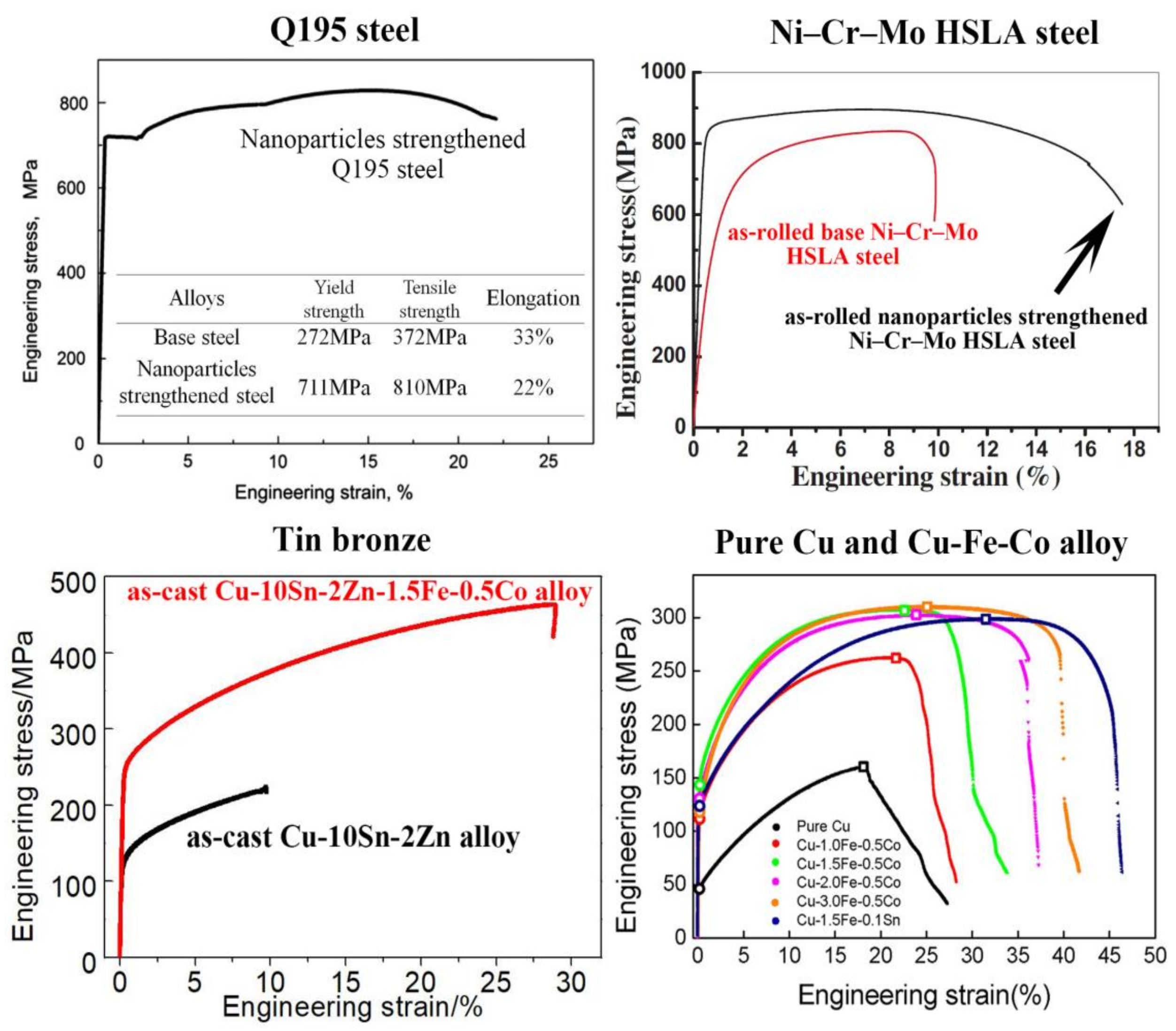
Experimentally, in-situ nanoparticle strengthening method is an effective strategy to enhance the strength of steel and Cu alloy without sacrificing plasticity, as seen in Figure 16. With appropriate microalloying elements and preparation technology, in-situ nanoparticles appear and the grains are refined. Therefore, the principle of strengthening is due to fine grains, precipitation strengthening and solution strengthening. It should be noted that the uniformly distributed Ti3O5, together with the optimized inclusion (seen in Figure 15a) pinning at the grain boundary in steels, will restrain the growth of grains and the movement of grain boundary according to Zener pinning theory, which contribute to strengthening effect [92,93,94].
Based on Orowan hardening mechanism, precipitation strengthening effect is mainly caused by the interaction between precipitates and dislocations during deformation [95,96,97]. While hindering the movement of dislocation, stress concentration occurs near the second phase which always leads to cracks initiation and rupture, indicating sacrificing the ductility. However, in-situ nanoparticle strengthening method can overcome this problem. Possessing coherent or semi-coherent interface of nanometer scale with the matrix, in-situ nanoparticles make contribution to strength and plasticity simultaneously. Dislocations are permitted to pass through the coherent matrix-particle interface, so stress concentration can be efficaciously relieved and considerable plastic strain turns to be possible, as seen in Section 2 and Figure 1. Specifically, it should be noted that the elimination of δ phase segregation is also advantageous to distinctly improve the ductility of tin bronze alloys.

7. Conclusions and Prospect

In this review, we proposed the concept of in-situ nanoparticle strengthening method and summarized recent related advances in steels and Cu alloys. With combination of appropriate elements addition, thermodynamic calculation and preparation techniques, myriads of in-situ nanoparticles can spontaneously form in the molten metal during conventional solidification process, possessing good stability and excellent coherency with the matrix. These nanoparticles played important roles in grain refinement, inhibiting segregation, optimizing inclusions and strengthening. Resultantly, not only superior microstructure but also remarkable comprehensive mechanical response can be obtained. Therefore, this brand new method provides a guideline for engineering microstructure to fabricate simultaneously strong and ductile bulk metals.
However, it should be mentioned that the strength of in-situ nanoparticle strengthened materials is far from the limit. The composition and crystallographic structure of in-situ nanoparticles need to be further optimized through systematic scientific calculation and microstructure characterization. Moreover, the emphasis of our research is about as-cast ingots, and effects of subsequent processing on microstructure and property are still lacking. With the combining of advanced plastic processing and heat treatment technology, it is expected that in-situ nanoparticle strengthened metallic structural materials will play a role in industrial mass production in the future.

Author Contributions

S.P. wrote the manuscript; S.P., M.Y. and Y.C. conducted a literature survey; Z.W. and X.C. organized the structure of the review article; K.C., X.Z. and Z.W. discussed and commented on the manuscript.

Funding

This research received no external funding.

Acknowledgments

The author, S.P., would specifically like to highlight the ongoing and unwavering support and love from his wife (Vicky Wang) during the paper writing process.

Conflicts of Interest

The authors declare no conflict of interest.

References

  1. Agrawal, A.; Dube, R. Methods of fabricating Cu-Al-Ni shape memory alloys. J. Alloys Compd. 2018, 750, 235–247. [Google Scholar] [CrossRef]
  2. Luo, X.; Chen, X.; Wang, T.; Pan, S.; Wang, Z. Effect of morphologies of martensite–austenite constituents on impact toughness in intercritically reheated coarse-grained heat-affected zone of HSLA steel. Mater. Sci. Eng. A 2018, 710, 192–199. [Google Scholar] [CrossRef]
  3. Pan, S.; Huang, X.; Xin, Y.; Huang, G.; Li, Q.; Tan, C.; Liu, Q. The effect of hot rolling regime on texture and mechanical properties of an as-cast Mg–2Zn–2Gd plate. Mater. Sci. Eng. A 2018, 731, 288–295. [Google Scholar] [CrossRef]
  4. Pan, S.; Xin, Y.; Huang, G.; Li, Q.; Guo, F.; Liu, Q. Tailoring the texture and mechanical anisotropy of a Mg–2Zn–2Gd plate by varying the rolling path. Mater. Sci. Eng. A 2016, 653, 93–98. [Google Scholar] [CrossRef]
  5. Dursun, T.; Soutis, C. Recent developments in advanced aircraft aluminium alloys. Mater. Des. 2014, 56, 862–871. [Google Scholar] [CrossRef]
  6. Lu, K. The future of metals. Science 2010, 328, 319–320. [Google Scholar] [CrossRef]
  7. Hall, E. Deformation and Ageing of Mild Steel: III Discussion of Results. Proc. Phys. Soc. Lond. Ser. B 1951, 64, 747–753. [Google Scholar] [CrossRef]
  8. Petch, N.J. The cleavage of polycrystals. J. Iron Steel Inst. 1953, 174, 25–28. [Google Scholar]
  9. Huang, Y.; Langdon, T.G. Advances in ultrafine-grained materials. Mater. Today 2013, 16, 85–93. [Google Scholar] [CrossRef]
  10. Kang, Z.; Zhou, L.; Zhang, J. Achieving high strain rate superplasticity in Mg–Y–Nd–Zr alloy processed by homogenization treatment and equal channel angular pressing. Mater. Sci. Eng. A 2015, 633, 59–62. [Google Scholar] [CrossRef]
  11. Shin, D.H.; Park, K.T. Ultrafine grained steels processed by equal channel angular pressing. Mater. Sci. Eng. A 2005, 410–411, 299–302. [Google Scholar] [CrossRef]
  12. Kawasaki, M.; Beyerlein, I.J.; Vogel, S.C.; Langdon, T.G. Characterization of creep properties and creep textures in pure aluminum processed by equal-channel angular pressing. Acta Mater. 2008, 56, 2307–2317. [Google Scholar] [CrossRef]
  13. Figueiredo, R.B.; Kawasaki, M.; Xu, C.; Langdon, T.G. Achieving superplastic behavior in fcc and hcp metals processed by equal-channel angular pressing. Mater. Sci. Eng. A 2008, 493, 104–110. [Google Scholar] [CrossRef]
  14. Figueiredo, R.B.; Langdon, T.G. Strategies for achieving high strain rate superplasticity in magnesium alloys processed by equal-channel angular pressing. Scr. Mater. 2009, 61, 84–87. [Google Scholar] [CrossRef]
  15. Cho, T.S.; Lee, H.J.; Ahn, B.; Kawasaki, M.; Langdon, T.G. Microstructural evolution and mechanical properties in a Zn–Al eutectoid alloy processed by high-pressure torsion. Acta Mater. 2014, 72, 67–79. [Google Scholar] [CrossRef]
  16. Sakai, G.; Horita, Z.; Langdon, T.G. Grain refinement and superplasticity in an aluminum alloy processed by highpressure torsion.pdf. Mater. Sci. Eng. A 2005, 393, 344–351. [Google Scholar] [CrossRef]
  17. García-Infanta, J.M.; Zhilyaev, A.P.; Sharafutdinov, A.; Ruano, O.A.; Carreño, F. An evidence of high strain rate superplasticity at intermediate homologous temperatures in an Al–Zn–Mg–Cu alloy processed by high-pressure torsion. J. Alloys Compd. 2009, 473, 163–166. [Google Scholar] [CrossRef]
  18. Gutierrez-Urrutia, I.; Muñoz-Morris, M.A.; Morris, D.G. Contribution of microstructural parameters to strengthening in an ultrafine-grained Al–7% Si alloy processed by severe deformation. Acta Mater. 2007, 55, 1319–1330. [Google Scholar] [CrossRef] [Green Version]
  19. Mondal, D.P.; Jha, N.; Gull, B.; Das, S.; Badkul, A. Microarchitecture and compressive deformation behaviour of Al-alloy (LM13)–cenosphere hybrid Al-foam prepared using CaCO3 as foaming agent. Mater. Sci. Eng. A 2013, 560, 601–610. [Google Scholar] [CrossRef]
  20. Zhu, S.M.; Mordike, B.L.; Nie, J.F. Creep properties of a Mg–Al–Ca alloy produced by different casting technologies. Mater. Sci. Eng. A 2008, 483–484, 583–586. [Google Scholar] [CrossRef]
  21. Kumar, A.; Torbet, C.J.; Pollock, T.M.; Wayne, J.J. In situ characterization of fatigue damage evolution in a cast Al alloy via nonlinear ultrasonic measurements. Acta Mater. 2010, 58, 2143–2154. [Google Scholar] [CrossRef]
  22. Sharma, M.M. Microstructural and mechanical characterization of various modified 7XXX series spray formed alloys. Mater. Charact. 2008, 59, 91–99. [Google Scholar] [CrossRef]
  23. Li, H.; Cao, F.; Guo, S.; Ning, Z.; Liu, Z.; Jia, Y.; Scudino, S.; Gemming, T.; Sun, J. Microstructures and properties evolution of spray-deposited Al-Zn-Mg-Cu-Zr alloys with scandium addition. J. Alloys Compd. 2017, 691, 482–488. [Google Scholar] [CrossRef]
  24. Xu, J.Q.; Chen, L.Y.; Choi, H.; Li, X.C. Theoretical study and pathways for nanoparticle capture during solidification of metal melt. J. Phys. Condens. Matter 2012, 24, 255304. [Google Scholar] [CrossRef] [PubMed]
  25. Groza, J.R.; Gibeling, J.C. Principles of particles election for dispersion-strengthened copper. Mater. Sci. Eng. Part A 1993, A171, 115–125. [Google Scholar] [CrossRef]
  26. Arakawa, K.; Mada, T.; Takahashi, J.; Todo, M.; Ooka, S. Effect of rubber particle size on the impact tensile fracture behavior of MBS resin with a bimodal particle size distribution. J. Mater. Sci. 2007, 42, 8700–8706. [Google Scholar] [CrossRef]
  27. Lee, J.; Jung, J.; Lee, E.; Park, W.; Ahn, S.; Kim, N. Microstructure and properties of titanium boride dispersed Cu alloys fabricated by spray forming. Mater. Sci. Eng. A 2000, 277, 274–283. [Google Scholar] [CrossRef]
  28. Zhao, Y.; Zhang, S.; Chen, G.; Cheng, X.; Wang, C. In situ (Al2O3 + Al3Zr)np/Al nanocomposites synthesized by magneto-chemical melt reaction. Compos. Sci. Technol. 2008, 68, 1463–1470. [Google Scholar] [CrossRef]
  29. Kang, Y.; Chan, S. Tensile properties of nanometric Al2O3 particulate-reinforced aluminum matrix composites. Chem. Phys. 2004, 85, 438–443. [Google Scholar] [CrossRef]
  30. Maik, T.; Beffort, O.; Kleiner, S.; Vogt, U. Aluminum matrix composites based on preceramic-polymer-bonded SiC preforms. Compos. Sci. Technol. 2007, 67, 2377–2383. [Google Scholar]
  31. Miller, M.; Hoelzer, D.; Kenik, E.; Russell, K. Nanometer scale precipitation in ferritic MA/ODS alloy MA957. J. Nucl. Mater. 2004, 329–333, 338–341. [Google Scholar] [CrossRef]
  32. Yang, X.; Cheng, G.; Wang, M.; Zhao, P. Precipitation and growth of titanium nitride during solidification of clean steel. J. Univ. Sci. Technol. B 2003, 10, 24–26. [Google Scholar]
  33. Tang, H.; Chen, X.; Chen, M.; Zuo, L.; Hou, B.; Wang, Z. Microstructure and mechanical property of in-situ nano-particle strengthened ferritic steel by novel internal oxidation. Mater. Sci. Eng. A 2014, 609, 293–299. [Google Scholar] [CrossRef]
  34. Callister, W.D. Materials Science and Engineering: An Introduction; John Wiley & Sons: Hoboken, NJ, USA, 2007. [Google Scholar]
  35. Rashid, M. High-Strength, Low-Alloy Steels. Science 1980, 208, 862–869. [Google Scholar] [CrossRef]
  36. Nagorka, M.S.; Levi, C.G.; Lucas, G.E.; Ridder, S.D. The potential of rapid solidification in oxide-dispersion-strengthened. Mater. Sci. Eng. A 1991, 104, 277–289. [Google Scholar] [CrossRef]
  37. Lu, K.; Lu, L.; Suresh, S. Strengthening materials by engineering coherent internal boundaries at the nanoscale. Science 2009, 324, 349–352. [Google Scholar] [CrossRef] [PubMed]
  38. Shi, G.; Chen, X.; Jiang, H.; Wang, Z.; Tang, H.; Fan, Y. Strengthening mechanisms of Fe nanoparticles for single crystal Cu–Fe alloy. Mater. Sci. Eng. A 2015, 636, 43–47. [Google Scholar] [CrossRef]
  39. Takata, N.; Ohtake, Y.; Kita, K.; Kitagawa, K.; Tsuji, N. Increasing the ductility of ultrafine-grained copper alloy by introducing fine precipitates. Scr. Mater. 2009, 60, 590–593. [Google Scholar] [CrossRef]
  40. Wang, Z.; Wang, X.; Wang, Q.; Shih, I.; Xu, J.J. Fabrication of a nanocomposite from in situ iron nanoparticle reinforced copper alloy. Nanotechnology 2009, 20, 075605. [Google Scholar] [CrossRef] [PubMed]
  41. Chen, X.; Wang, Z.; Ding, D.; Tang, H.; Qiu, L.; Luo, X.; Shi, G. Strengthening and toughening strategies for tin bronze alloy through fabricating in-situ nanostructured grains. Mater. Des. 2015, 66, 60–66. [Google Scholar] [CrossRef]
  42. Jiang, S.; Wang, H.; Wu, Y.; Liu, X.; Chen, H.; Yao, M.; Gault, B.; Ponge, D.; Raabe, D.; Hirata, A.; et al. Ultrastrong steel via minimal lattice misfit and high-density nanoprecipitation. Nature 2017, 544, 460–464. [Google Scholar] [CrossRef] [PubMed]
  43. Meslet, A.; Aldo, M.; Woods, R.; Srivatsan, T.S. Influence of heat treatment on tensile response of an oxide dispersion strengthened copper-main. J Alloys Compd. 1999, 290, 290–297. [Google Scholar] [CrossRef]
  44. Vencl, A.; Rajkovic, V.; Zivic, F.; Mitrović, S.; Cvijović-Alagić, I.; Jovanovic, M.T. The effect of processing techniques on microstructural and tribological properties of copper-based alloys. Appl. Surf. Sci. 2013, 280, 646–654. [Google Scholar] [CrossRef]
  45. Naser, J.; Rieheman, W.; Ferkel, H. Dispersion hardening of metals by nanoscaled ceramic powders. Mater. Sci. Eng. A 1997, 234–236, 467–469. [Google Scholar] [CrossRef]
  46. Fathy, A.; Shehata, F.; Abdelhameed, M.; Elmahdy, M. Compressive and wear resistance of nanometric alumina reinforced copper matrix composites. Mater. Des. 2012, 36, 100–107. [Google Scholar] [CrossRef]
  47. Schneibel, J.H.; Liu, C.T.; Hoelzer, D.T.; Mills, M.J.; Sarosi, P.; Hayashi, T.; Wendt, U.; Heyse, H. Development of porosity in an oxide dispersion-strengthened ferritic alloy containing nanoscale oxide particles. Scr. Mater. 2007, 57, 1040–1043. [Google Scholar] [CrossRef]
  48. Ma, Z.Y.; Li, J.H.; Luo, M.; Ning, X.G.; Lu, Y.X.; Bi, J.Y.; Zhang, Z. In-situ formed Al2O3 and TiB2 particulates mixture-reinforced aluminum composite. Scr. Metall. Mater. 1994, 31, 635–639. [Google Scholar] [CrossRef]
  49. Lu, W.; Zhang, D.; Zhang, X.; Wu, R.; Sakata, T.; Mori, H. HREM study of TiB-Ti interfaces in a TiB-TiC in situ composite-main. Scr. Mater. 2001, 44, 1069–1075. [Google Scholar] [CrossRef]
  50. Kuruvilla, A.K.; Prasad, K.S.; Bhanuprasad, V.V.; Mahajan, Y.R. Microstructure-property correlation in AlTiB2 (XD) composites. Scr. Metall. Mater. 1990, 24, 873–878. [Google Scholar] [CrossRef]
  51. Gleiter, H. Nanostructured materials: Basic concepts and microstructure. Acta Mater. 2000, 48, 1–29. [Google Scholar] [CrossRef]
  52. Zuo, L.; Wei, Z.; Ni, R.; Ma, B.; Wang, Z. Effect of Aging Temperature on the Microstructure and Mechanical Properties of 1000 MPa Grade Low Carbon Bainitic Steel. Appl. Mech. Mater. 2012, 152–154, 376–380. [Google Scholar] [CrossRef]
  53. Zuo, L.; Qiu, L.; Hou, B.; Chen, X.; Chen, M.; Wang, Z. Study of Nano-precipitate in high strength low carbon steel during tempering by TEM. Appl. Mech. Mater. 2013, 327, 123–127. [Google Scholar] [CrossRef]
  54. Wei, Z.; Zuo, L.; Ma, B.; Zhang, L.; Zhang, H.; Wang, Z. Effect of Heat Treatment on Microstructure and Mechanical Properties of 800 MPa Grade Ultra Low Carbon Bainite Steel. Adv. Mater. Res. 2011, 415–417, 943–946. [Google Scholar] [CrossRef]
  55. Niu, Y.; Tang, H.; Wang, Y.; Chen, X.; Wang, Z.; Chen, K.; Wu, Y.; Liu, X. Effect of In Situ Nano-Particles on the Microstructure and Mechanical Properties of Ferritic Steel. Steel Res. Int. 2016, 87, 1389–1394. [Google Scholar] [CrossRef]
  56. Tang, H.; Chen, X.; Luo, X.; Chen, M.; Wang, Z.; Zuo, L. Heterogeneous nucleation effect of in situ nanoparticles on the metal–matrix microstructure. Mater. Lett. 2014, 137, 455–459. [Google Scholar] [CrossRef]
  57. Tang, H.; Chen, X.; Niu, Y.; Luo, X.; Wang, Z.; Chen, M.; Shi, G. Thermal stability characteristics of in situ nano-particles formed in metal melt. Mater. Lett. 2016, 162, 261–264. [Google Scholar] [CrossRef]
  58. Chen, X.; Qiu, L.; Tang, H.; Luo, X.; Zuo, L.; Wang, Z.; Wang, Y. Effect of nanoparticles formed in liquid melt on microstructure and mechanical property of high strength naval steel. J. Mater. Process. Technol. 2015, 222, 224–233. [Google Scholar] [CrossRef]
  59. Tang, H. Microstructure and Properties of in Situ Nano Particle Reinforced High Strength and Toughness Steel. Ph.D. Thesis, University of Science and Technology Beijing, Beijing, China, 2016. [Google Scholar]
  60. Booth-Morrison, C.; Dunand, D.; Seidman, D. Coarsening resistance at 400°C of precipitation-strengthened Al–Zr–Sc–Er alloys. Acta. Mater. 2011, 59, 7029–7042. [Google Scholar] [CrossRef]
  61. Knipling, K.; Karnesky, R.; Lee, C.; Dunand, D.; Seidman, D. Precipitation evolution in Al–0.1Sc, Al–0.1Zr and Al–0.1Sc–0.1Zr (at.%) alloys during isochronal aging. Acta Mater. 2010, 58, 5184–5195. [Google Scholar] [CrossRef]
  62. Shi, G.; Chen, X.; Jiang, H.; Zhao, Z.; Wang, Z.; Wang, T.; Luo, X. Dendrite remelting of petal-shaped iron-rich nanoparticles in Cu-2wt% Fe alloy at the nanoscale. Mater. Lett. 2016, 166, 231–234. [Google Scholar] [CrossRef]
  63. Chen, K.; Chen, X.; Ding, D.; Shi, G.; Wang, Z. Heterogeneous nucleation effect of in situ iron-rich nanoparticles on grain refinement of copper alloy. Mater. Lett. 2016, 168, 188–191. [Google Scholar] [CrossRef]
  64. Chen, K.; Chen, X.; Ding, D.; Shi, G.; Wang, Z. Formation mechanism of in-situ nanostructured grain in cast Cu–10Sn–2Zn–1.5Fe–0.5Co (wt.%) alloy. Mater. Des. 2016, 94, 338–344. [Google Scholar] [CrossRef]
  65. Chen, K.; Tang, H.; Chen, X.; Ding, D.; Shi, G.; Wang, Z. Morphological instability of spherical nano iron-rich crystal in copper melt. Mater. Lett. 2016, 172, 125–127. [Google Scholar] [CrossRef]
  66. Chen, K.; Chen, X.; Ding, D.; Shi, G.; Wang, Z. Crystallographic features of iron-rich nanoparticles in cast Cu–10Sn–2Zn–1.5Fe–0.5Co alloy. Mater. Charact. 2016, 113, 34–42. [Google Scholar] [CrossRef]
  67. Chen, K.; Chen, X.; Ding, D.; Wang, Z. Effect of in-situ nanoparticle wall on inhibiting segregation of tin bronze alloy. Mater. Lett. 2016, 175, 148–151. [Google Scholar] [CrossRef]
  68. Chen, K.; Pan, S.; Zhu, Y.; Cheng, Y.; Chen, X.; Wang, Z. In situ observations of crack propagation in as-cast Cu-1.5Fe-0.5Co (wt%) alloy. Mater. Sci. Eng. A 2017, 706, 211–216. [Google Scholar] [CrossRef]
  69. Chen, K.; Chen, X.; Wang, Z.; Mao, H.; Rolf, S. Optimization of deformation properties in as-cast copper by microstructural engineering. Part I. microstructure. J. Alloys Compd. 2018, 763, 592–605. [Google Scholar] [CrossRef]
  70. Chen, K.X.; Korzhavyi, P.; Demange, G.; Zapolsky, H.; Patte, R.; Boisse, J.; Wang, Z. Morphological instability of iron-rich precipitates in Cu Fe Co alloys. Acta Mater. 2019, 163, 55–67. [Google Scholar] [CrossRef]
  71. Chen, K. Microstructure and Deformation Properties of Nanoparticle-Fine Grain (NPFG) Synergistically Reinforced Copper Alloys. Ph.D. Thesis, University of Science and Technology Beijing, Beijing, China, 2018. [Google Scholar]
  72. Zhai, W.; Wang, W.; Geng, D.; Wei, B. A DSC analysis of thermodynamic properties and solidification characteristics for binary Cu–Sn alloys. Acta Mater. 2012, 60, 6518–6527. [Google Scholar] [CrossRef]
  73. Yu, Y.N. Fundamentals of Material Science; Higher Education Press: Beijing, China, 2006. [Google Scholar]
  74. Das, S.K.; Chatterjee, S.; Tarafder, S. Tensile fracture behaviour of microstructurally engineered Cu bearing high strength low alloy steel. Mater. Sci. Technol. 2013, 22, 1409–1414. [Google Scholar] [CrossRef]
  75. Chairuangsri, T.; Edmonds, D.V. The precipitation of copper in abnormal ferrite and pearlite in hyper-eutectoid steels. Acta Mater. 2000, 48, 3931–3949. [Google Scholar] [CrossRef]
  76. Pande, C.S.; Ashraf Imam, M.; Vold, C.L.; Dantsker, E.; Rath, B.B. Study of Precipitation Kinetics in High Strength Low Carbon Ferrous Alloys. Key Eng. Mater. 1993, 84, 145–174. [Google Scholar] [CrossRef]
  77. Kotan, H.; Darling, K.A.; Saber, M.; Scattergood, R.O.; Koch, C.C. Thermal stability and mechanical properties of nanocrystalline Fe–Ni–Zr alloys prepared by mechanical alloying. J. Mater. Sci. 2013, 48, 8402–8411. [Google Scholar] [CrossRef]
  78. Yong, Q.L. Secondary Phases in Steels; Metallurgical Industry Press: Beijing, China, 2006. [Google Scholar]
  79. Li, H.; Wang, Y.; Fan, Z. Mechanisms of enhanced heterogeneous nucleation during solidification in binary Al–Mg alloys. Acta Mater. 2012, 60, 1528–1537. [Google Scholar] [CrossRef] [Green Version]
  80. Men, H.; Fan, Z. Effects of solute content on grain refinement in an isothermal melt. Acta Mater. 2011, 59, 2704–2712. [Google Scholar] [CrossRef] [Green Version]
  81. Maxwell, I.; Hellawell, A. An analysis of the peritectic reaction with particular reference to Al-Ti alloys. Acta Metall. 1975, 23, 901–909. [Google Scholar] [CrossRef]
  82. Greer, A.; Bunn, A.; Tronche, A.; Evans, P.; Bristow, D. Modelling of inoculation of metallic melts: application to grain refinement of Aluminium by Al-Ti-B. Acta Mater. 2000, 48, 2823–2835. [Google Scholar] [CrossRef]
  83. Kumoto, E.; Alhadeff, R.; Martorano, M. Microsegregation and dendrite arm coarsening in tin bronze. Mater. Sci. Technol. 2013, 18, 1001–1006. [Google Scholar] [CrossRef]
  84. Park, J.; Park, C.; Lee, K. Implication of peritectic composition in historical high-tin bronze metallurgy. Mater. Charact. 2009, 60, 1268–1275. [Google Scholar] [CrossRef]
  85. Türk, A.; Durman, M.; Kayali, E. The effect of manganese on the microstructure and mechanical. J. Mater. Process. Technol. 2007, 42, 8298–8305. [Google Scholar] [CrossRef]
  86. Ring, E.; deJonge, N. Video-frequency scanning transmission electron microscopy of moving gold nanoparticles in liquid. Micron 2012, 43, 1078–1084. [Google Scholar] [CrossRef] [PubMed]
  87. Evans, P.; Greer, A. Modelling of crystal growth and solute redistribution during rapid solidification. Mater. Sci. Eng. A 1988, 98, 357–361. [Google Scholar] [CrossRef]
  88. Aziz, M. Model for solute redistribution during rapid solidification. J. Appl. Phys. 1982, 53, 1158–1168. [Google Scholar] [CrossRef] [Green Version]
  89. Li, Y.; Zhu, F.; Cui, F. Analysis of Forming Mechanism of Lamination Defect of Steel Plate. J. Northeast. Univ. Nat. Sci. 2007, 28, 1002–1005. [Google Scholar] [CrossRef]
  90. Domizzi, G.; Anteri, G.; Ovejero-Garcia, J. Influence of sulphur content and inclusion distribution on the hydrogen induced blister cracking in pressure vessel and pipeline steels. Corros. Sci. 2001, 43, 325–339. [Google Scholar] [CrossRef]
  91. Pickering, F. Physical Metallurgy and the Design of Steels; Applied Science Publication Limited: London, UK, 1978. [Google Scholar]
  92. Nes, E.; Ryum, N.; Hunderi, O. On the Zener drag. Acta Mater. 1985, 33, 11–22. [Google Scholar] [CrossRef]
  93. Mecking, H.; Kocks, U.F. Kinetics of flow and strain-hardening. Acta Mater. 1981, 29, 1865–1875. [Google Scholar] [CrossRef]
  94. Mao, X.; Huo, X.; Sun, X.; Chai, Y. Strengthening mechanisms of a new 700MPa hot rolled Ti-microalloyed steel produced by compact strip production. J. Mater. Process. Technol. 2010, 210, 1660–1666. [Google Scholar] [CrossRef]
  95. Callister, W. Materials Science and Engineering: An Introduction; Wiley: New York, NY, USA, 2007. [Google Scholar]
  96. Reed-Hill, R. Physical Metallurgy Principle, 2nd ed.; PWS Kent: Whitstable, UK, 1973. [Google Scholar]
  97. Orowan, E. Dislocations in Metals; AIME Publication: New York, NY, USA, 1954. [Google Scholar]
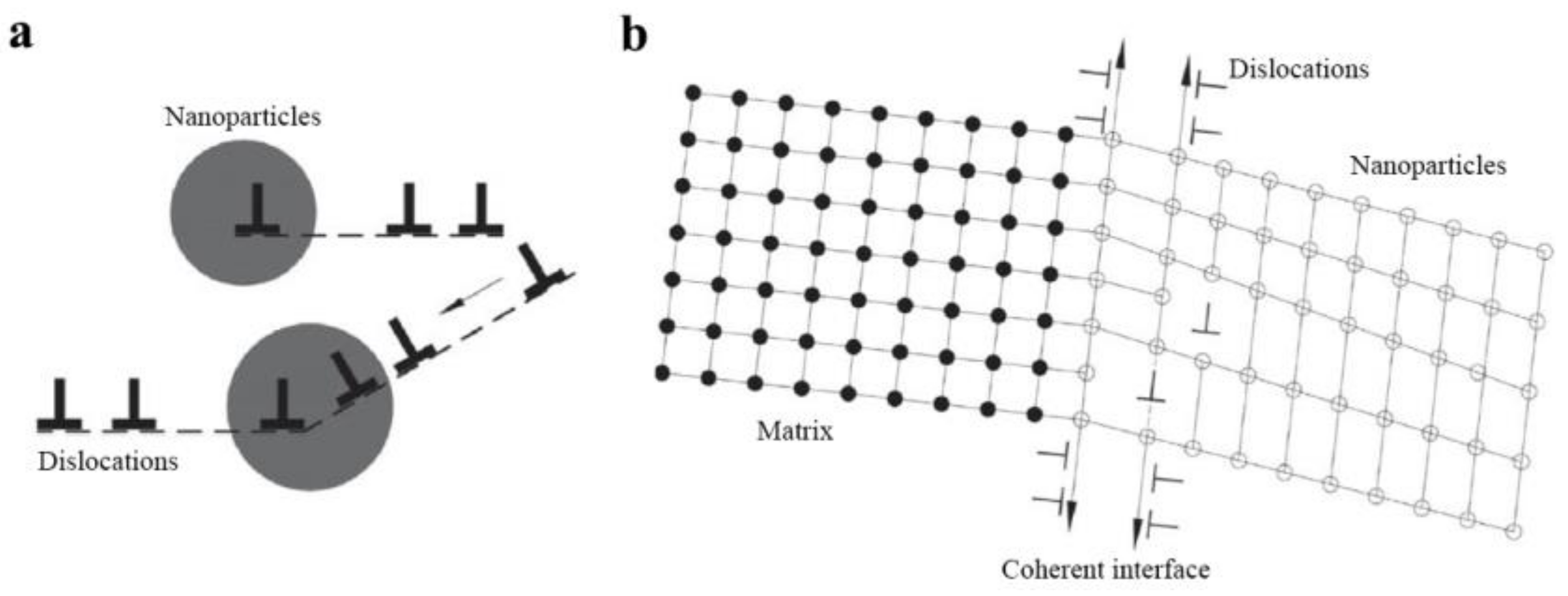
Figure 1. Strengthening mechanisms of the in-situ nanoparticles being coherent to the matrix [38]. (a) when slipping dislocations meet these nano-scale coherent interfaces, they will slip along the coherent interface and enter into the nanoparticles (Some stay inside the nanoparticles, while others pass through the interface and continue slipping); (b) schematical diagram of dislocations movement around the coherent interface.
Applsci 08 02479 g001
Figure 2. (a) The precipitated phase composition diagram and (b) its local magnification of Ti microalloying steel; (c) the elemental composition of liquid phase [59].
Applsci 08 02479 g002
Figure 3. (a) The solid solubility of Ti, O and (b) molar fraction of precipitates in Ti0.05%-O0.002% series high-strength steel change as a function of temperature [59].
Applsci 08 02479 g003
Figure 4. Schematic diagram of the processing method for the formation of nanoparticles in melt through a combination of multipoint dispersion supply processing (unique addition method of Ti wires) and electromagnetic stirring (strong convection stirring) [33].
Applsci 08 02479 g004
Figure 5. (a) The equilibrium mole fraction of phases calculated using the TCCU2 database in Thermo-Calc package as a function of temperature for Cu-10Sn-2Zn-1.5Fe-0.5Co alloy; (b) is an enlarged view of the dotted box in (a) [71].
Applsci 08 02479 g005
Figure 6. DSC curve of melted Cu-10Sn-2Zn-1.5Fe-0.5Co alloy at cooling rate of 20 K/min, with the upper-left enlarged image of area 1. [64]. The exothermic phenomenon during the cooling process was recorded and details can be seen clearly in the upper-left inset.
Applsci 08 02479 g006
Figure 7. NPFG structure in-situ formed in cast Cu-10Sn-2Zn-1.5Fe-0.5Co (wt. %) alloy [64]. Large amounts of iron-rich particles in-situ form in the melt at first, which can absorb Cu atoms in the melt. During the solidification process, a small part of nanoparticles can serve as nucleation cores and most particles are captured by the solid/liquid interface. Resultantly, typical NPFG structure is observed in as-cast ingots.
Applsci 08 02479 g007
Figure 8. TEM images and corresponding selected area diffraction pattern (SADP) of in-situ nanoparticles in as-cast Q235 steel [59], Q195 steel [33], Ni-Cr-Mo HSLA steel [58] and Ni-Cr-Mo-V-Nb-Ti ship steel [59].
Applsci 08 02479 g008
Figure 9. HRTEM micrograph of the nanoparticles in Ni-Cr-Mo-V-Nb-Ti ship steel at (a) as-cast and (b) 700 °C tempered state, respectively (Demarcate analysis of the SADP are shown in the insets) [57].
Applsci 08 02479 g009
Figure 10. Bright field image (TEM) of the Ni-Cr-Mo-V-Nb-Ti ship steel in different states and average diameter and volume fraction of the nano-particles in different states [57,59].
Applsci 08 02479 g010
Figure 11. SEM and TEM micrographs of in-situ nanoparticles in as-cast Cu-1.5Fe-0.5Co alloy [69], Cu-10Sn-2Zn-1.5Fe-0.5Co alloy [63,67], Cu-1Fe alloy [38] and Cu-3Sn-8Zn-6Pb-1Fe alloy [40].
Applsci 08 02479 g011
Figure 12. Schematic illustration of atomic arrangement and matching at interface between (a) FCC iron-rich particles and Cu matrix, (b) BCC iron-rich particles and Cu matrix based on TEM characterization results [71].
Applsci 08 02479 g012
Figure 13. Grain refinement effect caused by in-situ nanoparticles in Ni-Cr-Mo HSLA steel [58], Q195 steel [33], Tin bronze [64], pure Cu and Cu-Fe-Co alloy [69].
Applsci 08 02479 g013
Figure 14. (a) SEM micrographs showing microstructure of cast Cu-10Zn-2Sn and Cu-10Sn-2Zn-1.5Fe-0.5Co alloys, (b) a 3D atom map reconstruction of an iron-rich nanoparticle and (c) in-situ nanoparticle wall model: densely distributed nanoparticles near solid/liquid interface inhibit Sn atom segregation [67].
Applsci 08 02479 g014
Figure 15. (a) TEM micrograph and EDS result of inclusions in the investigated plain carbon steel with and without in-situ nanoparticles [56], (b) TEM and EDS analysis of the composite nano-precipitated phase in Ni-Cr-Mo HSLA steel [58].
Applsci 08 02479 g015
Figure 16. Engineering stress–strain curves of in-situ nanoparticles strengthened alloys compared with each corresponding virgin alloy [33,58,64,69].
Applsci 08 02479 g016
Table 1. Composition of iron-rich phase in Cu-10Sn-2Zn-1.5Fe-0.5Co alloy at different temperatures [71].
Temperature/KPhasePhase Compositions/wt. %
FeCoCuZnSn
1300FCC_L1268.38923.6717.7820.0890.070
1200FCC_L1272.80221.5755.3980.1410.084
1000BCC_B276.11323.5451.2580.1960.023
600BCC_B274.95324.9750.0670.0047.17 × 10−6
298/62.0117.0319.690.320.94
Table 2. Statistics results of number density Nv, mean radius rmean (or radius range rr), volume fraction f of spherical and petal-like nanoparticles in Cu alloys.
AlloysMorphology 1Nv
(m−3)
rmean/rr
(nm)
f
(vol. %)
Reference
Cu-1.0Fe-0.5Cospherical1.4 × 102021.80.6[69,71]
Cu-1.5Fe-0.5Cospherical1.1 × 102028.21.0
Cu-2.0Fe-0.5Cospherical + petal-like5.0 × 101944.31.8
Cu-3.0Fe-0.5Cospherical + petal-like2.7 × 101959.12.3
Cu-1.5Fe-0.1Snspherical5.0 × 101927.70.4
Cu-10Sn-2Zn-1.5Fespherical + petal-like-61.6[41]
Cu-10Sn-2Zn-1.5Fe-0.5Cospherical + petal-like2.01 × 102420–40-[64]
Cu-3Sn-8Zn-6Pb-1Fespherical-2–20-[40]
Cu-1Fespherical + petal-like-5–50-[38]
1 Only the statistic results of spherical and petal-like nanoparticles are illustrated.