Residual Properties Analysis of Steel Reinforced Recycled Aggregate Concrete Components after Exposure to Elevated Temperature

Abstract
:1. Introduction
2. Experimental Work
2.1. Test Materials
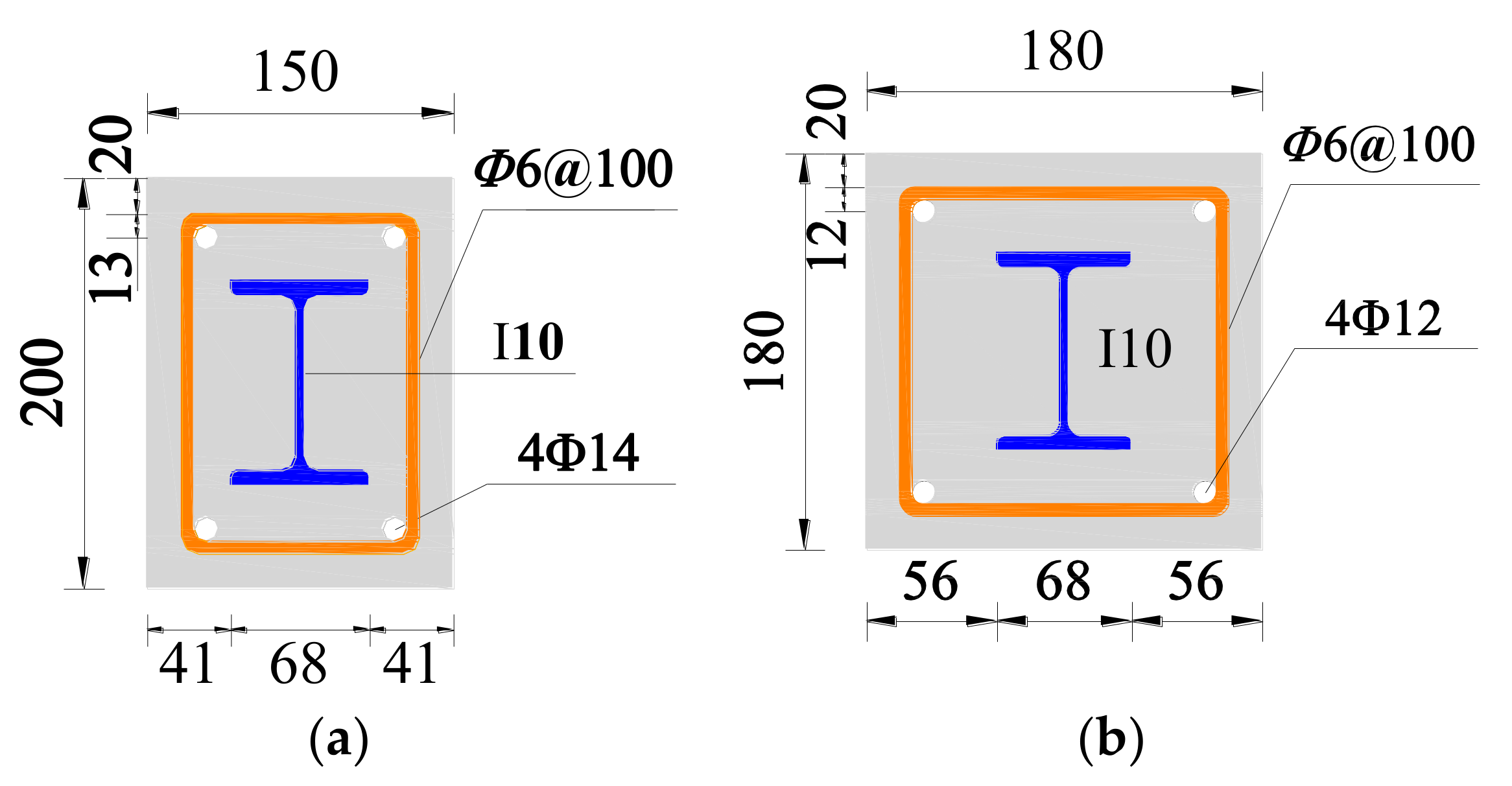
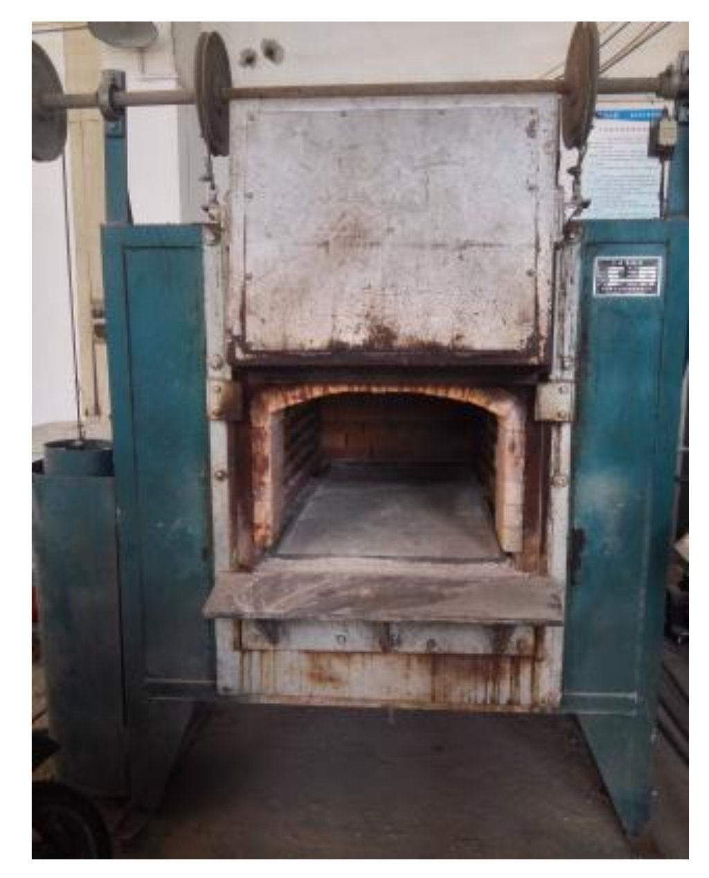
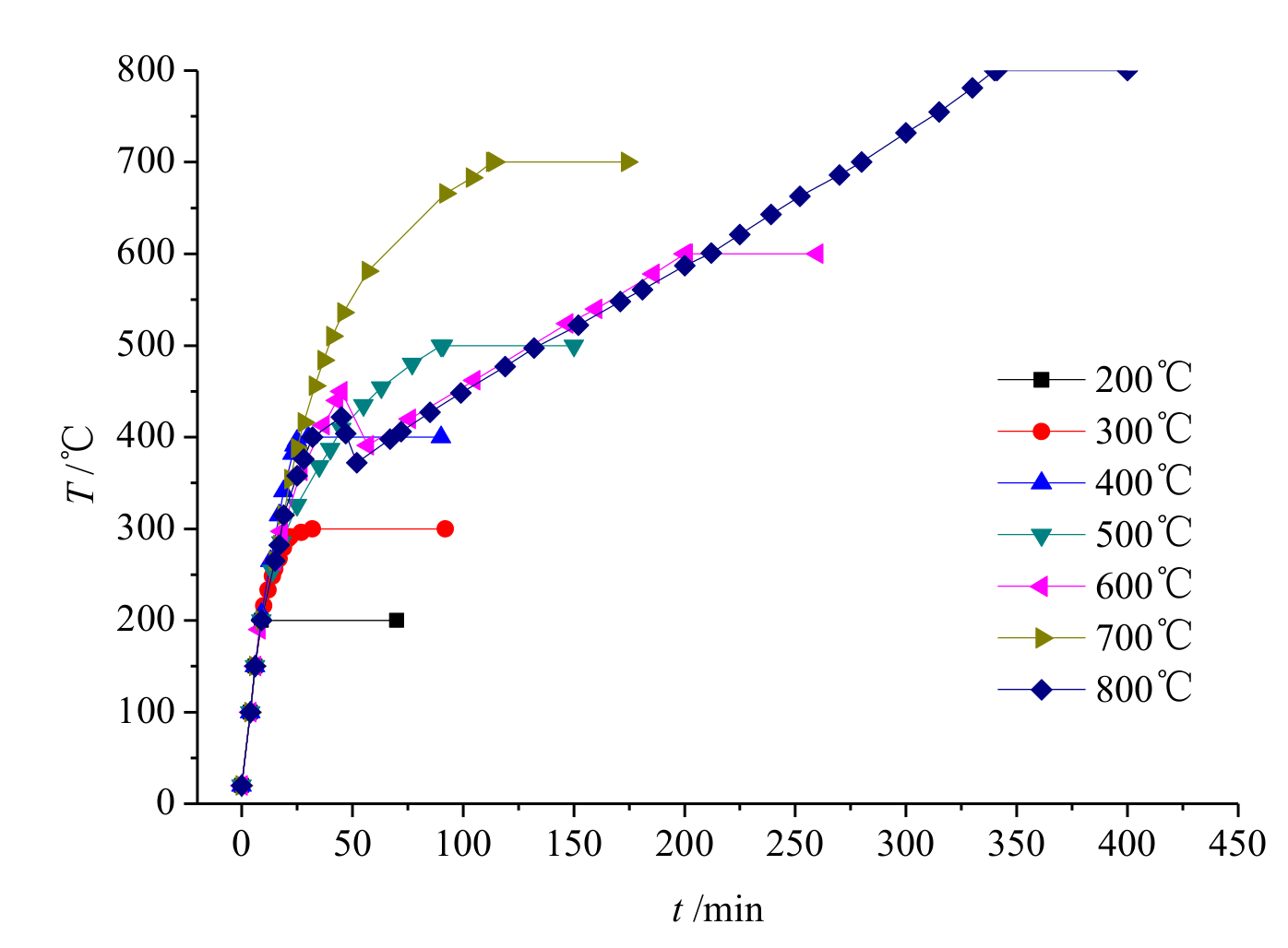
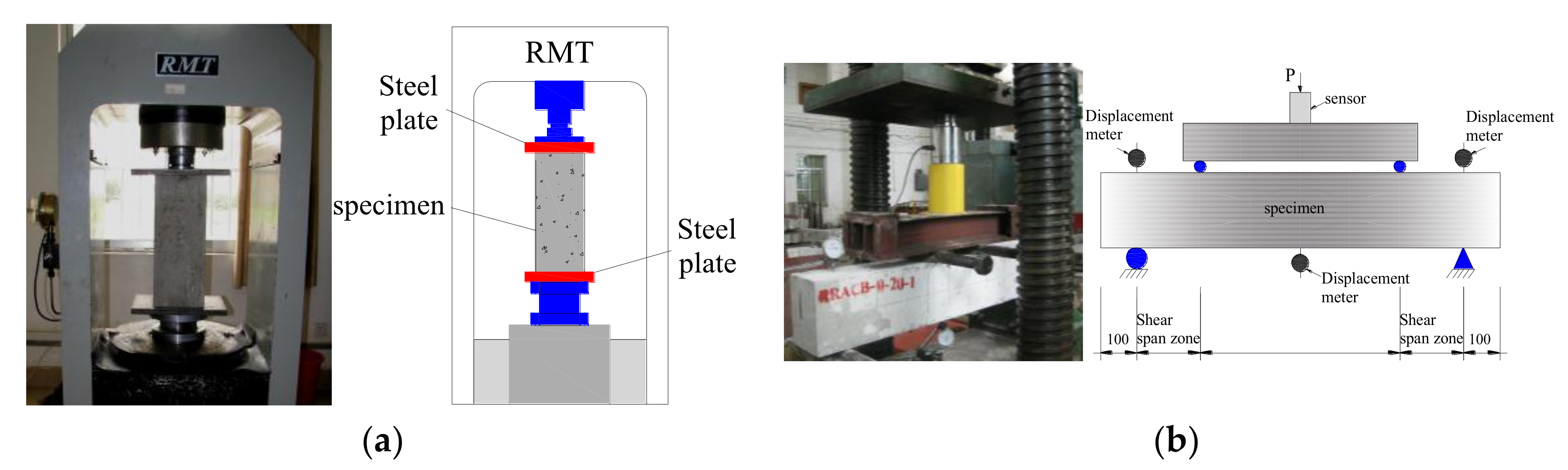
2.2. High-Temperature Installation and Loading System
3. Test Results
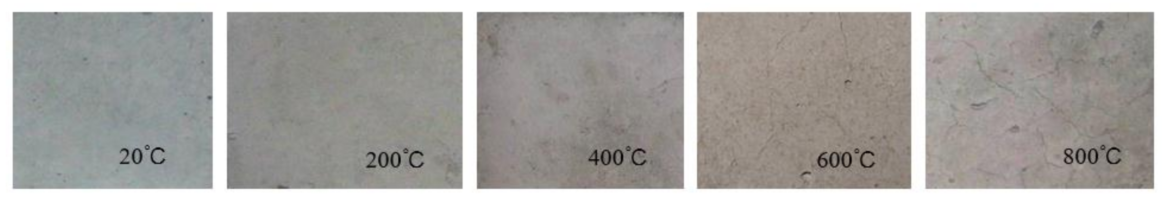
3.1. Surface Change
3.2. Mass Loss
3.3. Failure Mode
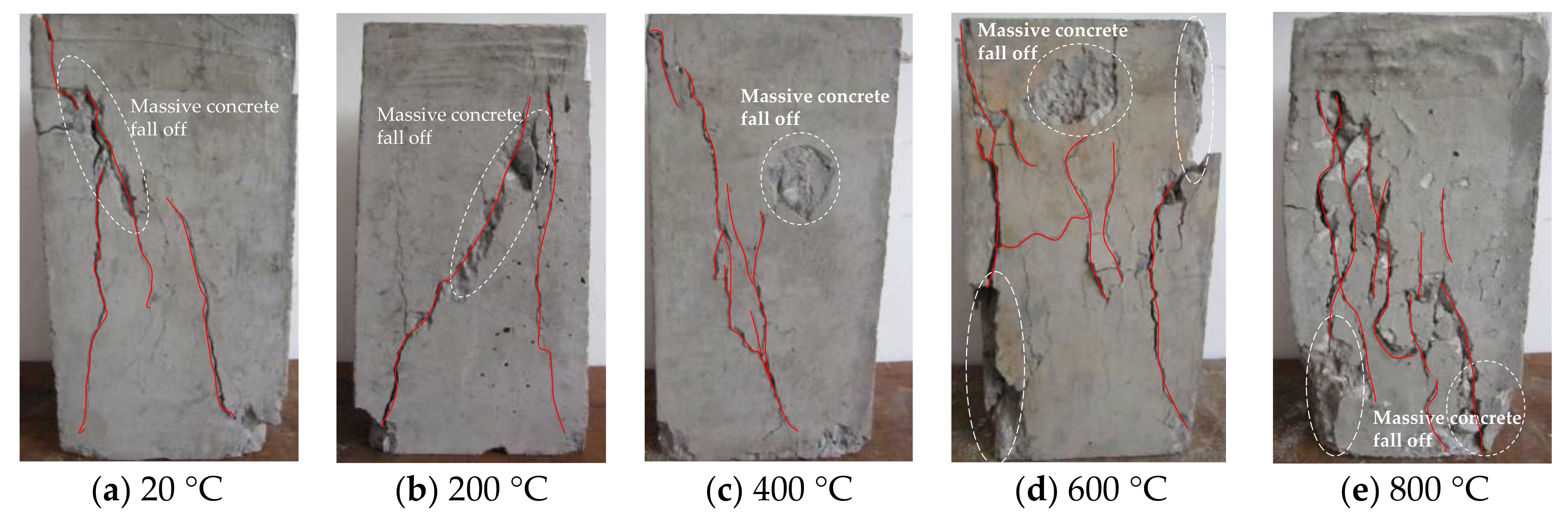
3.3.1. Failure Mode of Rectangular Prisms Specimens
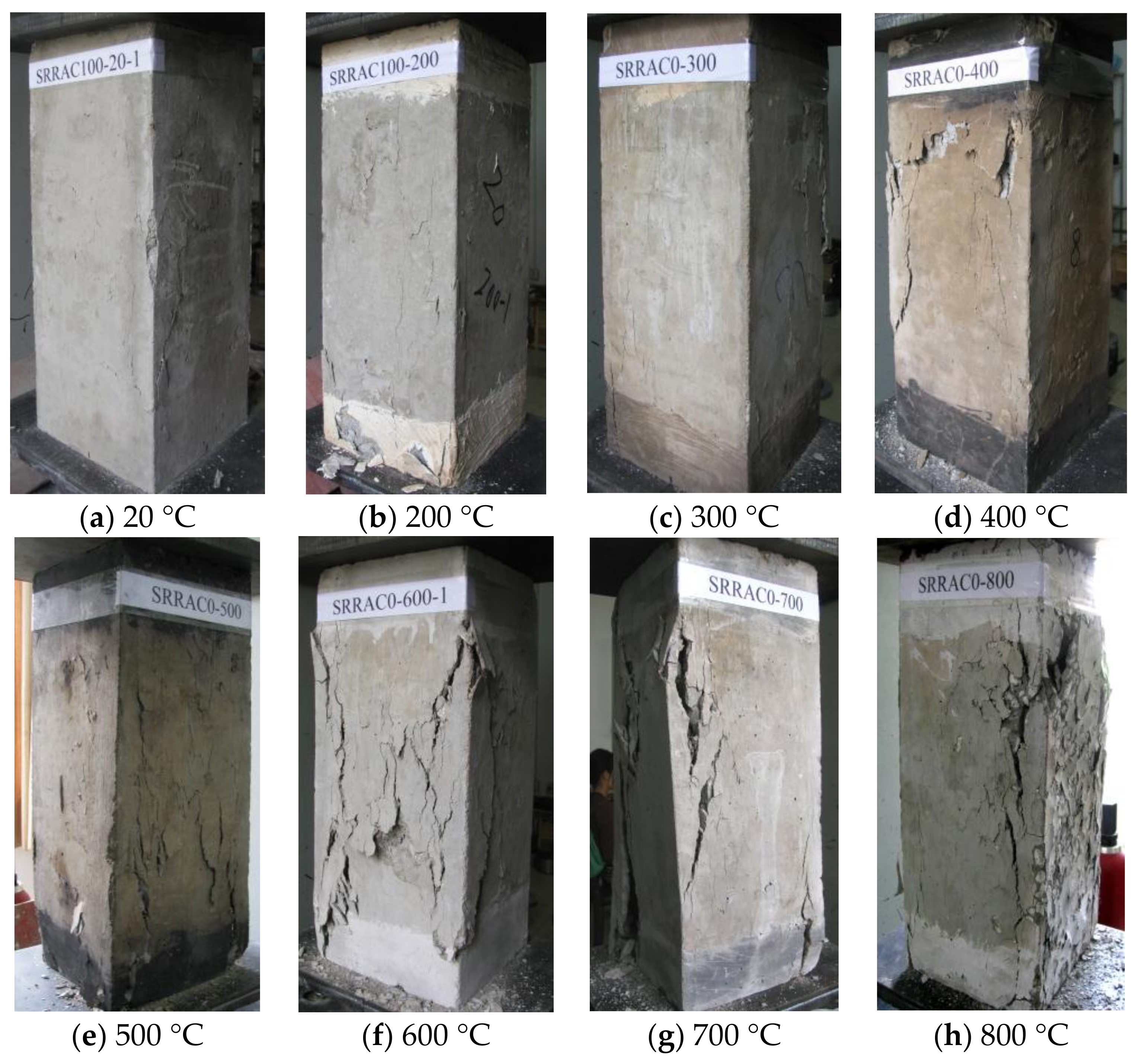
3.3.2. Failure Mode of SRRAC Columns
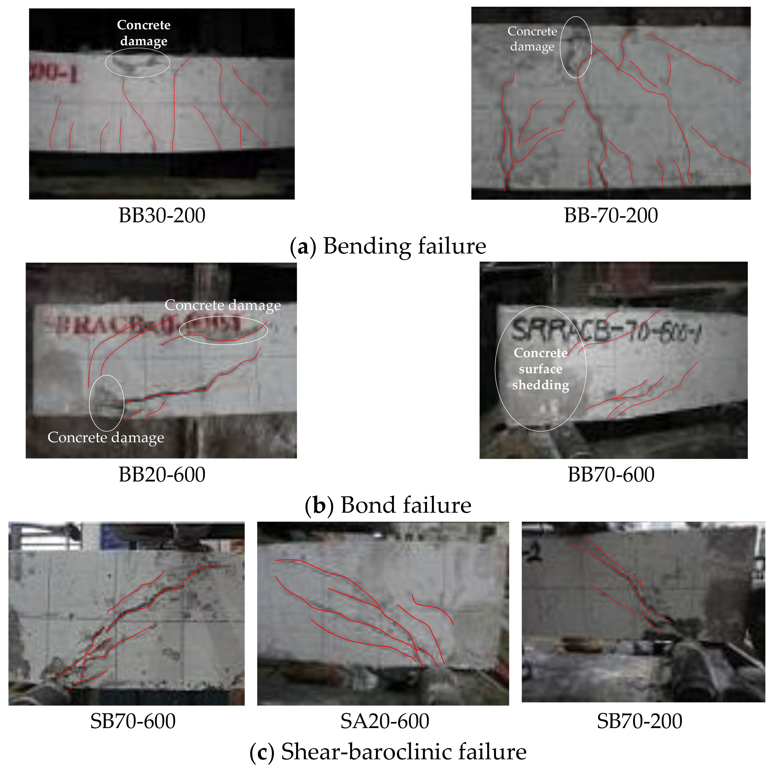
3.3.3. Failure Mode of SRRAC Beams
3.4. Load-Displacement Curve Analysis
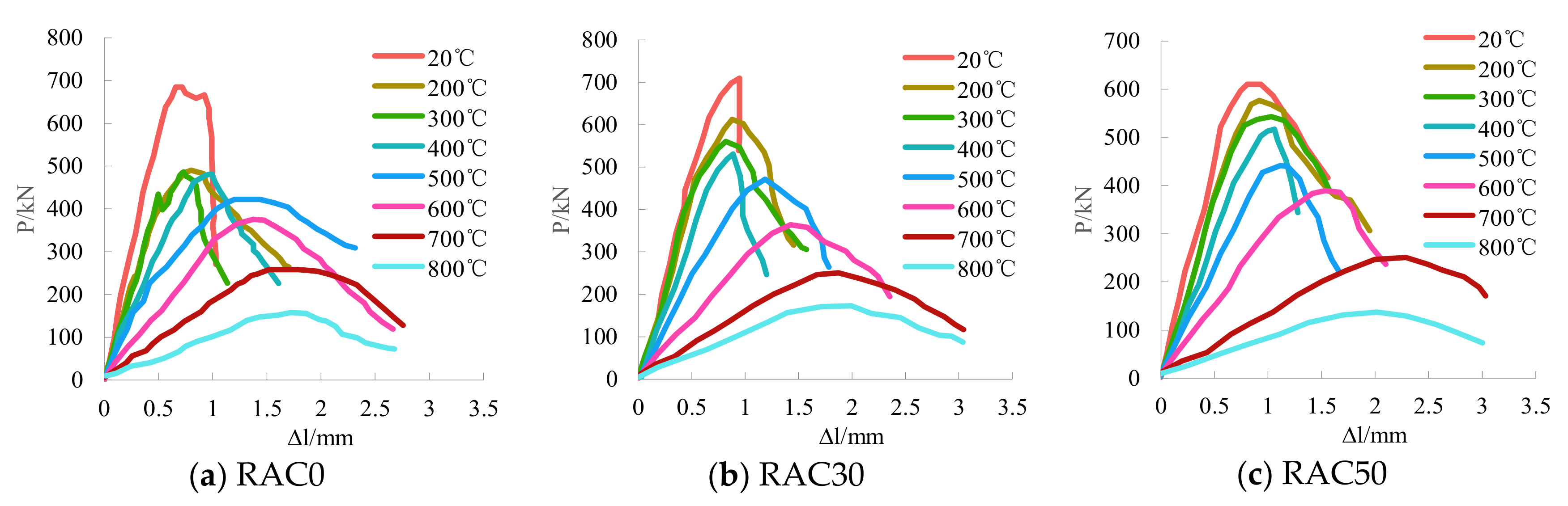
3.4.1. Load-Displacement Curve of Rectangular Prisms Specimens
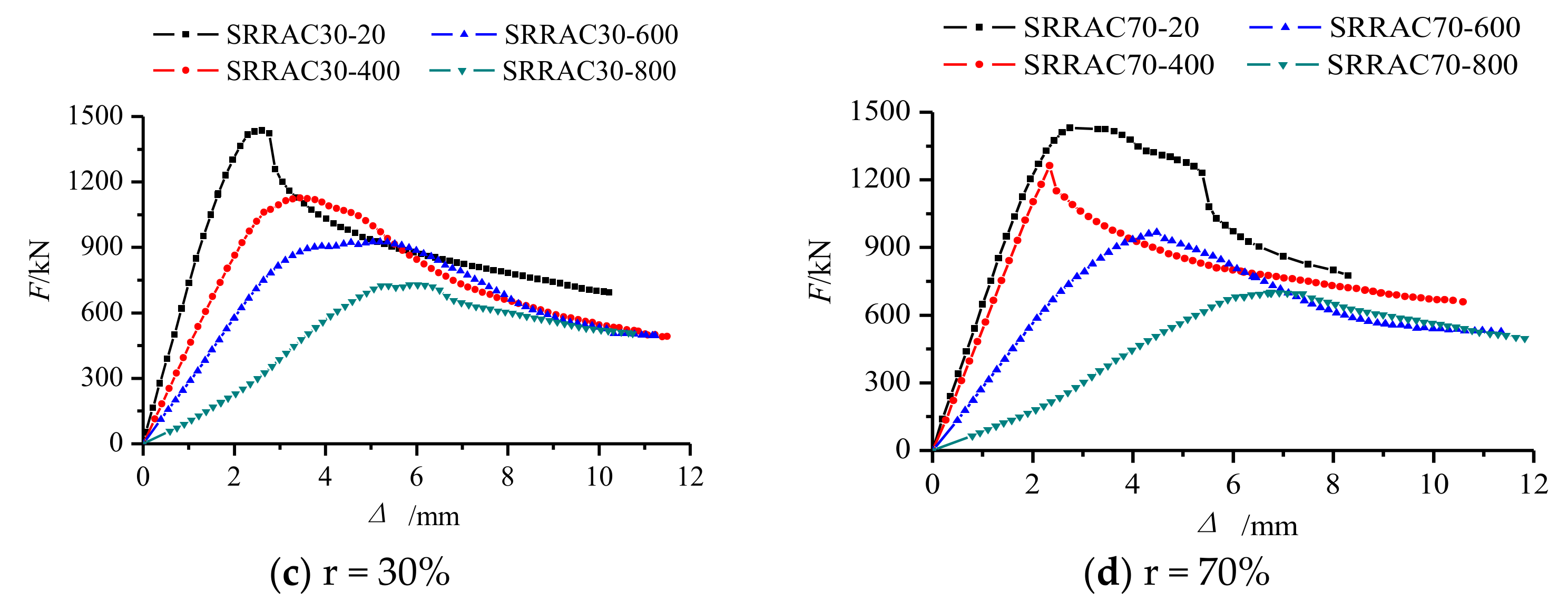
3.4.2. Load-Displacement Curve of SRRAC Columns
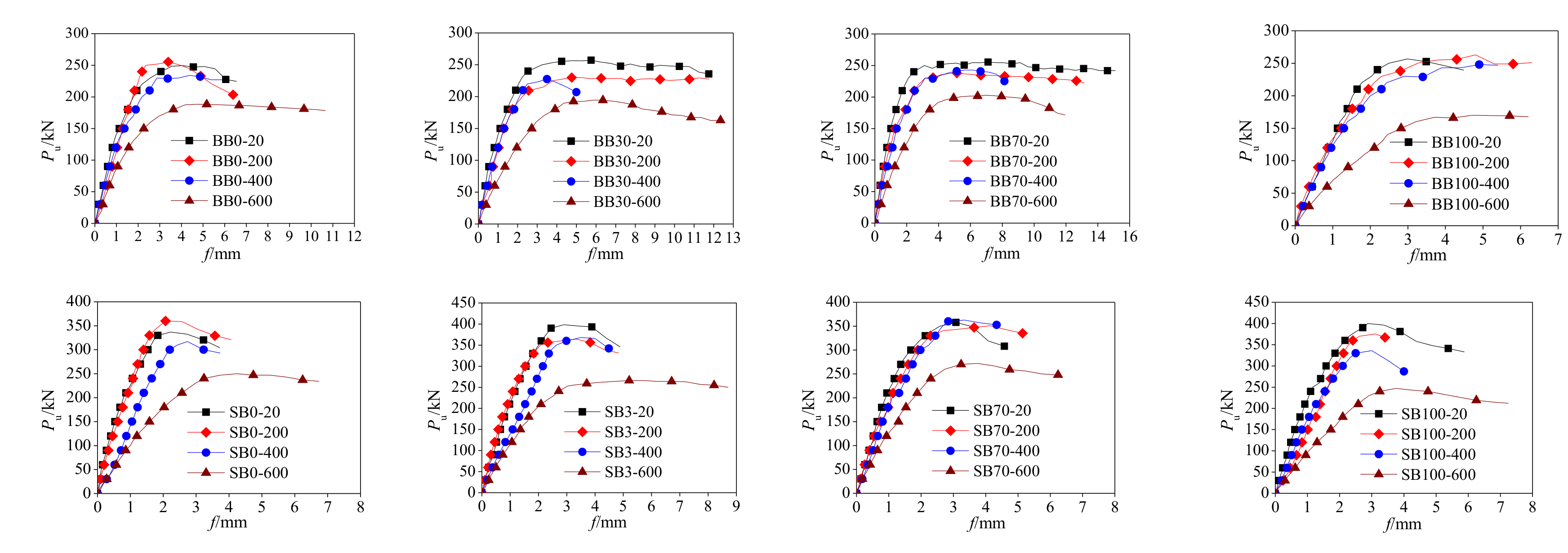
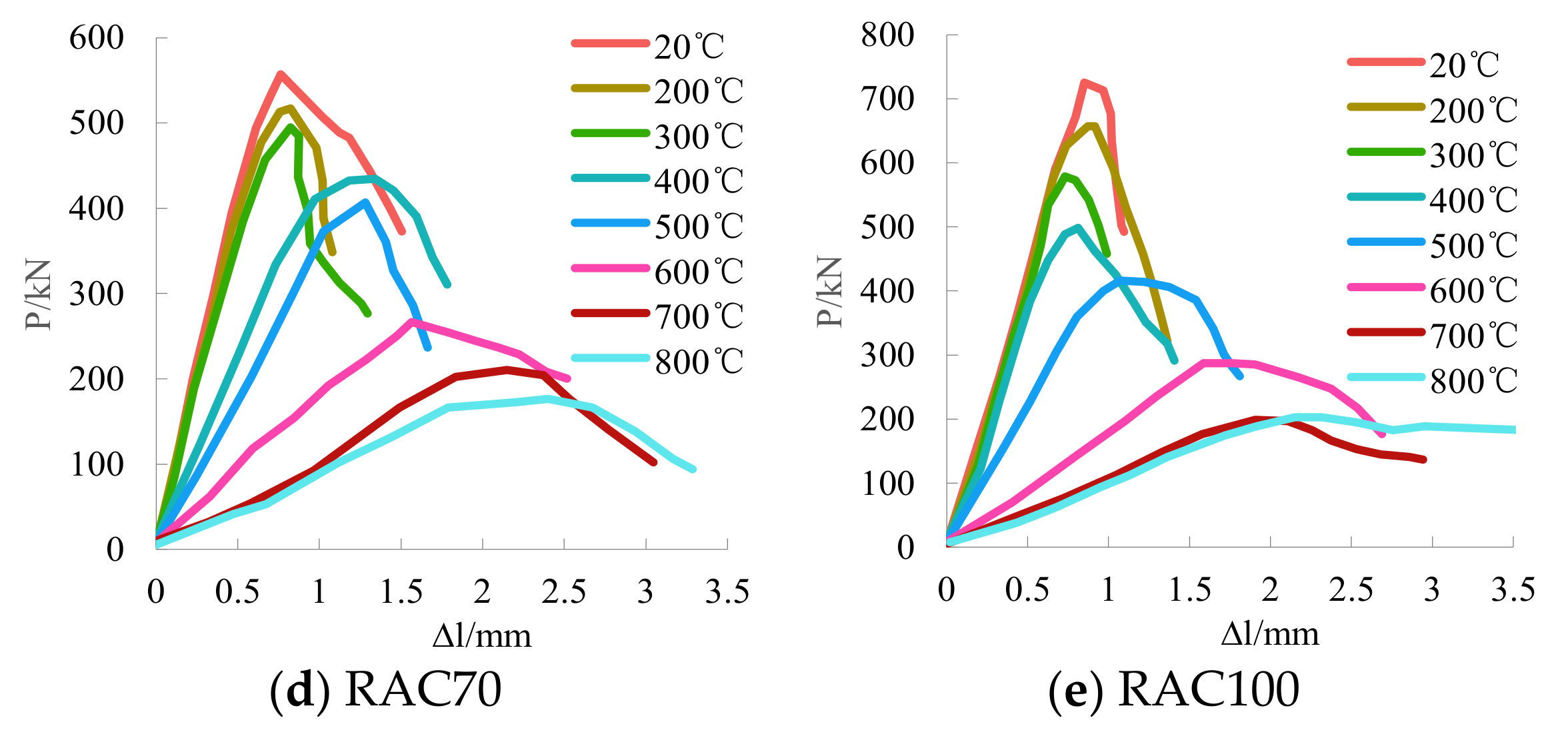
3.4.3. Load-Deflection Curve of SRRAC Beams
4. Residual Properties Analysis
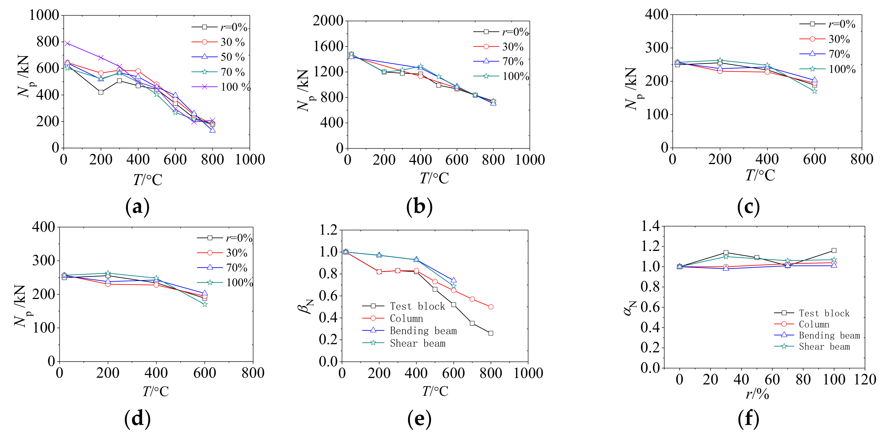
4.1. Bearing Capacity Degradation
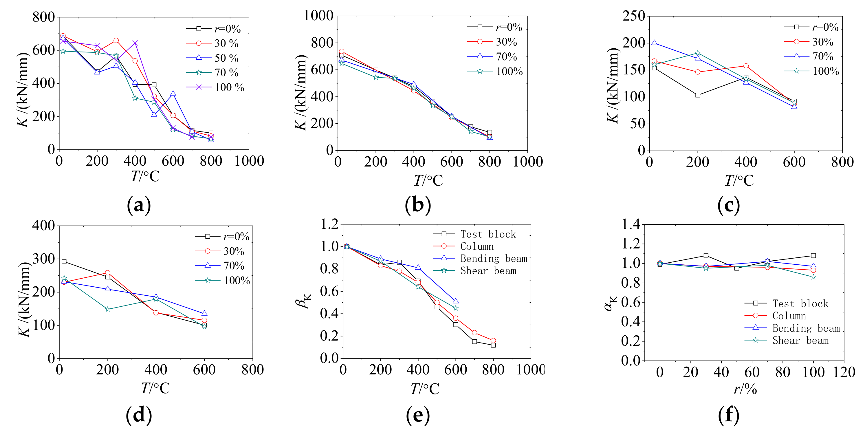
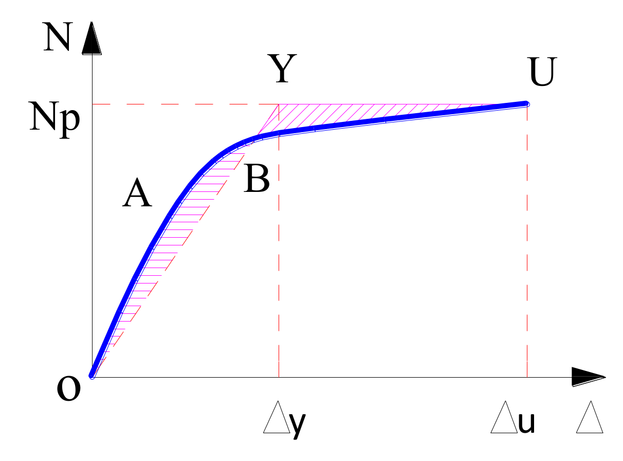
4.2. Stiffness Degradation
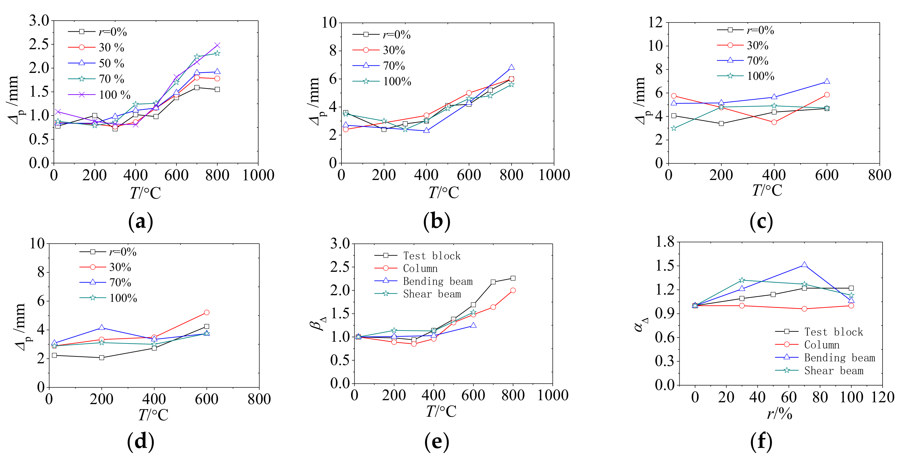
4.3. Peak Deformation
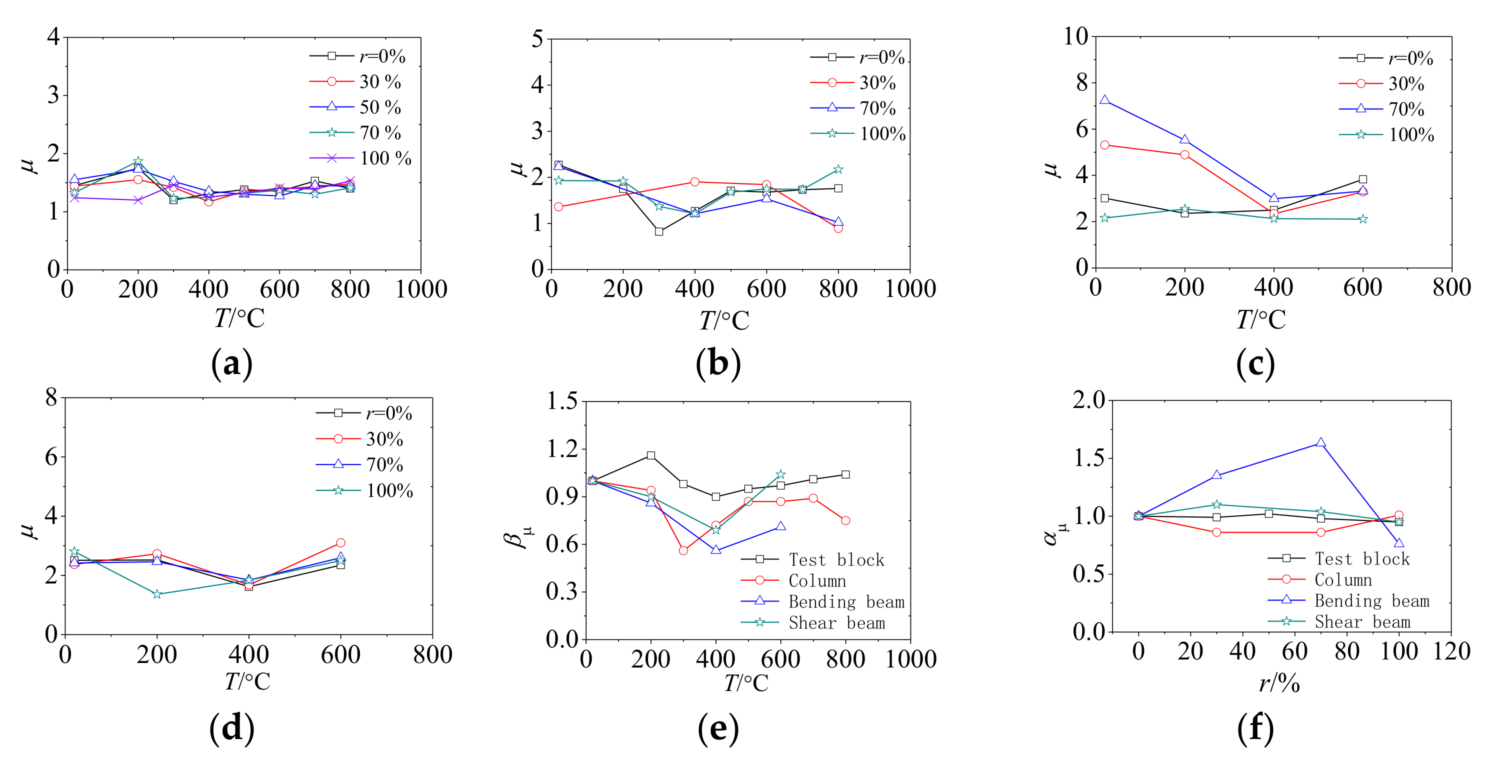
4.4. Ductility
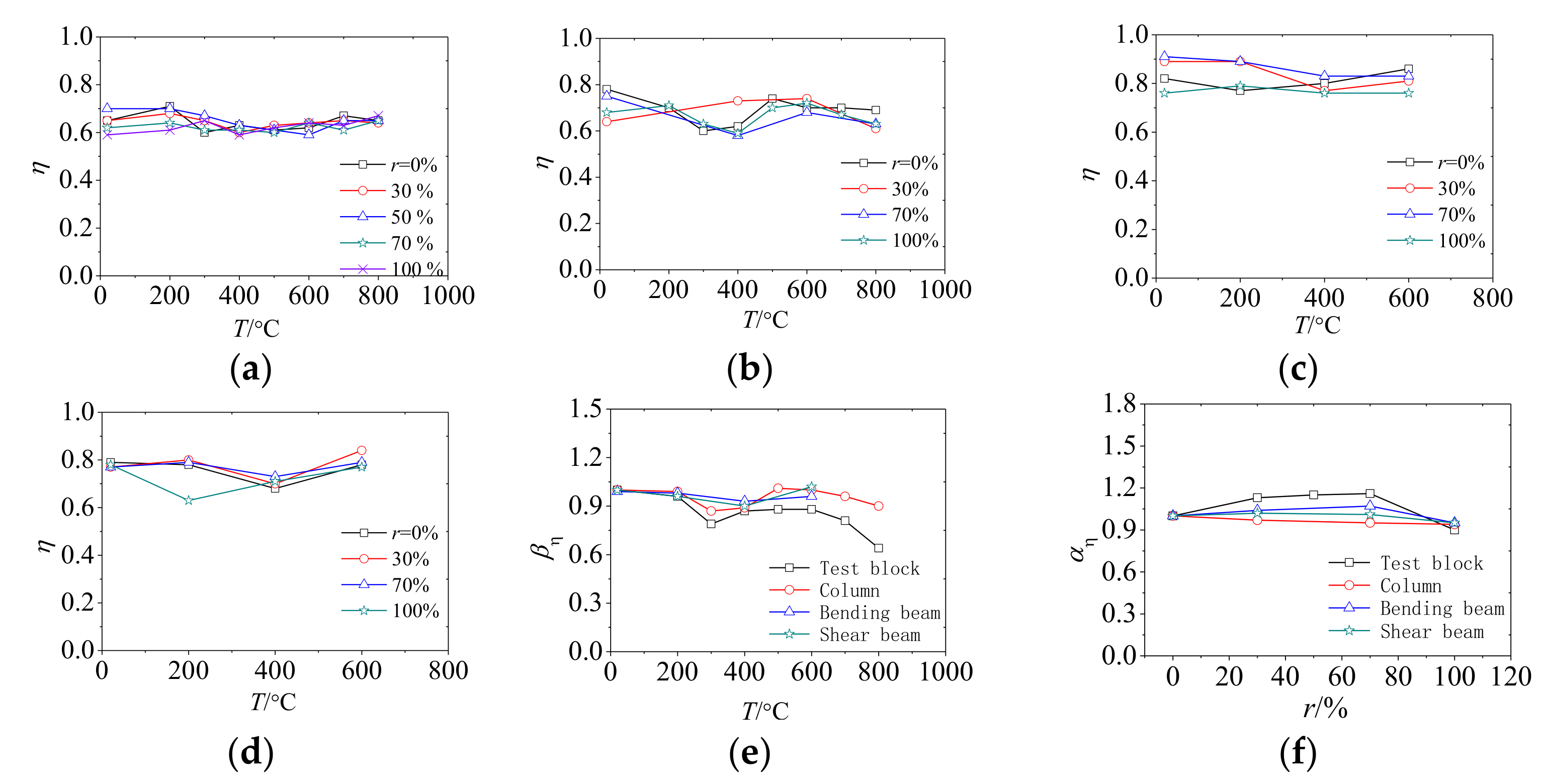
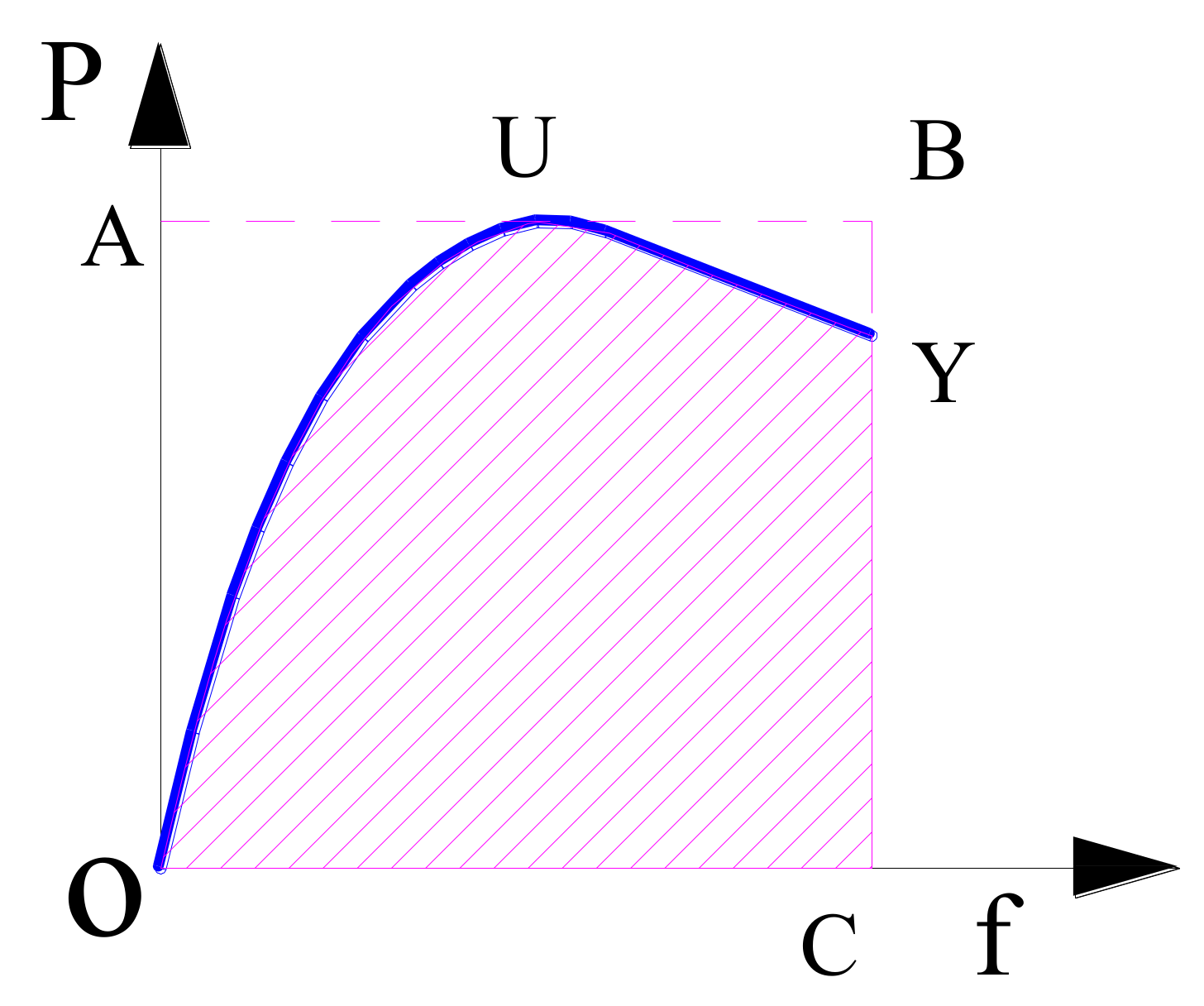
4.5. Energy Dissipation
5. Conclusions
- (1)
- Significant physical changes occurred on RAC surface after exposure to elevated temperature. Firstly, color on RAC surface changed from green-grey to gray-white. And then, chapped phenomenon occurs on the RAC surface when the temperature reached 600 degrees centigrade. Finally, the spalling phenomenon occurs on RAC surface when the temperature reaches 800 degrees centigrade. The phenomenon of mass loss can be found in the RAC after exposure to elevated temperature, and the phenomenon is more significant when the temperature and the replacement percentage increase.
- (2)
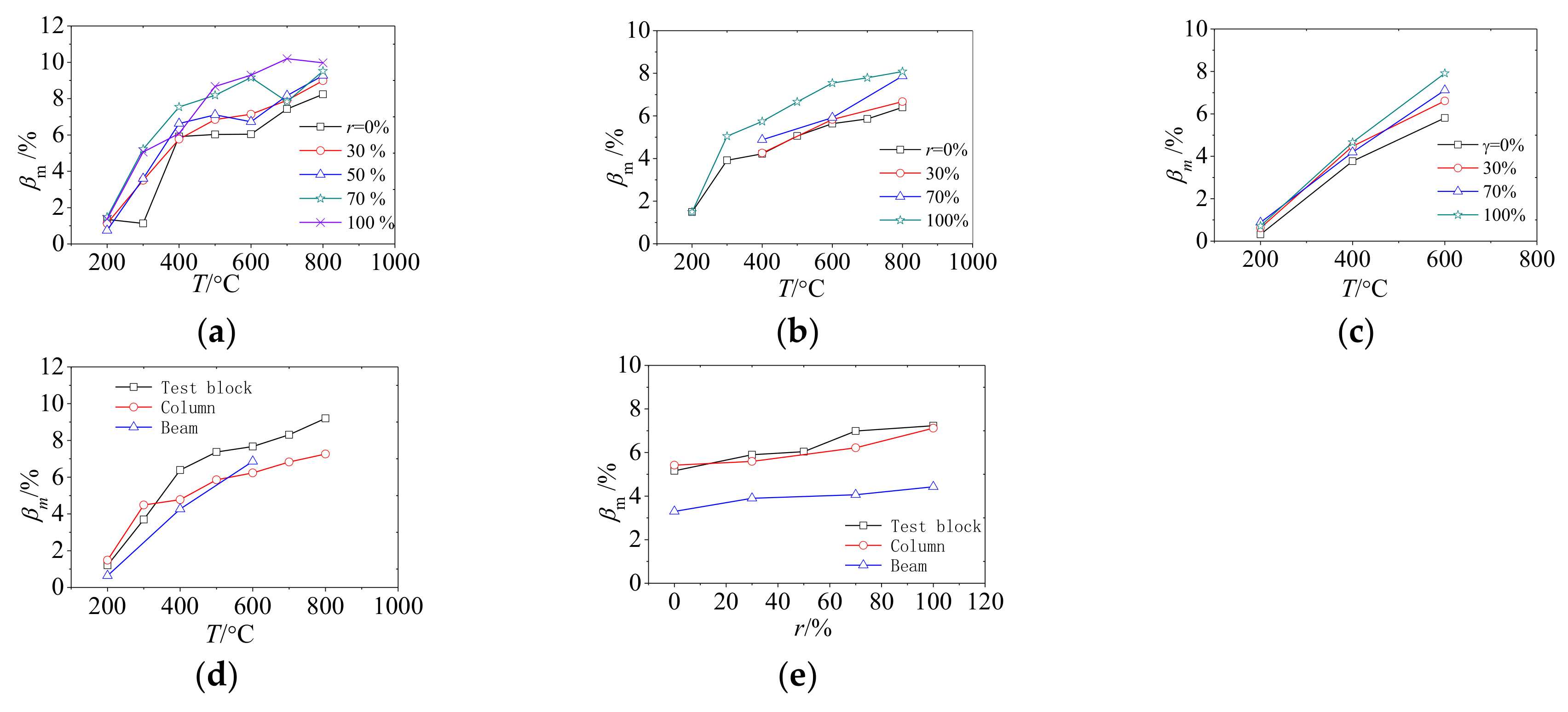
- Mechanical properties of RAC test blocks and SRRAC components are significantly degraded after exposure to elevated temperature. And its bearing capacity and stiffness degrade most obviously. And the performance of the prism test block degraded faster than SRRAC components. Performance degradation of SRRAC beams is slower than RAC test blocks and SRRAC columns.
- (3)
- The bearing capacity, stiffness and peak deformation vary slightly with temperature changes when the temperature is below 400 degrees centigrade. When the temperature exceeds 400 degrees centigrade, the bearing capacity and stiffness decrease steeply, and the peak deformation increases steeply. And ductility and energy dissipation are insignificant affected by elevated temperature.
- (4)
- Loss on ignition of specimen mass, the peak deformation and bearing capacity increase slightly with replacement percentage increases. The stiffness was significant fluctuation when replacement percentage was 70% to 100%. The ductility and energy dissipation were significant fluctuation when replacement percentage was 30% to 70%.
6. Future Research
- (1)
- This research focuses on the influence of the parameters (replacement percentage of recycled coarse aggregate and exposure to different temperatures) on the residual properties of SRRAC components. However, the coverage of steel bars or steel profiles can be influence on the mechanical properties of SRRAC components according to the regulations. Therefore, the influence of concrete cover and the coverage of steel bars or steel profiles on the residual properties of SRRAC components should be further discussed.
- (2)
- In this research, in order to ensure the same water–cement ratio of natural aggregate concrete and recycled aggregate concrete, the same amounts of water were used in the mix proportion. However, the porosity of recycled aggregate is higher than that of natural aggregate. So that the water absorption of recycled aggregate is higher than that of natural aggregate. Therefore, in order to get more accurate test results, it is necessary to further consider the influence of the water absorption of recycled coarse aggregate on effective water cement ratio.
- (3)
- In order to obtain more comprehensive laws of residual properties of SRRAC components after exposure to elevated temperature, the X-ray diffraction (XRD), thermogravimetric analysis (TGA) and SEM tests should be carried out for further research. Because XRD and TGA tests can reveal the chemical changes produced by the high temperatures in the concrete. And SEM tests and image analysis can identify on a microscopic scale the original, difference and failure procedures presented by the different samples.
Author Contributions
Funding
Acknowledgments
Conflicts of Interest
References
- Chen, Z.; Zhang, Y.; Chen, J.; Fan, J. Sensitivity Factors Analysis on the Compressive Strength and Flexural Strength of Recycled Aggregate Infill Wall Materials. Appl. Sci. 2018, 8, 1090. [Google Scholar] [CrossRef]
- Oikonomou, N. Recycled concrete aggregates. Cem. Concr. Compos. 2005, 27, 315–318. [Google Scholar] [CrossRef]
- Dhir, R.K.; Henderson, N.A.; Limbachiya, M.C. Sustainable Construction: Use of recycled concrete aggregate. Adv. Struct. Eng. 1998, 11, 383–396. [Google Scholar]
- Gómez-Soberón, J.M.V. Porosity of recycled concrete with substitution of recycled concrete aggregate: An experimental study. Cem. Concr. Res. 2002, 32, 1301–1311. [Google Scholar] [CrossRef]
- Loo, Y.H.; Tam, C.T.; Ravindrarajah, R.S. Recycled concrete as fine and coarse aggregate in concrete. Mag. Concr. Res. 1987, 39, 214–220. [Google Scholar]
- Abbas, A.; Fathifazl, G.; Fournier, B.; Isgor, O.B.; Zavadil, R.; Razaqpur, A.G.; Foo, S. Quantification of the residual mortar content in recycled concrete aggregates by image analysis. Mater. Charact. 2009, 60, 716–728. [Google Scholar] [CrossRef]
- Tam, V.W.; Wang, K.; Tam, C.M. Assessing relationships among properties of demolished concrete, recycled aggregate and recycled aggregate concrete using regression analysis. J. Hazard. Mater. 2008, 152, 703–714. [Google Scholar] [CrossRef] [PubMed]
- Kou, S.C.; Poon, C.S. Properties of concrete prepared with PVA-impregnated recycled concrete aggregates. Cem. Concr. Compos. 2010, 32, 649–654. [Google Scholar] [CrossRef]
- Hansen, T.C. Recycled concrete aggregate and fly ash produce concrete without portland cement. Cem. Concr. Res. 1990, 20, 355–356. [Google Scholar] [CrossRef]
- Evangelista, L.; Brito, J. Mechanical behaviour of concrete made with fine recycled concrete aggregates. Cem. Concr. Compos. 2007, 29, 397–401. [Google Scholar] [CrossRef]
- Choi, W.C.; Yun, H.D. Compressive behavior of reinforced concrete columns with recycled aggregate under uniaxial loading. Eng. Struct. 2012, 41, 285–293. [Google Scholar] [CrossRef]
- Butler, L.; West, J.S.; Tighe, S.L. The effect of recycled concrete aggregate properties on the bond strength between RCA concrete and steel reinforcement. Cem. Concr. Res. 2011, 41, 1037–1049. [Google Scholar] [CrossRef]
- Xiao, J.; Sun, Y.; Falkner, H. Seismic performance of frame structures with recycled aggregate concrete. Eng. Struct. 2006, 28, 1–8. [Google Scholar] [CrossRef]
- Reis, N.; Brito, J.D.; Correia, J.R.; Arruda, M.R.T. Punching behaviour of concrete slabs incorporating coarse recycled concrete aggregates. Eng. Struct. 2015, 100, 238–248. [Google Scholar] [CrossRef]
- Knaack, A.M.; Kurama, Y.C. Behavior of Reinforced Concrete Beams with Recycled Concrete Coarse Aggregates. J. Struct. Eng. 2015, 141, B4014009. [Google Scholar] [CrossRef]
- Ev, M.M.; Radonjanin, V.; Marinkovi, S.A. Recycled Concrete as Aggregate for Structural Concrete Production. Sustainability 2010, 2, 1204–1225. [Google Scholar]
- Fathifazl, G.; Razaqpur, A.G.; Isgor, O.B.; Abbas, A.; Fournier, B.; Foo, S. Shear capacity evaluation of steel reinforced recycled concrete (RRC) beams. Eng. Struct. 2011, 33, 1025–1033. [Google Scholar] [CrossRef]
- Jia, Y.D.; Guo, Y.K.; Sun, Z.P.; Zhao, X. Experimental Research on Behavior of Composite Beams of Steel-Reinforced Recycled Concrete. Adv. Mater. Res. 2013, 639–640, 145–148. [Google Scholar] [CrossRef]
- Fathifazl, G.; Razaqpur, A.G.; Isgor, O.B.; Abbas, A.; Fournier, B.; Foo, S. Flexural Performance of Steel-Reinforced Recycled Concrete Beams. ACI Struct. J. 2009, 106, 858–867. [Google Scholar]
- Fathifazl, G. Structural Performance of Steel Reinforced Recycled Concrete Components; Dissertation Abstracts International; Carleton University: Ottawa, ON, Canada, 2008; Volume 69, p. 1175. [Google Scholar]
- Xue, J.; Zhang, X.; Ren, R.; Zhai, L.; Ma, L. Experimental and numerical study on seismic performance of steel reinforced recycled concrete frame structure under low-cyclic reversed loading. Adv. Struct. Eng. 2018, 21, 1895–1910. [Google Scholar] [CrossRef]
- Ma, H.; Xue, J.; Liu, Y.; Zhang, X. Cyclic loading tests and shear strength of steel reinforced recycled concrete short columns. Eng. Struct. 2015, 92, 55–68. [Google Scholar] [CrossRef]
- Xue, J.; Zhai, L.; Bao, Y.; Ren, R.; Zhang, X. Seismic behavior of steel-reinforced recycled concrete inner-beam-column connection under low cyclic loads. Adv. Struct. Eng. 2017, 21, 631–642. [Google Scholar] [CrossRef]
- Ma, H.; Xue, J.; Zhang, X.; Luo, D. Seismic performance of steel-reinforced recycled concrete columns under low cyclic loads. Constr. Build. Mater. 2013, 48, 229–237. [Google Scholar] [CrossRef]
- Gonzalez, V.C.L.; Moriconi, G. The influence of recycled concrete aggregates on the behavior of beam–column joints under cyclic loading. Eng. Struct. 2014, 60, 148–154. [Google Scholar] [CrossRef]
- Govinda, G.G.; Rao, B.S.; Naik, S.M. Behaviour of Recycled Aggregate Concrete on exposed to Elevated Temperature. Int. J. Civ. Eng. 2017, 4, 5–13. [Google Scholar]
- Salau, M.A.; Oseafiana, O.J.; Oyegoke, T.O. Effects of Elevated Temperature on Concrete with Recycled Coarse Aggregates. In IOP Conference Series: Materials Science and Engineering; IOP Publishing: Bristol, UK, 2015; Volume 96, p. 012078. [Google Scholar]
- Laneyrie, C.; Beaucour, A.L.; Green, M.F.; Hebert, R.L.; Ledesert, B.; Noumowe, A. Influence of recycled coarse aggregates on normal and high performance concrete subjected to elevated temperatures. Constr. Build. Mater. 2016, 111, 368–378. [Google Scholar] [CrossRef]
- Gupta, A.; Mandal, S.; Ghosh, S. Recycled aggregate concrete exposed to elevated temperature. J. Eng. Appl. Sci. 2012, 7, 100–107. [Google Scholar]
- Liu, Y.; Ji, H.; Zhang, J.; Wang, W.; Chen, Y.F. Mechanical properties of thermal insulation concrete with recycled coarse aggregates after elevated temperature exposure. Mater. Test. 2016, 58, 669–677. [Google Scholar] [CrossRef]
- Chen, G.M.; He, Y.H.; Yang, H.; Chen, J.F.; Guo, Y.C. Compressive behavior of steel fiber reinforced recycled aggregate concrete after exposure to elevated temperatures. Constr. Build. Mater. 2016, 128, 272–286. [Google Scholar] [CrossRef]
- Guo, Y.C.; Zhang, J.H.; Chen, G.M.; Xie, Z.H. Compressive behaviour of concrete structures incorporating recycled concrete aggregates, rubber crumb and reinforced with steel fibre, subjected to elevated temperatures. J. Clean. Prod. 2014, 72, 193–203. [Google Scholar] [CrossRef]
- Li, W.; Luo, Z.; Wu, C.; Tam, V.W.Y.; Duan, W.H.; Shah, S.P. Experimental and numerical studies on impact behaviors of recycled aggregate concrete-filled steel tube after exposure to elevated temperature. Mater. Des. 2017, 136, 103–118. [Google Scholar] [CrossRef]
- Gu, L.; Ling, F.; Sheng, Z. Research on properties of concrete and its compositions after high temperature. Sichuan Build. Sci. 1991, 2, 1–5. (In Chinese) [Google Scholar]
- Zai, Q.; Hui, W. Research on Scanning Electron Microscopic of Concrete after High Temperature. J. Fuzhou Univ. 1996, S1, 36–40. (In Chinese) [Google Scholar]


| r/% | Cement/kg | Water/kg | Sand/kg | Natural Gravel/kg | Recycled Coarse Aggregate/kg |
|---|---|---|---|---|---|
| 0 | 500 | 215 | 532 | 1129 | 0 |
| 30 | 500 | 215 | 532 | 790.3 | 338.7 |
| 50 | 500 | 215 | 532 | 564.5 | 564.5 |
| 70 | 500 | 215 | 532 | 338.7 | 790.3 |
| 100 | 500 | 215 | 532 | 0 | 1129 |
© 2018 by the authors. Licensee MDPI, Basel, Switzerland. This article is an open access article distributed under the terms and conditions of the Creative Commons Attribution (CC BY) license (http://creativecommons.org/licenses/by/4.0/).
Share and Cite
Chen, Z.; Yao, R.; Jing, C.; Ning, F. Residual Properties Analysis of Steel Reinforced Recycled Aggregate Concrete Components after Exposure to Elevated Temperature. Appl. Sci. 2018, 8, 2377. https://doi.org/10.3390/app8122377
Chen Z, Yao R, Jing C, Ning F. Residual Properties Analysis of Steel Reinforced Recycled Aggregate Concrete Components after Exposure to Elevated Temperature. Applied Sciences. 2018; 8(12):2377. https://doi.org/10.3390/app8122377
Chicago/Turabian StyleChen, Zongping, Rusheng Yao, Chenggui Jing, and Fan Ning. 2018. "Residual Properties Analysis of Steel Reinforced Recycled Aggregate Concrete Components after Exposure to Elevated Temperature" Applied Sciences 8, no. 12: 2377. https://doi.org/10.3390/app8122377
APA StyleChen, Z., Yao, R., Jing, C., & Ning, F. (2018). Residual Properties Analysis of Steel Reinforced Recycled Aggregate Concrete Components after Exposure to Elevated Temperature. Applied Sciences, 8(12), 2377. https://doi.org/10.3390/app8122377