Article

Radiation from a Cavity-Backed Circular Aperture Array Antenna Enclosed by an FSS Radome

1
Hanwha Systems, Yongin 17121, Korea
2
Department of Electrical and Computer Engineering, Ajou University, Suwon 16499, Korea
3
Department of Electronic Engineering, Hanyang University, Seoul 04763, Korea
4
School of Electronic and Electrical Engineering, Hongik University, Seoul 04066, Korea
*
Author to whom correspondence should be addressed.
Equally contributed first authors.
Appl. Sci. 2018, 8(12), 2346; https://doi.org/10.3390/app8122346
Submission received: 29 October 2018 / Revised: 13 November 2018 / Accepted: 19 November 2018 / Published: 22 November 2018

Abstract

:
Radiation from a cavity-backed circular aperture array antenna enclosed by a frequency selective surface (FSS) radome is studied using the hybrid analysis method, by combining the mode matching method, the ray tracing technique, and Huygens’s principle. The equivalent magnetic surface currents on the apertures are derived from the aperture electromagnetic fields, which are calculated based on the mode matching method. The rays are generated from the equivalent magnetic surface currents and used to analyze the FSS radome based on the ray tracing technique. After being obtained from both the mode matching method and the ray tracing technique, electromagnetic fields on an outermost radome are transformed into the equivalent electric and magnetic surface currents using Huygens’s principle. The radiated fields are computed from the equivalent surface currents and compared with the measured data.

1. Introduction

A radome, a portmanteau of radar and dome, is a structural and weatherproof enclosure, and thus it is used to protect microwave antennas. The radome usually comprises dielectric layers that minimally affect electromagnetic signals to be transmitted or received by the antenna. Due to the effects of the radome on the electromagnetic signals, a thorough analysis of the radome is needed.
To understand electromagnetic properties of the radomes, there have been extensive studies on various radome configurations [1,2,3,4,5,6,7,8,9,10]. The radiation from a circular aperture surrounded by a hemisphere radome was predicted based on the dyadic Green’s function technique and physical optics (PO) method [2]. The Von Karman radome, one of the renowned radome structures, has been analyzed using the method of moments (MoM) [3], the coupled surface integral equation [4], and the aperture integration-surface integration (AI-SI) [5]. Furthermore, the radiation characteristic of hemisphere, tangent-ogive, and cone-shaped radomes with multiple sources has been investigated based on the multilevel fast multipole algorithm (MLFMA) [6]. The iterative physical optics-boundary integral-finite element method (IPO-BI-FEM) was used to analyze the sandwich tangent-ogive radome [7]. These studies focused on the radome consisting of dielectrics; however, the dielectric radome is generally responsible for the increase in radar cross section (RCS) of aircraft due to its broadband transmission characteristic. Instead, a frequency selective surface (FSS) radome, which is a curved FSS within a multi-layer radome, is employed to reduce RCS over a wide frequency range because it exhibits bandpass or bandstop characteristics. Previous studies have investigated electromagnetic characteristics of single- and multi-layer FSS radomes based on the pole residue matching (PRM) [8] and the ray tracing technique [9,10].
The FSS are one kind of the metasurfaces showing a bandpass or a bandstop characteristic. These characteristics are not found in natural materials. Metasurfaces, metamaterials, graphene, and plasmonics are gaining increasing popularity among researchers due to their ability to adjust permittivity or permeability purposely and manipulate electromagnetic waves passing through the materials. Due to numerous potential applications, a variety of studies have been conducted for sensing technology, plasmonics, graphene, and photonics [11,12,13,14,15,16]. There have also been studies on analyzing the properties of metamaterials and metasurfaces [17,18]. However, the investigation of electromagnetic properties for the complex structures which consist of a radome with the metasurfaces such as FSS and an aperture array antenna has not been presented. This is because it is hard to use the full-wave methods to analyze them, for a given memory usage and time, when an object is electrically large in size and complicated. Therefore, hybrid techniques combining the full-wave methods (such as MoM, FEM, finite-difference time-domain (FDTD), and the mode matching method) and the asymptotic methods (such as the ray tracing technique and geometric optics (GO)) are required, but related studies on radiation properties from array antennas enclosed by an FSS radome seem to be lacking. Therefore, it is of great significance to investigate electromagnetic properties of the aperture array antennas with the FSS radome using a hybrid technique combining the mode matching method for modeling aperture fields and the ray tracing technique for analyzing the radome.
In this paper, we analyze the radiation from a cavity-backed circular aperture array antenna enclosed by an FSS radome using the hybrid analysis method combining the mode matching method, the ray tracing technique, and Huygens’s principle. Towards this purpose, in particular, three different ways are carried out step by step. Firstly, electromagnetic characteristics of the cavity-backed circular aperture array antenna is predicted based on the mode matching method [19]. The obtained tangential electric fields are transformed into the equivalent magnetic current sources which in turn become rays to be used in the subsequent step. While using the rays, the ray tracing technique is employed to analyze the multi-layer FSS radome [10], and reflection and transmission properties of the FSS layer come from FEM simulations on HFSS. After obtained from the mode matching method and the ray tracing technique, electromagnetic fields on the outermost radome are transformed into the equivalent electric and magnetic surface currents using Huygens’s principle, and radiation fields in the far-field region are computed from the equivalent surface currents. In brief, we take an advantage of the hybrid analysis method combining the mode matching method, the ray tracing technique, and HFSS, a commercial EM simulator, based on FEM for an analysis of the aperture array antenna enclosed by the FSS radome. To verify our formulation, the FSS radome enclosing the cavity-backed circular aperture array antenna is fabricated and our computation results are compared with the measured data.

2. Field Analysis

Figure 1 shows the problem geometry. Assume that the z-oriented electric point source is located in a circular cavity with multiple circular apertures in a conducting plane. ϵ n and δ n are dielectric constant and loss tangent of each layer ( n = 1 , 2 , 3 , 4 , 5 ). Electromagnetic properties and size of each layer are shown in Table 1.
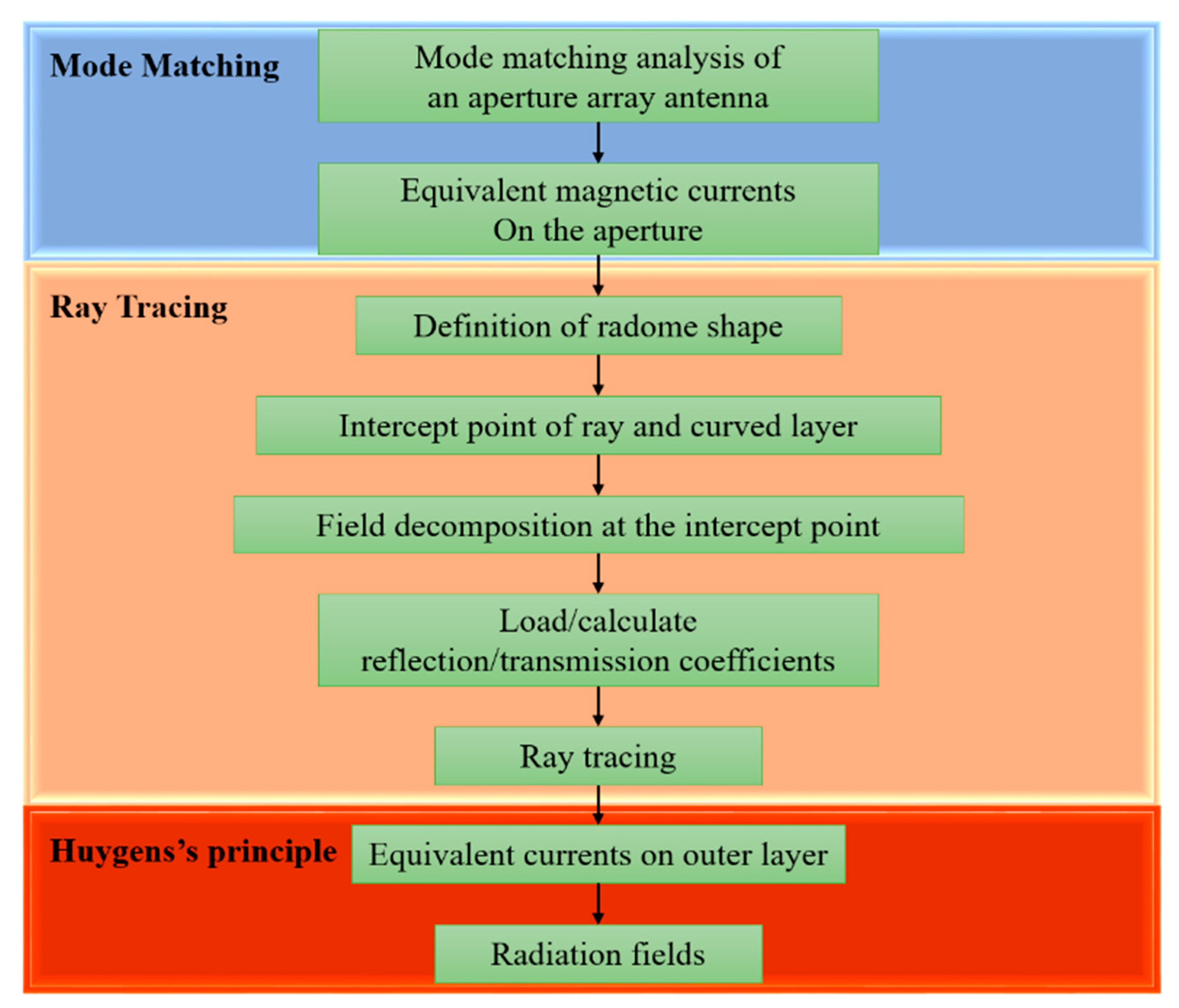
Figure 2 shows an entire analysis procedure for the radiation from a cavity-backed circular aperture array antenna with the FSS radome based on the hybrid analysis method combining the mode matching method, the ray tracing technique, and HFSS, a commercial EM simulator, based on FEM. Firstly, for analysis of the antenna, we solved the electromagnetic boundary-value problem of the circular cavity with the circular aperture array antenna based on the mode matching method in our previous study [19]. The mode matching method provides an advantage in the fact that its solution is rigorous and theoretically robust. Moreover, it is time-efficient in an analysis of open-boundary problems compared to other numerical techniques such as FEM, FDTD, and MoM, to name a few. An analysis using the mode matching method takes the following steps. Above all, the whole region to be solved is divided into sub-regions on a basis of boundary. Electromagnetic fields are defined in each region. Afterwards, boundary conditions are enforced to obtain a set of simultaneous equations for modal coefficients. Matrix calculation enables an evaluation of the modal coefficients and electromagnetic fields in all regions can be calculated based on the obtained modal coefficients. Note that the mode matching method should be used in the separable coordinate systems where eigen-modes can be defined in all regions. By using the tangential electromagnetic field established from the mode matching method and the surface equivalence theorem [20], we can derive the equivalent magnetic surface currents on the apertures from the aperture fields, which will be used in a formation of rays. Meanwhile, the FSS layer is a cross-loop dipole FSS which has a passband resonant frequency at 10 GHz. A detailed configuration and size of the designed FSS can be found in the reference [10]. Reflection and transmission coefficients of the designed FSS layer are obtained via numerous simulations using HFSS, an electromagnetic full-wave simulator. Reflection and transmission coefficients between dielectric layers, not involved with FSS layer, can be determined on a polarization basis, as described in the reference [10]. Afterwards, to apply the ray tracing technique for the analysis of the radiation from the cavity-backed circular aperture antenna enclosed by the FSS radome, we determined intercept points of the rays and the surfaces of the FSS radome using the iterative method [1]. Then, we can generate the rays from the equivalent magnetic surface currents on the apertures and trace the rays passing through the radome. When analyzing the multi-layer FSS radome, we used the ray tracing technique and the reflection and transmission coefficients at the FSS layer from the simulation of HFSS based on FEM [21]. Therefore, our hybrid method provides a more time-efficient method for analyzing the aperture array antenna enclosed by the multi-layer FSS radome than the method using the full-wave analysis only. On the other hand, it is noted that locally flat condition should be satisfied for the accuracy of the ray tracing technique. Since our radome structure has smooth surfaces, the ray tracing technique can be employed. Rough surfaces, ripples, and defects on the surface may decrease the accuracy. Additionally, the ray tracing technique is applicable to the region where the far-field condition is satisfied. In our analysis, each aperture is divided into hundreds of small cells to apply the ray tracing technique. Then, we calculated the radiation field from each small cell, respectively, and summed up all the computed fields based on the superposition principle. In this case, the far-field condition of each aperture is given by 2 D 2 / λ = 0.0267 m. Our ray tracing technique satisfies the far-field condition because the distance from the aperture center to the radome inner surface is larger than 0.142 m (4.75 λ ). Lastly, we calculated the electromagnetic fields and the equivalent electric and magnetic surface currents over the radome’s outer surface via using the results from the ray tracing technique. Then, the equivalent currents on the radome’s outer surface can be used to calculate the radiation fields in the far-field region.

3. Numerical Results and Measurement

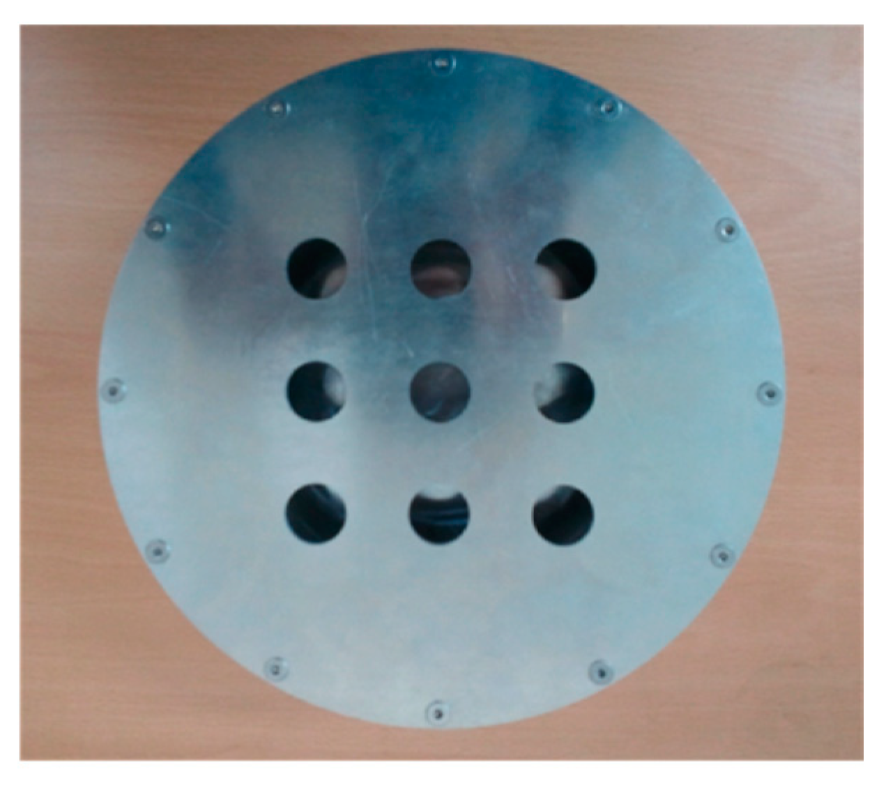
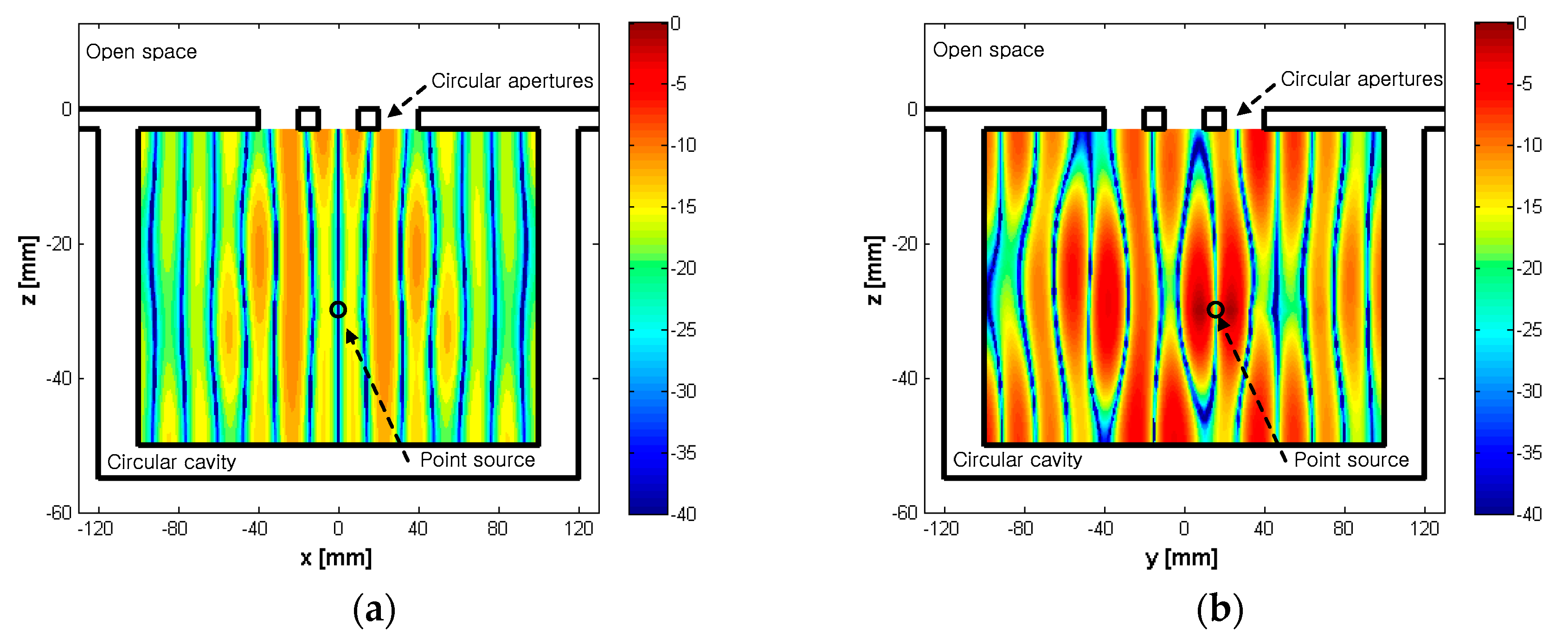
Before proceeding with the analysis of radiation pattern of the 3 × 3 circular aperture array antenna enclosed by the multi-layer FSS radome as shown in Figure 3, it is important to check the accuracy of our mode matching formulation and to analyze the antenna properties in detail. Firstly, the number of modes used is m = ± 19 ( ϕ direction) and n = 10 ( z direction). In order to ensure that the convergence was made, we tabulated the modal coefficients in the circular cavity in Table 2. From Table 2, we figured out that the contributing modes are TM ( - 4 ) 5 , TM 02 , TM 03 , TM 04 , TM 05 , TM 06 , TM 07 , TM 45 , and TE 02 . Also, we plotted normalized magnetic fields in the circular cavity at 10 GHz in Figure 4. It is seen that z -oriented electric point source affects the TM and TE modes simultaneously. Figure 5 depicts the magnitude of electric fields on each aperture. Note that the peak value occurs at the center of the middle aperture and the radiation becomes peak in a direction normal to the aperture array antenna. If the location of the electric point source in the cavity is changed, the electric fields on the apertures and radiation patterns are also changed. It means that the equivalent magnetic currents on the apertures can affect the radiation properties of the aperture array antenna enclosed by the multi-layer FSS radome and the electric and magnetic currents on the radome surface.
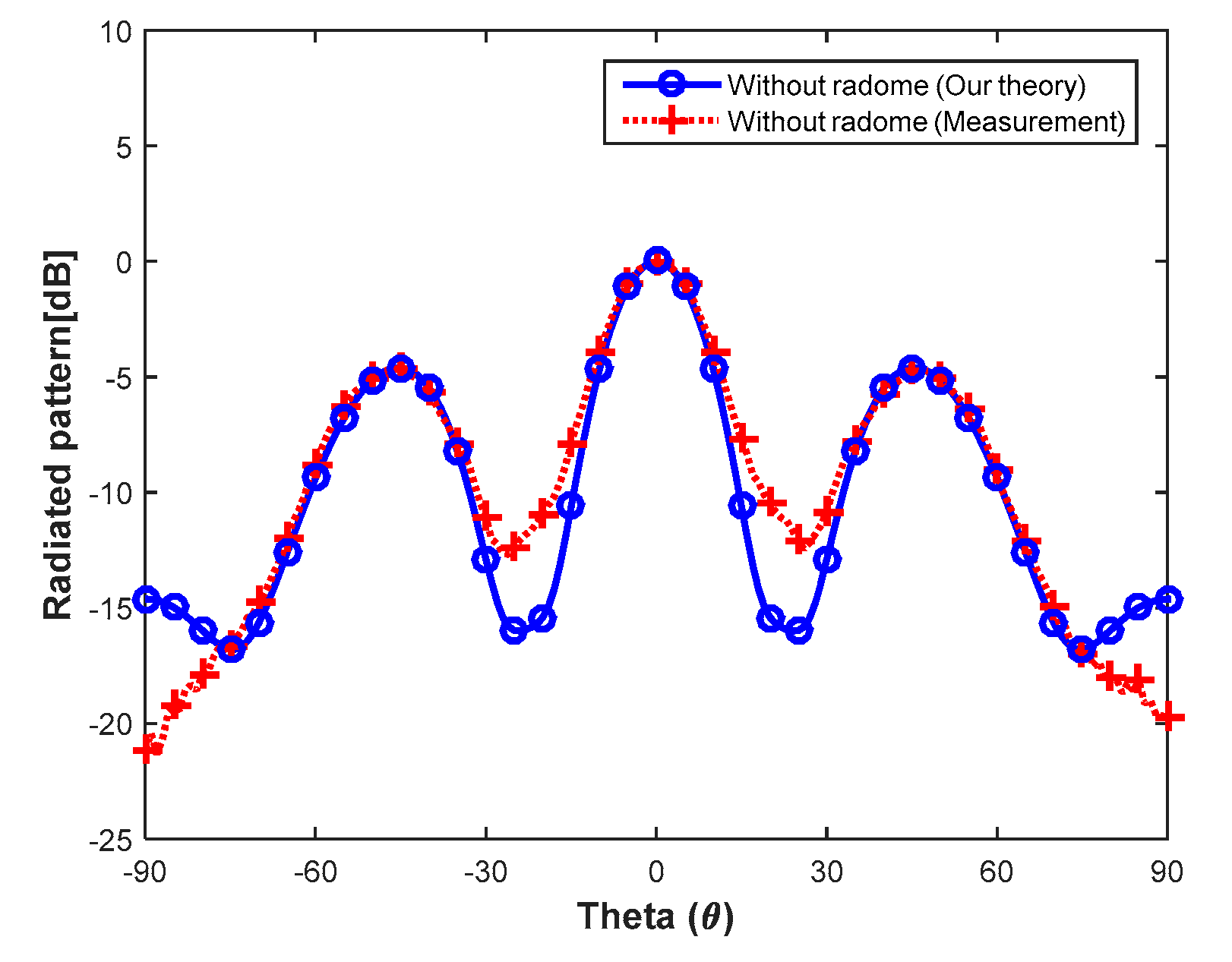
In order to further validate our formulation, we conducted the experiment. Figure 6 shows the normalized radiation pattern of the 3 × 3 cavity-backed circular aperture array antenna at 10 GHz. The comparison between our computation result (blue solid line with circle) and measured data (red dotted line with plus) generally shows a good agreement. Meanwhile, because of a difficulty in predicting reflection and transmission coefficients of a curved FSS layer, we exploited reflection and transmission coefficients under an assumption that the FSS layer is locally flat. The discrepancy between two results at higher degrees above about 75 comes from the fact that we assumed an infinite conductor plane when modeling the antenna.
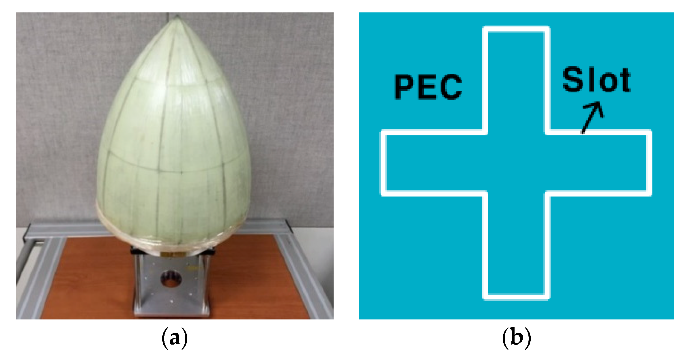
We fabricated a tangent-ogive multi-layer FSS radome (see Figure 7a) and the unit cell of the cross-loop dipole FSS layer (see Figure 7b and reference [10]). The multi-layer FSS radome is a foam-core sandwich type FSS. To be specific, the innermost and outermost layer are E-glass/epoxy and the third layer is the FSS layer. The remaining layers consist of a foam. The initially fabricated planar FSS layer is cut to shape and size, and then the cut pieces are molded through thermal-forming between the foam layers. The tangent-ogive multi-layer radome is one of the typical radomes. In this paper, we designed and fabricated the FSS radome to validate our hybrid method. When the cut pieces of the FSS sheet were molded on the radome, boundary lines between the pieces can cause an unavoidable defect of the FSS layer. In order to reduce effects of the defect, we chose a cross-loop dipole FSS because it is less vulnerable to the broken unit cell effect than others. In addition, the cross-loop dipole FSS has an excellent bandpass characteristic and is easy to fabricate while maintaining the unit cell of the FSS due to the rectangular configuration. This is why we chose the tangent-ogive multi-layer radome with the cross-loop dipole FSS. We also carefully fabricated the tip of the FSS radome to reduce the distortion of the transmitted wave. That is why we chose the tangent-ogive multi-layer radome with the cross-loop dipole FSS. We also carefully fabricated the tip of the FSS radome to reduce the distortion of the transmitted wave. Figure 8 illustrates measurement setup. We measured the radiation pattern of the cavity-backed circular aperture array antenna enclosed by the radome.
Figure 9 illustrates the radiation patterns of the 3 × 3 cavity-backed circular aperture array antenna with the designed FSS and dielectric radomes. These values are normalized to the maximum magnitude of the designed antenna without any radome. The dielectric radome is comprised of three layers; the innermost and outermost layer are E-glass/epoxy and the inserted layer between them is a foam. In other words, the second, third, and fourth layers are combined into one foam layer in Figure 1. As can be seen from Figure 9, the amount of the radiation field from the 3 × 3 cavity-backed circular aperture array antenna with the FSS radome is smaller than that with the dielectric radome. At θ = 0 ° , we found out that there is a discrepancy between our theoretical results and measured data. This is because the realistic FSS radome encompasses the curved FSS layer, but we consider this layer to be a planar structure in computation for convenience, which may lead to the difference. In addition, there may also be a fabrication error. Our analysis method can be used in the research of aperture antennas enclosed by the radome, terahertz sensors and any materials protected by the dome structure, and multi-physics problems [22,23,24,25,26].

4. Conclusions

The radiation from a cavity-backed circular aperture array antenna enclosed by a multi-layer FSS radome has been investigated using the hybrid technique combining the mode matching method, the ray tracing technique, and Huygens’s principle. The equivalent magnetic surface currents on the apertures are derived from the aperture fields, which are calculated based on the mode matching method. Then, rays are generated from the equivalent magnetic surface currents, which are used in an analysis of the multi-layer FSS radome by using the ray tracing technique. After obtained from both the mode matching method and the ray tracing technique, electromagnetic fields on an outermost radome are transformed into the equivalent electric and magnetic surface currents using Huygens’s principle. The radiated fields are computed from the equivalent electric and magnetic surface currents and compared with the measured data to validate our computation. We analyze the aperture array antenna enclosed by the FSS radome having a practical size and conduct the experiment for validation as a future work. Also, we plan to compare our results with other analytical models for more reliability of our method and to optimize our structure to improve the performance of the FSS radome through parametric studies.

Author Contributions

The present work was conducted in cooperation with all authors. J.K. and S.L. analyzed the problem and performed numerous simulations; J.K., S.L., H.S., K.-Y.J., H.C., and Y.B.P. contributed to the conceptualization, fabrication, and measurement; J.K. and S.L. wrote a draft which was edited by all co-authors.

Funding

This research received no external funding.

Acknowledgments

This work was supported by Basic Science Research Program through the National Research Foundation of Korea (NRF) funded by the Ministry of Science and ICT (No. 2017R1A2B4001903) and the Basic Science Research Program through the National Research Foundation of Korea (NRF) funded by the Ministry of Education (No. 2015R1A6A1A0303 1833).

Conflicts of Interest

The authors declare no conflict of interest.

References

  1. Kozakoff, D.J. Analysis of Radome-Enclosed Antennas, 2nd ed.; Artech House: Boston, MA, USA, 1997; pp. 103–183. ISBN 978-1-59693-441-2. [Google Scholar]
  2. Li, L.W.; Leong, M.S.; Ma, X.; Yeo, T.S. Analysis of a circular aperture antenna and its covered dielectric hemispherical radome shell over ground plane: Near- and far-zone patterns. Microw. Opt. Technol. Lett. 1999, 21, 238–243. [Google Scholar] [CrossRef]
  3. Arvas, E.; Rahhalarabi, A.; Pekel, U.; Gundogan, E. Electromagnetic transmission through a small radome of arbitrary shape. IEE Proc. H (Microw. Antennas Propag.) 1990, 137, 401–405. [Google Scholar] [CrossRef]
  4. He, M.; Xu, X.; Hu, B.; Zheng, Y. Accurate analysis of arbitrarily shaped wire antenna-dielectric radome structures. IEEE Antennas Wirel. Propag. Lett. 2007, 6, 408–410. [Google Scholar] [CrossRef]
  5. Meng, H.; Dou, W.; Yin, K. Analysis of antenna-radome system at millimeter wave band. In Proceedings of the 2008 Global Symposium on Millimeter Waves, Nanjing, China, 20–24 April 2008. [Google Scholar]
  6. Lu, C.-C. Dielectric radome analysis using multilevel fast multiple algorithm. In Proceedings of the IEEE Antennas and Propagation Society International Symposium, Boston, MA, USA, 8–13 July 2001. [Google Scholar]
  7. Meng, H.; Dou, W. Hybrid IPO-BI-FEM for the analysis of 2D large radome with complex structure. Microw. Opt. Technol. Lett. 2009, 51, 1348–1353. [Google Scholar] [CrossRef]
  8. Martini, E.; Caminita, F.; Nannetti, M.; Maci, S. Fast analysis of FSS radome for antenna RCS reduction. In Proceedings of the IEEE Antennas and Propagation Society International Symposium, Albuquerque, NM, USA, 9–14 July 2006. [Google Scholar]
  9. D’Elia, U.; Pelosi, G.; Pichot, C.; Selleri, S.; Zoppi, M. A physical optics approach to the analysis of large frequency selective radomes. Prog. Electromagn. Res. 2013, 138, 537–553. [Google Scholar] [CrossRef]
  10. Kim, J.H.; Chun, H.J.; Hong, I.P.; Kim, Y.J.; Park, Y.B. Analysis of FSS radomes based on physical optics method and ray tracing technique. IEEE Antennas Wirel. Propag. Lett. 2014, 13, 868–871. [Google Scholar]
  11. Zheludev, N.I.; Kivshar, Y.S. From metamaterials to metadevices. Nat. Mater. 2012, 11, 917–924. [Google Scholar] [CrossRef] [PubMed]
  12. Spada, L.L.; Vegni, L. Near-zero-index wires. Opt. Express 2017, 25, 23699–23708. [Google Scholar] [CrossRef] [PubMed]
  13. Yohan, L.; Sun-Je, K.; Hyeonsoo, P.; Byoungho, L. Metamaterials and metasurfaces for sensor applications. Sensors 2017, 17, 1726. [Google Scholar]
  14. Spada, L.L.; Vegni, L. Electromagnetic nanoparticles for sensing and medical diagnostic applications. Materials 2018, 11, 603. [Google Scholar] [CrossRef] [PubMed]
  15. Iovine, R.; Spada, L.L.; Vegni, L. Optical properties of modified nanorod particles for biomedical sensing. IEEE Trans. Magn. 2014, 50, 169–172. [Google Scholar] [CrossRef]
  16. Vakil, A.; Engheta, N. Transformation optics using graphene. Science 2011, 332, 1291–1294. [Google Scholar] [CrossRef] [PubMed]
  17. Padooru, Y.R.; Yakovlev, A.B.; Kaipa, C.S.; Hanson, G.W.; Medina, F.; Mesa, F.; Glisson, A.W. New absorbing boundary conditions and analytical model for multilayered mushroom-type metamaterials: Applications to wideband absorbers. IEEE Trans. Antennas Propag. 2012, 60, 5727–5742. [Google Scholar] [CrossRef]
  18. Monticone, F.; Alù, A. Metamaterials and plasmonics: From nanoparticles to nanoantenna arrays, metasurfaces, and metamaterials. Chin. Phys. B 2014, 23, 047809. [Google Scholar] [CrossRef]
  19. Kim, J.H.; Park, Y.B. Electromagnetic radiation from a circular cavity with circular apertures in a conducting plane. IEEE Trans. Antennas Propag. 2014, 62, 4846–4851. [Google Scholar] [CrossRef]
  20. Balanis, C.A. Advanced Engineering Electromagnetics, 2nd ed.; Wiley: New York, NY, USA, 2012; pp. 328–333. ISBN 978-0-470-58948-9. [Google Scholar]
  21. Philips, B.; Parker, E.A.; Langley, R.J. Ray tracing analysis of FSS radome for antenna RCS reduction. IEEE Proc. Microw. Antennas Propag. 1995, 143, 193–200. [Google Scholar] [CrossRef]
  22. Spada, L.L.; Iovine, R.; Tarparelli, R.; Vegni, L. Conical nanoparticles for blood disease detection. Adv. Nanopart. 2013, 2, 259–265. [Google Scholar] [CrossRef]
  23. Liu, Y.; Hao, Y.; Li, K.; Gong, S. Radar cross section reduction of a microstrip antenna based on polarization conversion metamaterial. IEEE Antennas Wirel. Propag. Lett. 2016, 15, 80–83. [Google Scholar] [CrossRef]
  24. Iovine, R.; Spada, L.L.; Vegni, L. Nanoplasmonic sensor for chemical measurements. Opt. Sens. 2013, 8774, 877411. [Google Scholar]
  25. Engheta, N. Circuits with light at nanoscales: Optical nanocircuits inspired by metamaterials. Science 2007, 317, 1698–1702. [Google Scholar] [CrossRef] [PubMed]
  26. Shaltout, A.M.; Kim, J.; Boltasseva, A.; Shalaev, V.M.; Kildishev, A.V. Ultrathin and multicolour optical cavities with embedded metasurfaces. Nat. Commun. 2018, 9, 2673. [Google Scholar] [CrossRef] [PubMed]
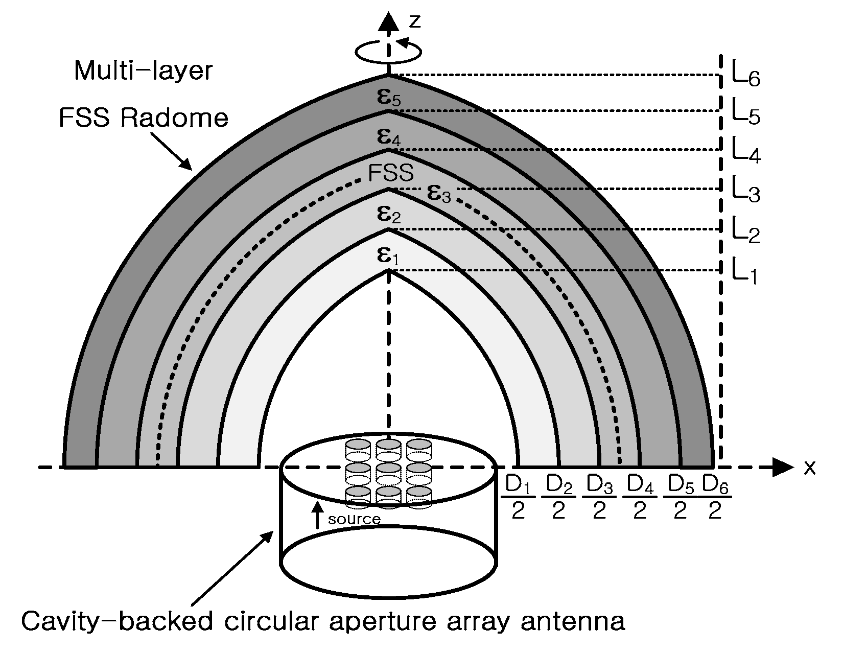
Figure 1. Problem geometry.
Applsci 08 02346 g001
Figure 2. Analysis procedure.
Applsci 08 02346 g002
Figure 3. The 3 × 3 cavity-backed circular aperture array antenna.
Applsci 08 02346 g003
Figure 4. Normalized internal (within the cavity) magnetic field in dB scale at 10 GHz. (a) H y ( x z -plane), (b) H x ( y z -plane).
Applsci 08 02346 g004
Figure 5. The magnitude of electric fields on each aperture.
Applsci 08 02346 g005
Figure 6. Radiation pattern of the 3 × 3 cavity-backed circular aperture array antenna ( φ = 0 ° ).
Applsci 08 02346 g006
Figure 7. (a) The FSS radome and (b) the unit cell of the FSS layer.
Applsci 08 02346 g007
Figure 8. Measurement setup.
Applsci 08 02346 g008
Figure 9. The dielectric and FSS radome enclosing the 3 × 3 cavity-backed circular aperture array antenna ( φ = 0 ° ).
Applsci 08 02346 g009
Table 1. Design parameters of the frequency selective surface (FSS) radome.
ParametersValueParametersValue
D1284.8 mmL1290.5 mm
D2286.4 mmL2291.5 mm
D3292.3 mmL3295.2 mm
D4292.4 mmL4295.3 mm
D5298.4 mmL5299.1 mm
D6300 mmL6300 mm
ϵr14.35δ10.0032
ϵr21δ20.0038
ϵr34.4δ30.02
ϵr41δ40.0038
ϵr54.35δ50.0032
Table 2. Convergence behaviors of the modal coefficients of the cavity.
| A mn | m = 19 m = 4 m = 0 m = 4 m = 19
n = 1 1.34 × 10⁻¹⁴ −3.89 × 10⁻¹ 1.40 × 10⁻¹ −3.59 × 10⁻¹ −1.36 × 10⁻¹⁴
n = 2 2.25 × 10⁻¹⁵ −2.89 × 10⁻² −2.05 −1.88 × 10⁻² −2.29 × 10⁻¹⁵
n = 3 5.57 × 10⁻¹⁶ 2.48 × 10⁻² 1.53 3.01 × 10⁻² −5.7 × 10⁻¹⁶
n = 4 1.18 × 10⁻¹⁶ 2.87 × 10⁻¹ 9.92 × 10⁻¹ 2.92 × 10⁻¹ −1.75 × 10⁻¹⁷
n = 5 1.64 × 10⁻¹⁷ −2.41 1.82 −2.44 −1.59 × 10⁻¹⁹
n = 6 −6.85 × 10⁻²⁰ 2.89 × 10⁻³ −1.82 2.92 × 10⁻³ 7.03 × 10⁻¹⁹
n = 7 −7.44 × 10⁻¹⁹ 6.69 × 10⁻⁶ −3.42 7.02 × 10⁻⁶ 1.99 × 10⁻¹⁹
n = 10 −7.33 × 10⁻²² −9.2 × 10⁻⁸ −2 × 10⁻⁵ −9.3 × 10⁻⁸ 6.36 × 10⁻²²
| B m n | m = 19 m = 4 m = 0 m = 4 m = 19
n = 1 2.06 × 10⁻¹⁵ −4.98 × 10⁻¹ −8.15 × 10⁻² −4.97 × 10⁻¹ −1.77 × 10⁻¹⁵
n = 2 3.56 × 10⁻¹⁶ −1.7 × 10⁻¹ −1.52 −1.66 × 10⁻¹ −2.91 × 10⁻¹⁶
n = 3 9.16 × 10⁻¹⁷ −1 × 10⁻¹ 6.52 × 10⁻¹ −9.1 × 10⁻² −7.06 × 10⁻¹⁷
n = 4 2.07 × 10⁻¹⁷ −4.31 × 10⁻² 3.33 × 10⁻¹ −5.44 × 10⁻² −1.44 × 10⁻¹⁷
n = 5 3.22 × 10⁻¹⁸ 3.1 × 10⁻¹ 3.27 × 10⁻¹ 3.31 × 10⁻¹ −1.64 × 10⁻¹⁸
n = 6 9.88 × 10⁻²⁰ −2.1 × 10⁻⁴ −4.46 × 10⁻² −2.1 × 10⁻⁴ 2.15 × 10⁻¹⁹
n = 7 −1.22 × 10⁻¹⁹ −7.1 × 10⁻⁶ −9.29 × 10⁻² −6.5 × 10⁻⁶ 1.68 × 10⁻¹⁹
n = 10 −3.42 × 10⁻²² −1.9 × 10⁻⁸ −8 × 10⁻⁶ −1.6 × 10⁻⁸ 3.07 × 10⁻²²